Scale-Master Posted November 15, 2013 Share Posted November 15, 2013 Beautiful workmanship! Quote Link to comment Share on other sites More sharing options...
Jeremy Jon Posted November 19, 2013 Author Share Posted November 19, 2013 Thank Gene & S-M! I haven't been able to upload photos, trouble with our internet/cable locally, being fixed, but frustrating, so will update with more once things running normal again! Quote Link to comment Share on other sites More sharing options...
Jeremy Jon Posted December 1, 2013 Author Share Posted December 1, 2013 Ya, I can post photos again!! More pics of WIP progress During cutting out of driver's door, upper window perimeter seal is reduced in thickness, to much to be reused & look proper New upper window perimeter seal is created, and fitted to contour Upper window perimeter seal fitted with smaller seal tab on inside edge, and formed tabs to each end, for realism of real production part once painted. Lower door seal created, and will be attached to final painted door, and also painted flat black Interior door frame built up to replicate production sheet metal, including forward door hinge pillar. New door sill kick-plate created, with photo-etch part created, Thank you Joseph! for realism of production stainless steel part which sits in the kick-plate Quote Link to comment Share on other sites More sharing options...
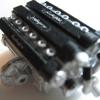
Jeremy Jon Posted December 1, 2013 Author Share Posted December 1, 2013 Stock kit components, upper firewall separate piece from main engine bay piece Beginning of modified engine bay pieces, master brake cylinder separated from upper firewall, all other molded in parts cut out (like battery, computer ECU, inner strut tower bulges, air conditioning dryer) Test fitment of engine and radiator pieces, and start of engine bay inner sheet metal being filled in Windshield shroud separated from body shell, and molded in wipers cut out Windshield shroud modified and test fitted in place, stock kit battery modified for further detail Test fitment of supercharger and intake system, revealed is major mistake by kit, it has NO throttle body molded in the plastic pieces?? WTH Quote Link to comment Share on other sites More sharing options...
Jeremy Jon Posted December 1, 2013 Author Share Posted December 1, 2013 Reference photo shows production throttle body (silver aluminum part) in position (near top of photo) New throttle body created, and built to be placed in proper position, between supercharger and air intake hose/box New fuse box created, with detailed lid and latch. New computer ECU created, with brackets and fasteners in place, ready for painting Quote Link to comment Share on other sites More sharing options...
Jeremy Jon Posted December 1, 2013 Author Share Posted December 1, 2013 Further scribe work on the body shell, to add realism after being painted, by keeping edges and panel lines crisp Visible edge of front fender, because door will be in open position, is thinned for realism Inner edge of each fender wheel well opening, is thinned by cutting inward at an angle, to create thinned edge Stock kit body shell missing gap between roof A-pillars and front fender, new joint gap created here for proper realism Quote Link to comment Share on other sites More sharing options...
Jeremy Jon Posted December 1, 2013 Author Share Posted December 1, 2013 Drill out the rear bumper side markers, so new clear plastic pieces can be created and installed later Stock kit body shell has deep molding scars at each of rear bumper corners, so must be filled to correct problem With drivers door opening completed, interior panels must be trimmed to correct shapes for realism. Dash board edge created with styrene, for correct look and shapes, for realism, as will be visible in opening upon completion Quote Link to comment Share on other sites More sharing options...
donb Posted December 1, 2013 Share Posted December 1, 2013 Serious workmanship Jeremy. Can't wait to see it complete. WOW! Quote Link to comment Share on other sites More sharing options...
Deathgoblin Posted December 1, 2013 Share Posted December 1, 2013 Excellent detail work. I'm watching this one. Quote Link to comment Share on other sites More sharing options...
Jeremy Jon Posted December 2, 2013 Author Share Posted December 2, 2013 Thanks Don & Brian! It's been a TON of work! Quote Link to comment Share on other sites More sharing options...
om617 Posted December 2, 2013 Share Posted December 2, 2013 Impressive work. Quote Link to comment Share on other sites More sharing options...
slusher Posted December 2, 2013 Share Posted December 2, 2013 Great attention to detail Jeremy. Excellent work.. Quote Link to comment Share on other sites More sharing options...
Terminator-Fox Posted December 3, 2013 Share Posted December 3, 2013 Awesome work Quote Link to comment Share on other sites More sharing options...
Jeremy Jon Posted December 4, 2013 Author Share Posted December 4, 2013 (edited) Thanks Tom, Carl & Steve More progress pics The stock kit wheels and tires are only fair in quality, but the tire most specifically incorrect size being to large overall diameter, and bald sidewall Originally donor tires from a C5 Corvette kit were considered, but though they had sidewall markings (Goodyear) they were to small in overall diameter Stock kit wheels are de-chromed in oven cleaner Stock kit wheels trimmed of ribs around outer drum surface, and sanded smooth, without distortion of front lip The stock kit wheels have noticeably rounded spokes, and center lug area closed in, so extra material removed to square shoulders of spokes and open center lug dish area To correct the tire issue, entirely new digitally designed tires developed (thank you Joseph), making a production correct Goodyear band tire, correct tread design, and correct dimensions (using the stock kit wheels dimensions I.D.) First 3D print of the digitally designed tires, showing good tread and sidewall markings Final print of the digitally designed tires ready for use, shown compared to stock kit wheel & tire set Painted of final version tire and modified wheels, ready for use For realism, tires painted with flat black in tread blocks and inner wall, and satin black on outer sidewalls (simulates detailed/cleaned tires) Edited December 4, 2013 by Jeremy Jon Quote Link to comment Share on other sites More sharing options...
slusher Posted December 4, 2013 Share Posted December 4, 2013 Wheels and tires look great. Quote Link to comment Share on other sites More sharing options...
Jeremy Jon Posted December 4, 2013 Author Share Posted December 4, 2013 Thanks Carl! If I had more time, or was a personal build, I think I might have had the wheels redone by digital design also, but for the time and resources constraints, the tires were the more immediate need Quote Link to comment Share on other sites More sharing options...
Jeremy Jon Posted December 6, 2013 Author Share Posted December 6, 2013 More progress pics! Door is going to stay in an open position for display purposes, but the inner door frame & hinges are scratch built using photo etch bars & hard wire rod, to look like the production car, once all is painted, then the door pins allow it to slide down directly into pivots Door hung in test fit, showing proper appearance, and articulation into the front fender Engine hood is modified with photo etch pivot bars also, bent and modified to sit flush, hard wire bent and placed inset of fender underside to connect and articulate hood, and pivot point(s) located as far back as possible, so hood opens up and clear of the cowl, while giving a much smaller volume than the plastic kit hinge arms Quote Link to comment Share on other sites More sharing options...
Jeremy Jon Posted December 6, 2013 Author Share Posted December 6, 2013 Underside of hood given some scratch built detailing around edges to simulate bracing, and under hood covering simulated using layers of tape, cut to shapes and until thickness enough for appearance, later will be painted in flat black, and glued to under side position of finished painted hood With all priming and wet sanding done, final coat of fine white primer is sprayed & wet sanded (to 2K grit), then first coat of acrylic lacquer applied After first lacquer coat, each piece wet sanded (starting from 1K grit and up), then washed thoroughly and let to dry Quote Link to comment Share on other sites More sharing options...
Jeremy Jon Posted December 6, 2013 Author Share Posted December 6, 2013 Back to the engine bay, stock plastic parts being modified or enhanced for realism, like the coolant hose assemblies, made of thicker gauge line, and formed to shape, cast splitter housing enhanced with sensors and further detail Test fit of upper coolant hose parts Basic engine being put together and modified for detail, styrene added to front of cylinder heads, so to fill in under valve covers properly, styrene strips scratch built and added over fuel injector ports, to simulate production car Stock plastic accessory belt parts modified, my method is to mark the face with ink, then scrape away the inside surfaces to thin the belt portions, cutting the inside corners alongside pulleys, leaving the backside of the belts slightly thicker for strength, but the face edge as thin possible for realistic appearance Upper coolant hose towers modified on engine block, adding second hose ports, for realism After the first accessory belt part modified, painted and installed, the secondary belt part is also modified, painted and installed, because the lower half of these parts will be fairly hidden down in between the engine & radiator shroud, there isn't as much modification required Quote Link to comment Share on other sites More sharing options...
Jeremy Jon Posted December 7, 2013 Author Share Posted December 7, 2013 More progress pics! Engine supercharger assembly and air box also modified and enhanced, sensors added, and ultra-thin copper wire used to create sensor wire leads, which once painted will integrate into chassis wire harness Engine wiring harness(s) constructed, using thin wires, twisted around each other to hold shape, and provide braches like individual fuel injector plug ends With all individual parts painted, using various semi-gloss and flat paints + clears, to give complexity of surface colourings, are all assembled Quote Link to comment Share on other sites More sharing options...
Jeremy Jon Posted December 7, 2013 Author Share Posted December 7, 2013 Comparison of some stock plastic kit parts, to finished modified and painted assembly Power steering fluid housing constructed, of clear plastic tube body, sanded for frosted white semi-transparent appearance, with fluid paint to be added after to hollowed interior for realism & semi-visible through frosted container Lid portion cut off & new part scratch built, using photo etch turn cap, and ultra-fine copper wire as cap leash, to be painted and attached to reservoir after attached to engine front Coolant reservoirs modified, opaque lid sections cut from bottom, and new bottom portions constructed of clear plastic & clear resin filler, until correct shape, and sanded for semi-transparent appearance, with orange fluid paint added after to hollowed interior for realism & semi-visible through frosted container Assembled engine & other ancillary detailed components finished and set in dust free container for later final assembly into chassis Quote Link to comment Share on other sites More sharing options...
Platerpants Posted December 7, 2013 Share Posted December 7, 2013 very nice. i love me a good shelby Quote Link to comment Share on other sites More sharing options...
freakshow12 Posted December 7, 2013 Share Posted December 7, 2013 You are doing a fantastic job on this! I would like to point out one thing. The cam covers and supercharger should be no more glossy that the hoses and rad. I own 2 of these beasts 07,14 and my 07 right from new was more of a matte finish. Quote Link to comment Share on other sites More sharing options...
MikeyB08 Posted December 8, 2013 Share Posted December 8, 2013 This is awesome!!! Great attention to detail. Can I ask where you got the Ultra-Fine Copper Wire from? I think I have some and never thought of using it but would still like to know for sure. Quote Link to comment Share on other sites More sharing options...
Johnny1973 Posted December 8, 2013 Share Posted December 8, 2013 Awesome details,Alot of craftsmanship going into the Mustang.Keep up the awesome work. Quote Link to comment Share on other sites More sharing options...
Recommended Posts
Join the conversation
You can post now and register later. If you have an account, sign in now to post with your account.
Note: Your post will require moderator approval before it will be visible.