mecklm
-
Posts
174 -
Joined
-
Last visited
1 Follower
.thumb.png.e64ca4fead948adbdf6a111229b6cf2f.png)
Recent Profile Visitors
5,250 profile views

mecklm's Achievements
MCM Friend (4/6)
-
I don't remember seeing anyone ask yet, so, is that a Bizzarrini body in the background? Another one you carved out of thin air in your spare time? Looking forward to your build of that one! Oh, as everyone else has commented, it's mesmerizing seeing you create such a homogenous car out of such disparate materials. And you get the fit and proportions just right. Thanks for sharing! Mike
-
"brass compound punches" Your results on the taillight chrome rings is downright epic! I'd like it if you would be so kind as to clarify what you mean by "compound", though. Are you simultaneously punching the OD and ID of each ring with a single punch? Must be, I suppose, or you'd need four punches total. Any chance you have a photo of said punches? I'm a sucker for tiny, precision, machined parts and tools and I've turned plenty of single, round punches in my years but never attempted a "compound" punch. Would love to see your take on that! Thanks in advance for any more info you care to share! Mike
-
Very cool build! I enjoyed trying to figure out the engineering that went into the back half of the car. The wing and intake duct through the rear window really caught my eye. I think you're representing a chain drive to the rear wheels (?) but I can't quite make out if you have a differential between the u-joints or if the rear wheels are locked together. Either way, I see all sorts of oversteer at each and every corner this little go-cart encounters! Thanks for sharing. Mike
-
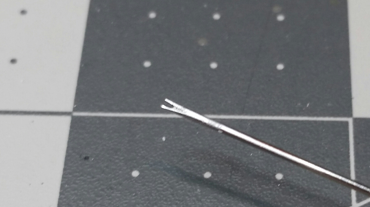
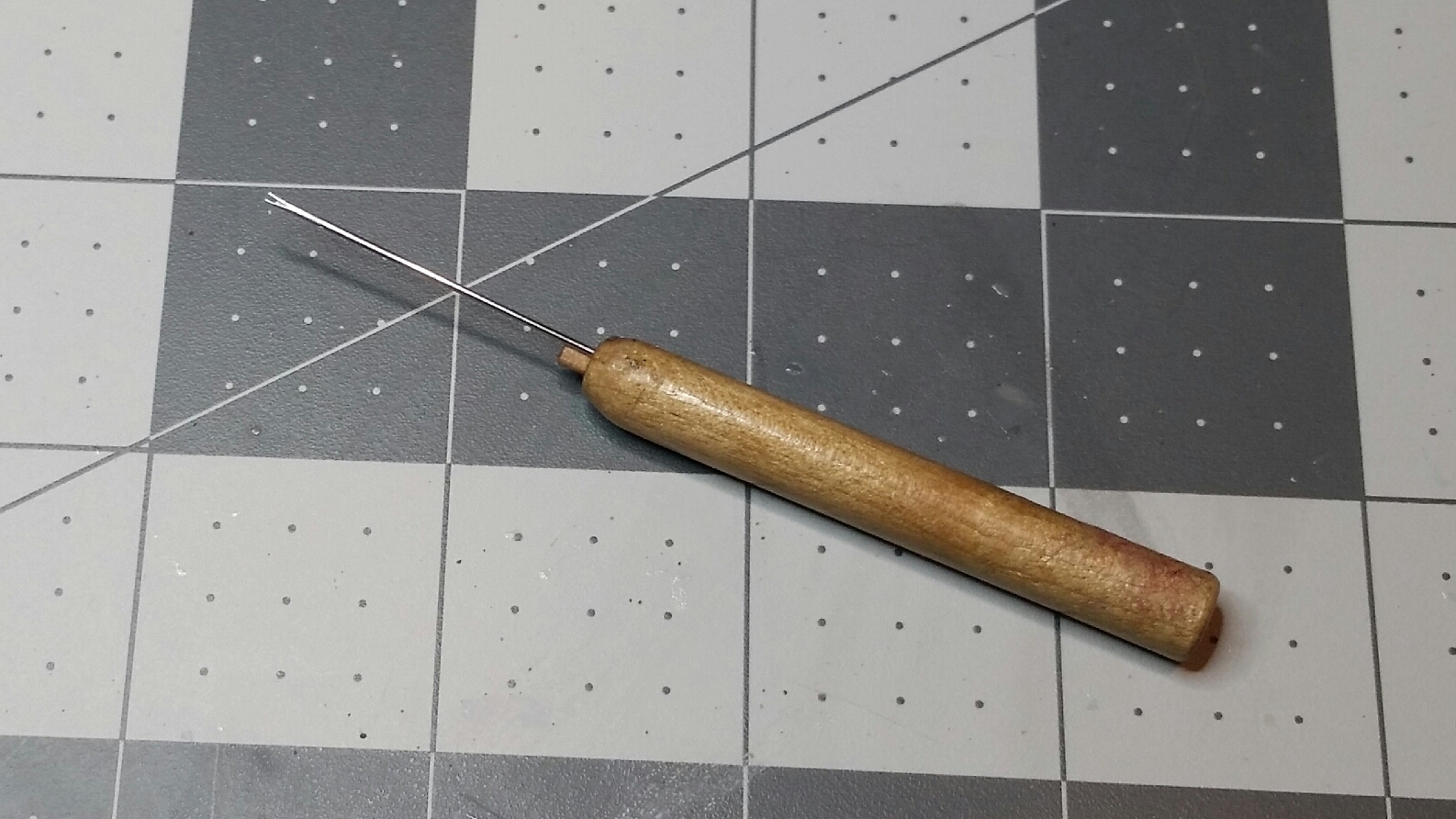
Variation on a theme. Here's a tool I've used for 30 years, specifically for applying super glue. It's a sewing needle that has half of the eye ground away. Dip it into a drop of super glue and hold it adjacent to the desired joint. Capillary action will draw the glue into the joint. Since these needles are hardened it's easy to scrape clean. Hope Dann doesn't mind my intrusion... Take care, Mike

-
1965 Mercury Comet Cyclone (update 1/4/19) Finished!
mecklm replied to RancheroSteve's topic in WIP: Model Cars
Hey, car is looking excellent in paint. From my screen, it almost looks like a hint of blue in the paint? Regardless, that engine compartment is really going to pop against that body color. Doesn't look like too much more work before we see this "under glass". Take care, Mike. -
Thanks for the explanation! The photo clears it up completely. I'd forgotten how much room there is under the rocker covers... Mike
-
Thanks for sharing! I'm familiar with the manifold and hat lines but I'd never heard of lines directly feeding the heads. Can anyone elaborate on how these feed fuel to the cylinders? TIA! Mike
-
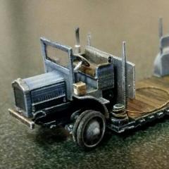
N-scale 1918 Pierce Arrow flatbed
mecklm replied to mecklm's topic in WIP: Model Trucks: Big Rigs and Heavy Equipment
Better late than never, I finally found a way to get the running boards and fenders attached. Thought I'd close out this post with some finished pics. I knew going into this that posting these builds was a stretch on this forum and I've since found a more appropriate group on Facebook. If anyone wants to see future builds you can find them in the group "N Scale Vehicles and Trucks". Thanks to all for following along and I truly hope you got some enjoyment out of these builds. Take care, Mike
-
I have to say you did a masterful job incorporating the throttle body to the inlets of the turbos. I wasn't sure how you were going to pull that off but the final result looks like a factory piece. Well done!
-
The inlets to the turbos are currently connected to each other with that short piece of tubing. I'm interested in seeing how you route the inlet air to that tube. Are you going to try to match up an inlet tube with the existing duct on the top/front of the rear cover? That will be a cool setup when you're finished! Mike
-
Cool woodgrain on the dash! Is that a decal? Mike
-
1965 Mercury Comet Cyclone (update 1/4/19) Finished!
mecklm replied to RancheroSteve's topic in WIP: Model Cars
Yeah, sorry about that if it's making more work for you. That coil on the PS bracket would be easy enough to remove - before the motor goes in the car unfortunately though. It's a detail that the majority of folks wouldn't be able to identify as a coil, but anyone familiar with a 5.0 would recognize right away what it is. Maybe removing the round one from the fender wouldn't be too much of a pain. Other than removing the round coil, the only other thing necessary would be to wire up the front of the square coil, which wouldn't be difficult at all. Regardless of what you do with the coil, the rest of the car is outstanding and I'm looking forward to seeing it "under glass"! Take care, Mike -
1965 Mercury Comet Cyclone (update 1/4/19) Finished!
mecklm replied to RancheroSteve's topic in WIP: Model Cars
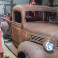
Hey Steve, just checking out the modern front dress that you added to your motor. It seems a bit strange (for a stock F.I. 5.0), but the coil is mounted on top of the tensioner/power steering pump bracket, the square shaped block just to the left of your power steering pump fill tube. I attached a picture of my 1:1 where you can see the MSD coil in the stock location. Same basic shape as what's represented on your front dress. The two prongs on the front of your coil would be where the wires connect - the left prong would be the plug wire going to the center of the distributor cap and the right prong would be the "power" wire coming from somewhere on the firewall. Just thought I'd mention it since you already have an older, round coil represented on the inner fender. Take care, Mike
-
Woods Racing Javelin of George Follmer
mecklm replied to Hooked on Chaparral's topic in WIP: Model Cars
Specific to Woods, unfortunately nothing regarding the engine... http://theamcforum.com/forum/roy-woods-71-amx-trans-am-car-canary-yellow_topic24765.html -
Woods Racing Javelin of George Follmer
mecklm replied to Hooked on Chaparral's topic in WIP: Model Cars
Some info here... http://www.95customs.com/the-1968-72-trans-am-amc-javelins/2015/3/12