10thumbs Posted July 1, 2014 Share Posted July 1, 2014 Hello guys, I'm getting my model kits lined up now for the "to do list". None of these altered or hot rod models have Hilborn Injection. But I know how to make things, so.... What was the size of the injector stacks? I know the length was dependent upon many factors, but what was the general diameter? Was there any difference between the stacks of the A/FX Hemi motors, and maybe a 392 Hemi? What about the SBC's? I have several possibilities for some real nice scale pieces, but I need the diameter, in inches. Thanks, Michael Quote Link to comment Share on other sites More sharing options...
racedriver25 Posted July 1, 2014 Share Posted July 1, 2014 Small blocks ranged from 2-3/16, 2-7/16, 2-5/8. Big blocks were generally 2-11/16, 2-13/16 even some as big as 3". Those are inside diameters. The stacks were generally 1/16th to 1/8th thick. Quote Link to comment Share on other sites More sharing options...
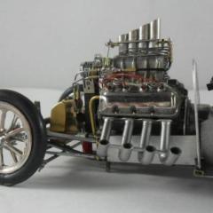
10thumbs Posted July 1, 2014 Author Share Posted July 1, 2014 Excellent Jim, thanks a bunch. So I can use 3mm metal cylindrical tubes for a big block, perfect! I held them up to a 1:25 motor and the 3mm pipes looked about right, but now I'm sure. I just don't want to always have to build blown motors for gassers and F/A cars. I like injected motors on models too. Michael PS: Wasn't Spring Grove, Pa the home of some well known racers from a while back? Quote Link to comment Share on other sites More sharing options...
jwrass Posted July 1, 2014 Share Posted July 1, 2014 Michael, Jim is pretty spot on! It seems like you are curious about injection so throw I'll give you my 2 cents worth. I ran a injected Altered in the 70's. Ours was a Hilborn mechanical drive set up ( no electronics back then) their are many slang terms used in racing and the nomenclature can be a bit confusing. Velocity Tubes (stacks,tubes, ram tubes yada yada) played a very important roll in the tune up, the diameters were fixed based on the manifold you had but you could fine tune the injection with tube length a term called ram tuning, the flare or horn at the top of the tube played a factor as well. Contrary to what some people think the mixture (air/fuel) was not rammed buy momentum as it traveled down the tube, the theory of the tubes was to get the air to flow into the manifold in a wave form vs linear. The flares or horns were thought to bring in the air into the manifold in a smoother fashion much like water swirling down a drain ( you don't have to run stacks to make injection work and many didn't) Part of the tune up equation was the fuel metering orifice or pill in the fuel line. The scientific equipment we had to help in the tuning process were a barometer, thermometer, a nifty Hiborn card stock slide tool to match air temp and atmospheric pressure, reading the spark plugs, cloud cover and a wet finger in the wind. I found it fun and challenging to get a good tune up back then. We didn't have laptops or electronics to measure how the engine performed on a pass, it was by feel, educated guess and the SWAG factor. those were truly some great times. I know this was a bit off topic but it seemed like you had a interest so I shared, jwrass Quote Link to comment Share on other sites More sharing options...
10thumbs Posted July 1, 2014 Author Share Posted July 1, 2014 YES! Guys, this is some very fine first hand talk here. We can look a lot on the web for info, but here on a model car forum we're getting real race car info! I'm ....flabbergasted! lol. (Sorry for the word, my recently deceased Mom had a wonderful vocabulary). I'm happy. I understand now a bit that the tubes were supposed to swirl the air, and not meant to let the injectors breathe pure air rammed in like in a front scoop. Cool. @jwrass, "diameters were fixed based on the manifold you had". What would determine the manifold size to begin with? Would the manifold size be according to the intake size of the head, or of the power that a racer was looking to get? Was there back then such a choice of sizing? Or was the injector manifold, or more of a bar type application as far as I can tell, more of a standard size. Meaning small block,or big block? I like this kind of stuff. Very good background info from guys that know. Good info for model car guys too! Thanks for your interest, Michael Quote Link to comment Share on other sites More sharing options...
Ace-Garageguy Posted July 1, 2014 Share Posted July 1, 2014 (edited) "@jwrass, "diameters were fixed based on the manifold you had". What would determine the manifold size to begin with? Would the manifold size be according to the intake size of the head, or of the power that a racer was looking to get? Was there back then such a choice of sizing? " -------------------------------------------------------------------------------------------------------------------- When you bought an F.I. manifold from Hilborn (or Kinsler or Enderle, other builders of similar systems and components that ran on Hilborn's principles), if you got a manifold for a smallblock-Chevy, you got a manifold designed by Hilborn to work with smallblock Chevy ports, etc. There were often a couple of different configurations available for a particular engine, but I don't personally recall having any "options" on intake-runner or injector-body diameter. Obviously, a 392 Hemi is going to have much larger ports than a 283 Chevy, so the injector bodies and velocity stacks would be sized accordingly. jwrass is spot-on about tuning the old systems. Having a "feel" for tuning was a lot more fun than having a black-box to play with...it just isn't as fast. Do some image searches for the old MFI systems, and you'll find many many photos that you can obtain correct in-scale dimensions from if you take time to figure out how to interpret them. Here's a little more scientific info on the theory of "ram tuning". It's relevent to both intake port-runner length, and to "velocity stack" or "ram tube" length... Visualize the intake cycle of the engine as air flowing down the velocity-stack, through the injector body and intake manifold runner, past the intake valve, and into the cylinder. Everything is fine and dandy until the intake valve shuts. Here is where the concept of inertia becomes important -- because the air was in motion, it wants to stay in motion. But the air can't go anywhere because the valve is shut so it piles up against the valve like a chain reaction accident on the freeway. With one piece of air piling up on the next piece of air on the next on the next, the air becomes compressed. This compressed air has to go somewhere so it turns around and flows back through the intake manifold runner in the form of a pressure wave. (When it hits the open mouth of a velocity-stack, the pressure wave reverses, almost as if it had hit a solid obstruction) This pressure wave bounces back and forth in the runner and if it arrives back at the intake valve when the valve opens, it is drawn into the engine. This bouncing pressure wave of air and the proper arrival time at the intake valve creates a form of "supercharging". In order to create this supercharging effect, all of the variables have to be aligned so the pressure wave arrives at the intake valve at the right time. This combination of synchronized events is known as a 'resonant condition', and many variables can effect the exact necessary length of port or tube to get the desired effect at the desired RPM. There's a fair bit of math involved to make it all work, and the length of the ram-tubes only work WELL in a particular RPM range. Generally, short tubes work at high-RPM, and long tubes make more power at lower RPMs. Edited July 1, 2014 by Ace-Garageguy Quote Link to comment Share on other sites More sharing options...
racedriver25 Posted July 1, 2014 Share Posted July 1, 2014 (edited) This area is well known for a lot of racers in different categories of racing. Rte. 30 Dragway was a hot bed for drag racers back in the day: Bill Jenkins, Jere Stahl ( Stahl Headers), etc... And sprint car racing is huge here, the best in the business run and ran here. To add to the injection discussion I build sprint car motors and we still use mechanical fuel injection on these motors. Hilborn,Kinsler and Engler are the biggies now. Although Hilborn is not real popular anymore on the sprint cars. Tuning can be tricky but common sense usually helps. A weather station, and a good engine dyno are my preferred tools to get these things right. Mainly because if your a slight bit off...... with the compression we run in the 410 motors........ your melting some pistons. Many factors come in to tuning,main pill size,nozzle size, high speed pill size and pressure, secondary pill size and pressure,nozzle length and stack size and length. As stated short tubes tend to increase high rpm power at some low end torque expense, but they tend to make the engine more "driveable". Common practices now are to run a large diameter injection....say 2.9 to 3.0 and run reducer stacks like 2.13/16 or 2 11/16 on the 410's on smaller cube engines we run 2 1/2 or 2 5/8 with reducers as small as 2 3/16. Top end HP is not affected as much as you think doing this and by doing this the engine "squirts" of the corners and on restarts much quicker and smoother. One final thing which was touched on shorter tubes and bigger diameter generally means more top end power less torque, taller stacks more low end torque slightly less top end HP. Smaller diameter tubes tend to make more torque down low also. These are only generalizations because some engine combos can throw the normal out the window. Edited July 2, 2014 by racedriver25 Quote Link to comment Share on other sites More sharing options...
jwrass Posted July 2, 2014 Share Posted July 2, 2014 (edited) You guys are good!!!!!!!!!!!!!!!! I was the owner and shoe of the car. I'm a decent wrench but a far cry from a engine builder, I can put one together and make it live but I didn't have the machine shop to balance and blue print the motors so for me I used to have the short blocks built by a speed shop however we did all of the top end assembly and routine maintenance. One thing I did enjoy was working with the fuel systems, I think it was because I liked all the variables of either getting it right and the risk of getting it wrong $$$$$$$$. Bill, The first version of the car we ran a 421 Pontiac NASCAR motor which was very popular in the drag scene back then. Hilborn made a direct bolt on manifold for that combination with recommended head, valve train components and mag specs. We worked outside the box a bit and opened up the intake and exhaust passages and put The biggest valves in that would fit. We really didn't have to calculate for the effects of fuel cooling as we lit the fire did the burnouts and made the pass. The engine didn't see much run time vs other forms of racing so we ran hot plugs, lots of spark and as lean as we could without killing it. We did however fill the cooling passages with water and would run and time the motor about 15 minuets before we ran as to bring the engine temp close to what we needed to make a pass. Between rounds we drained and refilled the block and did the same procedure as listed. Hilborn was great to work with back then, they helped us though the whole build process and I would call them on a regular basis as I worked on the fuel systems on the car and had many questions and much to learn. I do remember that Hilborn would make sub manifolds that mated injectors for non direct bolt on's. I'm far from a physics major but yes there was some math involved in the tune ups. Being the fuel guy and ram tuner I do remember one equation and I don't know why because it's really useless information to me now it's L=TV over S. L= intake passage length, T= time in crank degrees, S= rpm at horsepower peak, V=1100 fpm. or something to that effect. The only thing that was a question mark for us was the S as their were not many Dynos out there back then but we had a pretty good idea of what kind of horse power we were making so we swaged it, we ran well and never broke a bottom end. Jim, Impressive resume, I crewed on a 360/410 car about five years ago and am familiar with those fuel systems and they really aren't much different than what we ran years ago. My weather station was a glass hour shaped barometer with a red dyed solution that came in a velvet lined hard wood box, and a thermometer. Your tune ups are much more complicated than ours were with the drag car. You have to deal with long term engine longevity, very high torque loads and making it happy and fast all night long. I agree with your tuning assessment a little black magic and common sense. Almost a art form in my opinion with mechanical injection, I wish I had access to a dyno back in the day. My hats off to you!!! go get em great insight gentlemen on a most interesting topic, jwrass Edited July 2, 2014 by jwrass Quote Link to comment Share on other sites More sharing options...
Dale W. Verts Posted July 2, 2014 Share Posted July 2, 2014 And you could easily, with the slightest miscalculation (especially in cool weather) dial yourself right out of the game. Dale Quote Link to comment Share on other sites More sharing options...
jwrass Posted July 2, 2014 Share Posted July 2, 2014 Dale, Been there more times than I care to count. But you can make some BIG ponies on those nice cool fall days Quote Link to comment Share on other sites More sharing options...
fitforbattle Posted July 2, 2014 Share Posted July 2, 2014 Now THIS is why I love reading the Q's and A's. The amount of knowledge, and experience, and willingness to help is amazing. The stuff you speak of and the way you guys do it, all for the sake of helping with accurate model building, blows my mind. Quote Link to comment Share on other sites More sharing options...
10thumbs Posted July 2, 2014 Author Share Posted July 2, 2014 Hi Robin, You're absolutely right! Great info. I'm really pleased to get some inside look into these things. Blowers are cool, but I want Hilborn-Type injection. I looked on YouTube and found one Kinsler injection setup, on the dyno. The engine made 800hp, but amazing was, at idle, the amount of gas going in to each stack! Jeez, I'm not talking about a spray, I'm talking about a solid stream of gas! Not a setup for the thrifty minded.... Michael Quote Link to comment Share on other sites More sharing options...
Recommended Posts
Join the conversation
You can post now and register later. If you have an account, sign in now to post with your account.
Note: Your post will require moderator approval before it will be visible.