dptydawg Posted December 15, 2009 Share Posted December 15, 2009 (edited) INVERHURON DIESEL GENERATING STATION Some time ago I acquired this model The bonus item is the V10 Genset load in the trailer. I also acquired the Norscot 1/25th scale diecast model of the Cat 3516B Genset. To me it was a natural to build a Diesel Generating Station diorama using these two models as the key elements.I have worked in a nuke power plant for 30 odd years and I figured it was time I had my own little generating station. It will be known as Inverhuron GS. I came up with an old record turntable cabinet to form the dio base. This fixed the dimensions of the dio and the number of elements that could be included in the dio. The Cat model is a self contained skid mounted genset. It only requires some detail painting and it could be dropped into the dio. The Revell V-10 on the other hand is a very basic engine. It will need numerous bits of auxiliary equipment to get it to a replica of a running machine. After much searching around the Internet I believe that Revell modeled this engine from a V12 Sultzer Genset. For some reason they lobed off a couple cylinders. Probably so it would all fit in the box. By the time I had tracked down this information I had already painted my engine cobalt blue instead of their alpine greenish colour and will leave it that colour. This is the basic layout that I came up with The floor is a suspended ceiling tile on a particle board base. The notch in the right corner is the outside area. The Cat rad will sit in the wall. A cooling tower for the big engine will also sit in this area. The auxiliaries for the V-10 will sit along the left side of the engine. The walls will be cutaway to indicate that there is more beyond the boundaries of the diorama. This also means that I don't have to model a roof and all the widgets that would be hung from it. A mock up of the walls and cooling tower The gravel lawn has been planted and the concrete piers for the cooling tower are installed. The walls are glued in place and details are being added. The cutaway edges are painted in flat red to highlight the fact that they are cut away Looking out through the opening for the Cat's rad. I've added a controller for the louvers and started to install the electrical outlets. The ladder and catwalk is for maintenance access to the cooling tower via the roll-up door. That's all the progress I've made so far. The build will continue counterclockwise from the cooling tower, to the Cat, To the Sultzer, to the auxiliaries and back to the front left corner. Thanks for looking Carl Edited December 15, 2009 by dptydawg Quote Link to comment Share on other sites More sharing options...
Eric Stone Posted December 15, 2009 Share Posted December 15, 2009 That's pretty cool! Quote Link to comment Share on other sites More sharing options...
Eshaver Posted December 15, 2009 Share Posted December 15, 2009 You 've made a lot of interesting progress since I saw it last on The Model Builders ........ Ed Shaver Quote Link to comment Share on other sites More sharing options...
disabled modeler Posted December 15, 2009 Share Posted December 15, 2009 WOW !!!! that is cool! its going to make an awesome diorama item......super sweet. Quote Link to comment Share on other sites More sharing options...
dptydawg Posted December 17, 2009 Author Share Posted December 17, 2009 Just a quick update. Spent a lot of time today making fiddely bits. I was starting to go crosseyed so I'm taking a break. I've put togeather the control box for the cooling tower. The guages are from the parts box, the handswitches and indicator lights are made from chunks of evergreen rod painted with Tamyia clear red, green or amber. The battery banks for starting the Cat engine came out of both my Western Star truck models. Each one has four 12 volt batteries (I'll have to glue the baterybox covers down tight on them now :ermm: I started to install cables to wire them up for 24 volt output but its not quite done yet. They will sit on the battery stand that I have still to paint. Each battery will supply one of the starter motors Thanks Carl Quote Link to comment Share on other sites More sharing options...
randx0 Posted December 17, 2009 Share Posted December 17, 2009 This is really cool.I am enjoying watching the progress . Quote Link to comment Share on other sites More sharing options...
charlie8575 Posted December 18, 2009 Share Posted December 18, 2009 Neat project. Charlie Larkin Quote Link to comment Share on other sites More sharing options...
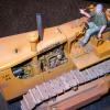
dptydawg Posted December 27, 2009 Author Share Posted December 27, 2009 I've been working on the Cat Genset over the holidays. Its now glued to the base. Ive added some fire sprinklers, a fuel supply line and exhaust stacks. Here are a few pics Thanksd Carl Quote Link to comment Share on other sites More sharing options...
dptydawg Posted January 4, 2010 Author Share Posted January 4, 2010 Since the last update I have finished with the Cat genset. The battery rack is now glued in and the cables attached to the starter solenoids. I have been struggling with the cooling water plumbing for the big engine. Since this is a fictitious engine then there is no specific prototype to follow. I'm trying not to let the laws of heat and thermal or fluid mechanics get in the way of a good story. But I am trying to keep the final product believable (I hope) The biggest problem I have is finding wide radius elbows for the piping. This is a pic of the inlet and outlet headers before painting. Most industrial plants use colour coded piping to identify the contents. While there is no universal standard I'll be using the old Ontario Hydro standard colour coding. Red = fire suppression, Yellow = oil systems including diesel, Blue = air, Green = water. Black = waste water and silver = steam. Electrical conduits are normally natural metal colour. The cooling water outlet headers have been installed on the block along the top of the intake log manifold. The outlet of the intercooler is also tied into this header. The valves are made form plastic beads with handles added. The inlet pipes are maybe sitting in place along side the exhaust manifold. I'm still trying to decide how best to route these pipes. Thanks for looking Carl Quote Link to comment Share on other sites More sharing options...
Sixties Sam Posted January 5, 2010 Share Posted January 5, 2010 That's something really different and it looks great, Carl! Excellent detail work. I can hear that diesel running now! Where are my earplugs?! Sam Quote Link to comment Share on other sites More sharing options...
Tony T Posted January 11, 2010 Share Posted January 11, 2010 Very nice so far! Quote Link to comment Share on other sites More sharing options...
dptydawg Posted January 14, 2010 Author Share Posted January 14, 2010 A bit more work to show When I started to put the cooling water lines in for the genset I quickly realised that I had to install the cooling tower. I needed to have a reference point to run my piping from. So I finished up the yard under the tower and installed the suport structure. addded some hold down bolts and a little rust here and there. I added some power and control conduits to the cooling tower and installed some safety screens over the fans. The roll up door has done so for this shot. The expantion joint was machined form a plastic knitting needle (one of my favourite raw materials) The finished cooling tower. Thanks Carl Quote Link to comment Share on other sites More sharing options...
dptydawg Posted February 18, 2010 Author Share Posted February 18, 2010 Its been a month since I last did an update on my genset project. I have been making some progress on it. The cat is essentially complete. Most of my time has been adding details to the Silzer engine. The yellow piping coming out of the floor is the fuel supply. It goes into some filters and through scratch built injector pump to the blue (engine coloured) fuel system piping. The other yellow pipes (top and background) are for the lube oil system. The generator was then installed . I added power output and control cable conduits to the generator. The windings of this generator are water cooled. To ensure very pure low conductivity water the piping is all copper. The heat exchanger is a plate type and the purification ion exchange columns are under the gray control panel box. Some of the equipment is located off stage. The piping ends at the base's edge. The engine uses a drysump lube oil system. Oil drains via gravity from the bearings to a sub-floor storage tank. It is then pumped via a gear type pump through another plate HX to a filter then back to the engine and gen bearings. The filter is made from a Nascar fuel can. The green pipes are for the cooling water system. I still have to install the cooling water pumps in this are. Thanks Carl Quote Link to comment Share on other sites More sharing options...
Eshaver Posted February 18, 2010 Share Posted February 18, 2010 Carl, I would have thought you might have given up on this project . Still , you perservered , bravo ! It certainly will draw attention on a contest table . Ed Shaver Quote Link to comment Share on other sites More sharing options...
dptydawg Posted February 20, 2010 Author Share Posted February 20, 2010 Carl, I would have thought you might have given up on this project . Still , you perservered , bravo ! It certainly will draw attention on a contest table . Ed Shaver Thanks Ed. I generally try to stick to one project at a time. I try to complete it before I tackle something new. Otherwise I would end up with a basement full of partially completed projects. Now I just have a basement full of unstarted projects. Besides if I don't finish it I won't have anything new to take to the shows this spring. Thanks Carl Quote Link to comment Share on other sites More sharing options...
disabled modeler Posted February 20, 2010 Share Posted February 20, 2010 Way too cool! they need to offer the generator system w/o the trailer Would be a great place to hide batteries for diorama lighting. Quote Link to comment Share on other sites More sharing options...
dptydawg Posted February 28, 2010 Author Share Posted February 28, 2010 I thinnk that the last of the plumbing has been run. I finished adding the pumps and control valves for the cooling water circuit. The painters still have to add some dirt to various places to make it loopk used. and the millwrights still have some pipehangers to install. The I&C techs have a bunch of control lines to run and some instrumentation to install. This power station is close to going on line. There is still more work to be done to the operators before they are ready for duty. Thanks Carl Quote Link to comment Share on other sites More sharing options...
Old Albion Posted February 28, 2010 Share Posted February 28, 2010 Carl, This is a truly magnificant project. Being an Engineer I can relate to the things you mention. It has been a real pleasure to read through your description and seeing the photo's of the progress. Many thanks for sharing this with us. If you need parts and materials for building factories and such like. Try this company. They are based in the UK but there will be companies like this in the USA and Canada. http://www.ema-models.co.uk/ Best Wishes Dave Quote Link to comment Share on other sites More sharing options...
dptydawg Posted March 1, 2010 Author Share Posted March 1, 2010 Thanks for the kind words, Dave. It is a fun build. Since thee is no exact prototype to follow it is an evolving diorama that looks nothing like I had in mind when I started to plan this thing out. We have a Canadian source for modeling supplies http://www.modelbuilderssupply.com/ their website has the feel of the one you gave me from the UK. There is a few more tweeks to do to the diorama before a show this Sunday. With that deadline in sight , this thing will be finish very soon Thanks Carl Quote Link to comment Share on other sites More sharing options...
dptydawg Posted March 2, 2010 Author Share Posted March 2, 2010 Here is a labled photo of some of the components that form my power plant dio I'm not sure how legible it will be but hopefully it will explain why some of the things are there . Thanks Carl Quote Link to comment Share on other sites More sharing options...
Recommended Posts
Join the conversation
You can post now and register later. If you have an account, sign in now to post with your account.
Note: Your post will require moderator approval before it will be visible.