SpreadAxle Posted May 1, 2007 Share Posted May 1, 2007 I took a break from the Autocar as I didn't want to rush the final details, so I started the drom box for this truck. Just waiting for the putty on my rear wall halves to dry so I can finish the assembly. I made it 7 scale feet long using the AMT Ford Louisville Shorthauler body to put this one together. I got the inspiration for making the drom box this way from this truck that I believe was on Tim's website. the only difference is mine only has a door on the passenger side. I don't know how it's set up on the Allied van, but I know there is no door on the driver's side. here's another shot.... I cut both side walls in the same spot. The smaller sections of the leftovers were put together to make the rear wall. While I waited for the putty to dry, I worked on the Autocar's interior. I still have to sand the rear wall a little, make some corner sections, and cut the roof to length, but I feel good having started it. I'll post pix of the cab modifications I made 2 weeks ago as soon as I take some shots. I 4got to last time. All I did was cut the sleeper in half, but I still have to figure some things out with it. I don't think the cab shell will be very hard, but the engine mounts, and interior are what I think will be the challenge, as the engine is under the drom box, and the cab has a flatter floor. Keep watching, it will progress. Thanks 4 looking Oh yeah, before I forget, anyone with some more info to share, please let me know. Feel free to add to my post in 1:1 Truck reference as well. I'm sure others would like to try this one. This is one of those trucks with virtually no information to find. Thanks again Quote Link to comment Share on other sites More sharing options...
Old Albion Posted May 1, 2007 Share Posted May 1, 2007 Ray, With reference to the flat engine. The cummins and any other straight six engines is going to be quite tall. I assume that the engine sits flat below the frame. Is that why the turbocharger is on the side rail to give more clearance between the ground and engine. There would probably be a removeable floor panel in the bottom of the drom box??? Not much use when the truck is loaded. Exhaust Manifold to the bottom???? to keep the heat away from the drom and its load. The engine mounts hmm! Interseting problem. Will there be 3 off them to get the triangulation so the engine is always supported. Two will most probably be at the rear of the engine with one at the front. I assume all the mountings will be on the block only. This will allow for easy removall of the head, pistons etc when servicing and overhauling. The shape of the sump will need to be considered so that the oil pick up is at the lowest point and in the oil. One thing I havent quite worked out yet is whether the engine when looking from above is on the centre line of the two frames or whether it is offset. If it is on centre then there is a nice snug place for the bell housing and flywheel between the frames. If it is offset the engine will need to be lower for the bellhousing to clear the frame rail. My guess is that the engine is on centre between the rails. This makes much more sense. When you consider taking on a project like this with limited information. A lot of artistic license is needed. If you look at the vehicle from three aspects it may help you to resolve some of the build and design isses. 1. When freightliner built this truck how did they assemble it. 2. How did the driver drive it and how did he operate it? 3. How did the maintenance Engineer carryout routine and breakdown maintenance. This is an excellent project Ray and wish you well. Keep us posted on progress. Quote Link to comment Share on other sites More sharing options...
SpreadAxle Posted May 1, 2007 Author Share Posted May 1, 2007 Here is a brochure pic of the engine, basically the kit engine laying exhaust side down as you mentioned. WHen I was in school, I was told some buses used a model like this also. Quote Link to comment Share on other sites More sharing options...
SpreadAxle Posted May 2, 2007 Author Share Posted May 2, 2007 Oops. :oops: The engine is intake side down. You made an excellent point concerning heat, but then I remembered, the intake side of the engine was the bottom when installed this way. I looked at the pic in my post in 1:1 reference, and realized I said that wrong. Thinking about it, I wonder why the exhaust side would be facing the bottom of the body. hmmm. Quote Link to comment Share on other sites More sharing options...
SpreadAxle Posted May 4, 2007 Author Share Posted May 4, 2007 Well, the rear wall and it's corner fillers, plus the roof, are now installed. This was a fairly easy build. Next step is the engine. I at least want to start on the basics anyhow. A coat of primer goes on this weekend. Liek I said, this is one of those in between my other project kind of builds as it has to wait on me to gather info. Thanks for looking. Quote Link to comment Share on other sites More sharing options...
monkeyclaw Posted May 7, 2007 Share Posted May 7, 2007 Dave; I spoke with engineers at cummins about this very project.....it was indicated to me that the NHHT was actually mounted at an 80 degree angle between the frame rails...the peterbilt prototype trucks used a "fishbelly" frame for this mounting, which had a large hump in the frame, so the motor assembly could be slung beneath the frame. The freightliner actually mounted the turbo unit to the outsdie of the frame, at quite a distance from the manifold....matt Quote Link to comment Share on other sites More sharing options...
SpreadAxle Posted May 8, 2007 Author Share Posted May 8, 2007 Progress is going slow but steady on this one. Stripping a gluebomb with several THICK coats of paint is a challenge. The frame is in the process of being stretched. The engine has been started. I will post pix later of it. Quote Link to comment Share on other sites More sharing options...
Old Albion Posted May 8, 2007 Share Posted May 8, 2007 Matt, Interesting comments about the 80 degree engine and the frame rails. From your comments it looks like one or two of the other truck manufacturers built a similar truck??? This is one of the projects that really interests me. The research, the engineering, scratch building, yes it has it all. I'm really looking forward to seeing Ray's progress in the weeks or even moths to come. Its a big project, but having seen Ray's Autocar and his dedication to his hobby I have no doubt that this will be a great rig when finished. Good Luck Ray. Quote Link to comment Share on other sites More sharing options...
SpreadAxle Posted May 8, 2007 Author Share Posted May 8, 2007 Thank you Dave. I've been sort experimenting and test fitting, mocking things up. I'm really looking forward to doing some assembly. Quote Link to comment Share on other sites More sharing options...
SpreadAxle Posted May 9, 2007 Author Share Posted May 9, 2007 This truck during various phases of construction will be subject to builder interpretation due to limited info on these Freightliners. The engine is one of them. I only have one view of this engine in the 3 pictures I have. Always from what would be the left side of the truck as it sits in(sort of below) the frame. (see my post in 1:1 reference and all 3 pix are there). I am building the turbocharged version. The oil pan was made using a piece of sprue glued in the center of where the kit oil pan normally would go as a guide. Squadron green putty was then poured over it and shaped. It's what seemed to be right to me, although I may need to round it off some more. Also, the edges were cut off of the kit's pan, to preserve the bolt detail, and placed on the edges of my homemade oil pan. The air compressor and fuel pump are moved to the front of the engine. The aftercooler is also moved forward ever so slightly, to being just past the heads. The water manifold was modified to accomidate the thermostat housing. The way the engine is laying is how it will look installed. I still have to install the oil pump, and also figure out if the frame mounted turbo sits on a plate, or if it's directly mounted to the frame. That will tell me where to go with the pipe that leads from the exhaust manifold to the turbo. Meaning through the frame, or is the pipe routed down, and then under the frame. The pipe from turbo to intake is clearly visible in my reference pix. The only other things to figure out is where the oil filter and the alternator are located. The Willamette Valley Freight lines truck in the 1:1 reference section shows the naturally aspirated version. Thanks to Matt Burnett for all of his help with this project. He has been a big help. Thanks to him I discovered the oil pan is rounded, following the arc of the crankshaft. Hence the putty oil pan. Thanks for looking. Quote Link to comment Share on other sites More sharing options...
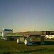
SpreadAxle Posted May 9, 2007 Author Share Posted May 9, 2007 Dave, here is a pic of Peterbilt's experimental version of this truck. Tim would know more, but it's my understanding that this truck wasn't placed into production. I'm not sure if a prototype was built or not. Quote Link to comment Share on other sites More sharing options...
SpreadAxle Posted May 9, 2007 Author Share Posted May 9, 2007 Here is the sleeper that will eventually sit above the cab. You can see what I mean as to how thick the paint was. I cut just above the side compartment doors on the sleeeper. Quote Link to comment Share on other sites More sharing options...
Recommended Posts
Join the conversation
You can post now and register later. If you have an account, sign in now to post with your account.
Note: Your post will require moderator approval before it will be visible.