BSteinIPMS
-
Posts
48 -
Joined
-
Last visited
Content Type
Profiles
Forums
Events
Gallery
Everything posted by BSteinIPMS
-

Articles now being paid for?
BSteinIPMS replied to BSteinIPMS's topic in Model Cars Magazine News and Discussions
Hi Larry, Your response was measured and well written and I appreciate your sentiments. I, too, hope MC gets back on track financially and - with your help - is restored to its former glory. My original post wasn't written out of festering bitterness, but rather as an advisory for prospective writers to be aware of the past, otherwise we can't learn from it. I would hope future writers for MC have a signed contract, or an e-mail confirmation of same when they submit articles so that agreement exists on both sides and good will continues to flow. Without intending to cause dissention on what should be a fun and uplifting forum I would submit that I am under no obligation to provide any proof of what I've written since this is not a court of law. Besides, I've let it go long ago since I choose to not allow negativity obstruct the fun things in my life. I might also say I've received several e-mails and Private Messages from past writers who have had the same experience as I have. I know Mr. Hutchings has had dire physical problems in the past and I have empathy for this. I might also observe that integrity is a fragile thing. Once you've given it away it's difficult to restore it. Best of luck as Associate Editor and let the good times roll. On four wheels. Cheers! --Bob -
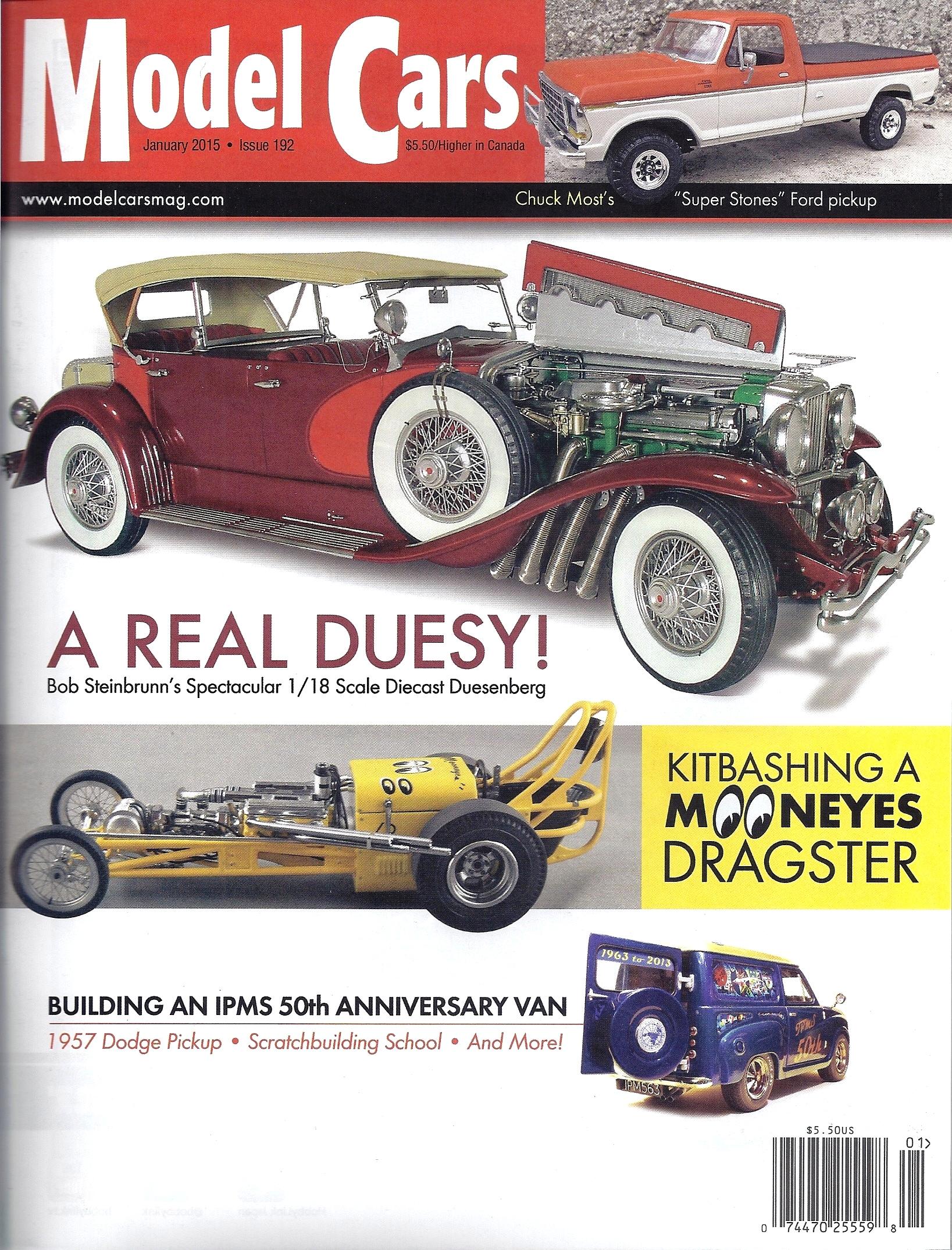
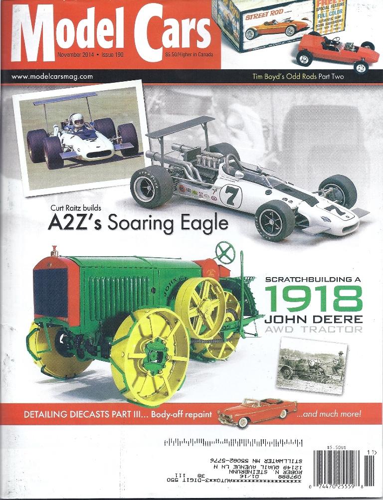
I always thought MC was a class magazine, especially after the grand treatment Harry Pristovnik gave my 1929 Duesenberg SJ article in MC Issue 192, January 2015. On the cover, too. Thus inspired, my next article was on the John Deere 1918 All-Wheel-Drive Tractor which appeared in the November 2014 issue. On the cover, again. However, I was never paid for that article, and upon several e-mail inquiries I was told by Mr. Hutchings that it was too late to pay me: MC was a small family business, money was tight, and he needed back surgery. My response was that MC depended on good articles. Good articles come from good modelers. Good modelers continue to write articles based on trust that the publisher will remunerate them. Publishers who renege on payment lose their integrity. Loss of Integrity means good modelers will no longer write articles for MC and will send them elsewhere. Me? My last two automobile articles went to Kalmbach’s Scale Auto, and they not only did a fine job, but paid for the articles as well. I guess I learned MY lesson. Cheers! --Bob Steinbrunn

-
Hi Pat, It's a photoetch kit from The Model Car Garage, and it replaced the overscale hinges on the Revival kit.
-
...and thanks to everyone for all the kind comments! Much appreciated!
-
Hi Tom, Certainly, be glad to. An inside view of the hood showing the piano hinge. Since the inside of the hood was devoid of detail I added reinforcing strips around the edges of the hood made from Evergreen .010” x .020” styrene strip with Tichy Train Group .020” rivets. Having done that, I decided to add all the louvers from the same strip styrene which were shaped after the individual strips were glued down.
-
You have a great suggestion, Skip, thanks! Actually I sanded the rubber tires down to scuff them up and remove the mold seam around the circumference, but I stopped short of removing all that lovely tread pattern. Couldn't bring myself to tear it all off since the spoked wheels and tires are two of the highlights of the kit. Cheers!
-
Well, it's finished. This Alfa Romeo monoposto Tipo B P3 in 1/20 scale by Revival International in Italy took 252 hours spread over 9 months and has 2521 parts and pieces. Lots of fun and a well-engineered kit, with the possible exception of the fact that virtually none of the parts fit. You hafta make 'em fit. But then, we're modelers, right? Not just "kit assemblers". A right side view showing the silver fuel and oil lines along the frame, the latches in the fuel, oil, and radiator caps made from brass strip inserted in drilled-out holes, and the mechanical brake linkage underneath the car. This rear view shows the complex semi-eliptic springs and friction shock absorbers on all four wheels. The shocks were a challenge to scratch-build but really add significant detail to the model. This close-up of the cockpit reveals the Alclad II Aluminum interior, the leather seat, wood steering wheel, and the instrument panel. This is a triple laminate and was made using an old model airplane technique. The outer or front panel was cut to fit from .010” sheet styrene and the instrument holes were drilled and filed in. The center laminate section is a piece of clear acetate cut from a page protector and will look like glass when assembled. The rear section is another piece of .010” sheet styrene that had the kit’s instrument decals applied to it. When all three sections are joined together the look of gauges under glass is very realistic. The complex semi-eliptic springs and friction shock absorbers show up well here, as does the beautifully rendered rubber tires with a convincing tread pattern. The right engine bay opened up showing the exhaust manifold, ignition wiring, and the engine starting crank made from .015” brass wire and brass tubing. The hood and engine bay doors are designed to be openable, creating great access to the engine. The 2.6 litre straight-eight engine produced 190 hp using two Roots-type superchargers. The kit’s hood and side engine panel were devoid of detail, so all the louvers, sheet metal, and rivets were added. The model sits on the base of its display case with the spare engine on its stand and a Cloisonnè Alfa Romeo badge procured online which provides a little atmosphere.
-
Alfa Romeo Tipo B P3 (1937)
BSteinIPMS replied to BSteinIPMS's topic in WIP: Other Racing: Road Racing, Land Speed Racers
Hi Scott, No, there is no ferrous metal in the kit, just white metal, brass, and the tiny steel screws. Having said that, though, everything gets airbrushed with Floquil. Cheers! --Bob -
Aw, c'mon....you guys are embarassing me! Thanks for all the kind words from everyone; much appreciated! In this case, though, I think the magic Harry Pristovnik performs with his stunning layouts makes a nice model look better. One of the fun aspects of modeling cars from this era for me is to try to replicate an actual car. Like many of you on this forum, I think I'm at the level of....if I can see it, I can make it. Documentation and photographs are a must for this, of course, and I have to thank the Auburn Cord Duesenberg Museum in Auburn, Indiana, for the archival assistance of Jon Bill who sent me beautiful 8" x 10" color glossies of the actual car I modeled. It was no longer at the museum but they had the foresight to photograph it completely. This makes a modeler's job easy and more fun. Cheers! --Bob
-
Hi Andy, At the Twin City Aero Historians meeting on Saturday 14 Feb 2015 one of the members gave me a metal 1/24 Wills Vauxhall 30/98E kit. After a lengthy inventory I found all the pieces are there, so google brought up this interesting information: Bob Wills started producing these kits in England in 1955 (!!) and for the time they appear to be excellent. Not too bad now, either. He later sold out to South Eastern Finecast who produce a wide range of car, locomotive, and structure kits in various scales. They list my Vauxhall kit at £65.79, about $100.96 today. Not a bad gift! Oh, and your Bugatti is lovely. You're better than you tell me! Cheers! --Bob
-
Alfa Romeo Tipo B P3 (1937)
BSteinIPMS replied to BSteinIPMS's topic in WIP: Other Racing: Road Racing, Land Speed Racers
Well, both engines are finished and have 1020 pieces between them. One will be mounted in the car while the other will be displayed on its stand next to the finished model. You gotta love that Alclad II. These kits from Revival Models are best tackled if you're an intermediate or advanced modeler, mostly because there are no instructions per se. Just several exploded drawings which task you with deciding on assembly sequences and which screws go where. Still, I'm having great fun with this. -
Thanks to everyone else for your kind comments. Hope you found something useful here! Cheers! --Bob
-
Hi Joe, Glad to. The way I made these spark plugs was this: 1. Cut sections from Plastruct hexagonal styrene rod for the bases of the plugs. (This product comes in several sizes.) 2. Chuck a section of the appropriate size styrene rod in your Dremel and turn the ceramic portion of the spark plug using files. 3. Drill a hole down in the top of this rod and insert a short length of brass rod which becomes the terminal fitting. 4. Using Detail Master wire of the appropriate diameter for your model, strip a bit of insulation from the end and wrap this around the brass rod to make the connection. 5. Paint as desired. Cheers! --Bob
-
Detail Master .012" gray Ignition Wire is being used to add the spark plug wires running to the magneto. Detail Master makes a wide variety of wire in various diameters and colors. The hoses for the engine's cooling system were made up from insulation cut from electrical wire. The copper wire strands were removed, leaving just the hollow hose. Photoetch stainless steel hose clamps from Detail Master completed the realistic look of the hoses. The open hood reveals the McVicker 4-cylinder engine of 24 hp. The two access plates on the crankcase are held in place by a clamp. On the rear bulkhead is the vacuum-driven fuel pump, a large accessory. Four lubrication lines emerge from the cooling jacket which carry oil to the pistons. These lines originate at the mechanical lubricator positioned on the engine's left. The forward side of the engine bay contains the fan, fan shroud, and an oil can held in its three-fingered mount. The upper radiator hose running to the water inlet fitting on the engine is evident. The operating hood latches may be seen, along with their hook-shaped retainers. The open left engine bay reveals the four spark plugs at the top of the engine, the spark plug wires running through a conduit, the exhaust manifold, the intake manifold, the carburetor with the segmented steel hose leading to the air cleaner with its sediment bowl, and the mechanical lubricator in its brass housing. The forward section of the engine bay shows the brass magneto mounted on a bracket on the engine and the magneto drive coupling running forward to the gearbox. Below is the water pump with its coupling and green grease cup. The eight oil lines emanating from the mechanical lubricator were made from copper strands pulled from electrical wire. Well, this concludes this tutorial, and I hope you found something useful in all this even if it is a lowly farm tractor. Cheers! --Bob
-
The right side of the engine showing the vacuum-driven fuel pump attached to the bulkhead on the left, the oil can on the frame in the center, and the oil can holder just to the right of the can. The stabilizing rods can be seen running from the bulkhead to the bolt on the engine water outlet fitting, and then forward to the radiator. A right side view with the hood open, exposing the engine. Hood prop rods will be made later. A left side view with the hood open exposing the engine and its accessories. It almost seems a shame to paint the model. Almost. Applying MIG Productions Dark Wash around engine details with a 5-O brush to create depth and shadow. This makes details "pop out" which is a subtle yet effective technique to make all the details more visible and realistic. The use of Micro-Mark's Doc O'Brien's Weathering Powders. The engine exhaust pipe is having Faded Blue pastel applied with a brush to indicate some minor heat discoloration. Rusty Brown and Grungy Gray will give a hint of rust and dust, although the total effect remains very subtle.
-
The pieces for the fan are laid out and centered on a cruciform shape marked in pencil on paper. The fan arms are glued to the hub plate with CA glue. The blades are curved and CA-glued to the arms, then rivets cut from .020" styrene rod are added using liquid cement. The finished fan mounted on the fan gear case of the engine using two sizes of brass tubing: one for the fan shaft which slides into the other - and larger - section of brass tubing in the gear case. This allows the fan to spin and also to be removed for painting separately. A rear view of the fan showing the curvature of the blades and the pitch they have as a result of the fan blade arms being twisted 45 degrees. Notice the spring on the shaft which was on the full-size engine. This spring was made by winding wire around the shaft. The details of the engine's left side include the water pump, magneto, and carburetor. The left side of the engine showing the mechanical lubricator at the lower right in this view. Above the lubricator sits an inlet air filter with a clear dust bowl on its bottom and a metal hose connecting it to the carburetor.
-
Alfa Romeo Tipo B P3 (1937)
BSteinIPMS replied to BSteinIPMS's topic in WIP: Other Racing: Road Racing, Land Speed Racers
Hi Scott, If you have the interest, the Website for Revival Models is: http://revivalinternational.mysupersite.it/ I ordered my kit directly from Italy, along with a second engine they sell separately as a kit. You'll receive a warranty slip with a serial number which you can copy and send back should you need any replacement parts that somehow became broken or lost. My kit arrived well-packaged and in excellent condition, and I did ask for three missing parts which came in about two weeks. Good service. Cheers! --Bob -
The engine is becoming more detailed with the addition of the exhaust and intake manifolds and the gear case on the front of the engine. The brass tubing shaft protruding from the front of the engine fan gear case will have the fan mounted on it later. The part numbers TM 211LH and TM 210RH were added to the right-hand valve chamber covers, just under the intake manifold. A view of the engine gear case. Only the top half of the crankshaft gear housing is seen at the 6:00 o'clock position here. The lower half has already been mounted under the tractor frame and the two halves will mate when the engine is installed, appearing as an integral unit.
-
The details added to the engine block and cylinder head show up nicely here. Nuts, bolts, spark plugs, and other items were fashioned from styrene strip and rod, along with brass rod and tubing. The engine is becoming more fun as details are added. The .125" styrene rod being softened over a candle flame in order to make nice sharp bends. Hold the rod well above the flame, say, three inches to start, and work closer to the flame as needed. Better to be conservative and allow the plastic to warm up gradually to maintain its (unmelted) shape which allows for more precise control of the radius of the bends. The exhaust manifold and pipes were fabricated from Evergreen .125" styrene rod bent to shape very carefully over a candle. The four sections of pipe were cut and added as two pieces that were attached with CA glue. These were sanded to shape when dry. Brass pins locate the manifold exactly in place on the side of the engine block.
-
In the November 2014 issue of Model Cars magazine my article on building a John Deere All-Wheel-Drive Tractor circa 1918 appeared. Since publication limitations prevail, the article spanned only 6 pages. Realistic, I know: who wants to read a lengthy article about a farm tractor in a model car magazine? (grin) Still, there might be some merit in this tutorial on scratch-building the engine which powered this tractor since making an automotive engine - regardless of application - is modeling. Hopefully there is something useful in this tutorial to make it's use of bandwidth redeeming. The engine in question was a lumpy 4-cylinder engine of 12 horsepower at the rear drawbar and 24 at the left-side pulley. This pulley drove various implements and farm machinery via a lengthy belt, and produced more hp since there were no drive losses. Aside from the many photographs I have of the 1:1 engine I also have a period brochure which provides some additional answers to questions I had as well as some flavor and ambiance of the times. The actual engine was manufactured by the McVicker Engineering Company in Minneapolis and the completed engines were shipped to John Deere in Moline, Illinois, for installation in the tractors. Page 1 of 4 of the original brochure. Page 2 of 4 of the original brochure. Page 3 of 4 of the original brochure. Page 4 of 4 of the original brochure. Left: a rough rectangular block laminated up from five sections of .120" sheet styrene. Center: the crankcase section of the engine with hand hole plates held shut by a clamp. Right: the Lion Roar photoetch frets from which the plate part numbers TM 208 were obtained. The four cylinders cut from brass tubing are in place on their base plate, along with bolt pads and Tichy Train Group (model railroad stuff) styrene hardware. Angled fillets made from strip styrene enclose the throw of the connecting rods. These are visible on the right side of the engine only. The left side is covered by a water jacket, part of the cooling system. A Dremel in the drill press with a cutting bit to mill out a portion of the engine block by hand. A speed controller (or rheostat) is essential to avoid melting the styrene. Watch your fingers! Scale Scenics Microfine solder which was used for the cylinder head gasket by lightly pushing it into the groove cut in around the block. This defines the separation of the cylinder head from the engine block.
-
Alfa Romeo Tipo B P3 (1937)
BSteinIPMS replied to BSteinIPMS's topic in WIP: Other Racing: Road Racing, Land Speed Racers
Yes I am, Tom. One engine will be mounted in the car with the hood (bonnet) panels open, and the other will be displayed on the engine stand next to the model on the base. -
Alfa Romeo Tipo B P3 (1937)
BSteinIPMS replied to BSteinIPMS's topic in WIP: Other Racing: Road Racing, Land Speed Racers
You have a discerning eye, Pat. Yes, there are. The final drive from the gearbox ran to an attached differential which then split the drive into two torque tubes housing two propeller shafts which ran back to two bevel gearboxes on the rear axle. The advantages of this design were (1) it offered a slightly lower seating position for the driver who sat between the torque tubes, (2) it allowed a lower unsprung and axle weight since the axle carried no differential, and (3) it facilitated final gear ratio changes to suit various race courses. I've tried to show this using aluminum and brass tubing for the torque tubes and propeller shafts. -
Alfa Romeo Tipo B P3 (1937)
BSteinIPMS replied to BSteinIPMS's topic in WIP: Other Racing: Road Racing, Land Speed Racers
Hi Bruce, Didn't mean to burst in unannounced, just didn't have much to show until now. -
Alfa Romeo Tipo B P3 (1937)
BSteinIPMS replied to BSteinIPMS's topic in WIP: Other Racing: Road Racing, Land Speed Racers
Hey Skip.....where's Detective Sergeant Joe Friday? How can I give you the facts, ma'am.....just the facts? For references on the Alfa Romeo Type B (P3) I have three of the best: Hull, Peter: Alfa Romeo Monoposto Type B (P3), Cars in Profile, Volume 1, Profile Publications Ltd., Windsor, Berkshire, England, 1973. Ludvigsen, Karl: Italian Racing Red, Ian Allan Publishing, Hersham, Surrey, UK, 2007. Hull, Peter: Alfa Romeo, Ballantine Books, New York, NY, 1971. I agree that red is the most iconic color for this car which achieved so much when driven by Nuvolari, Caracciola, and Campari, but since I have several Grand Prix cars in red already I thought British Racing Green would be a nice change. This particular car was driven by Kenneth Evans at Brooklands in 1937 and is attractive in its own right. Cheers! --Bob -
Alfa Romeo Tipo B P3 (1937)
BSteinIPMS replied to BSteinIPMS's topic in WIP: Other Racing: Road Racing, Land Speed Racers
Hi Pat, The kit is mostly metal, yes. The stand is not included, but the engine is detailed enough that I bought a second engine kit from Revival to display outside the model on a base. This required me to scratch-build a stand from Evergreen structural shapes. There are 133 pieces in the stand which is styrene except for the wheels which were cut from brass tubing and castor mounts bent up from brass strip. Lots of Tichy Train Group styrene nuts and bolts on both the stand and engine. Thousands, I think.......