StrangerBandFan
-
Posts
35 -
Joined
-
Last visited
1 Follower

StrangerBandFan's Achievements
MCM Regular (3/6)
-

Engine Intake for Trumpeter Ford GT40
StrangerBandFan replied to StrangerBandFan's topic in WIP: Model Cars
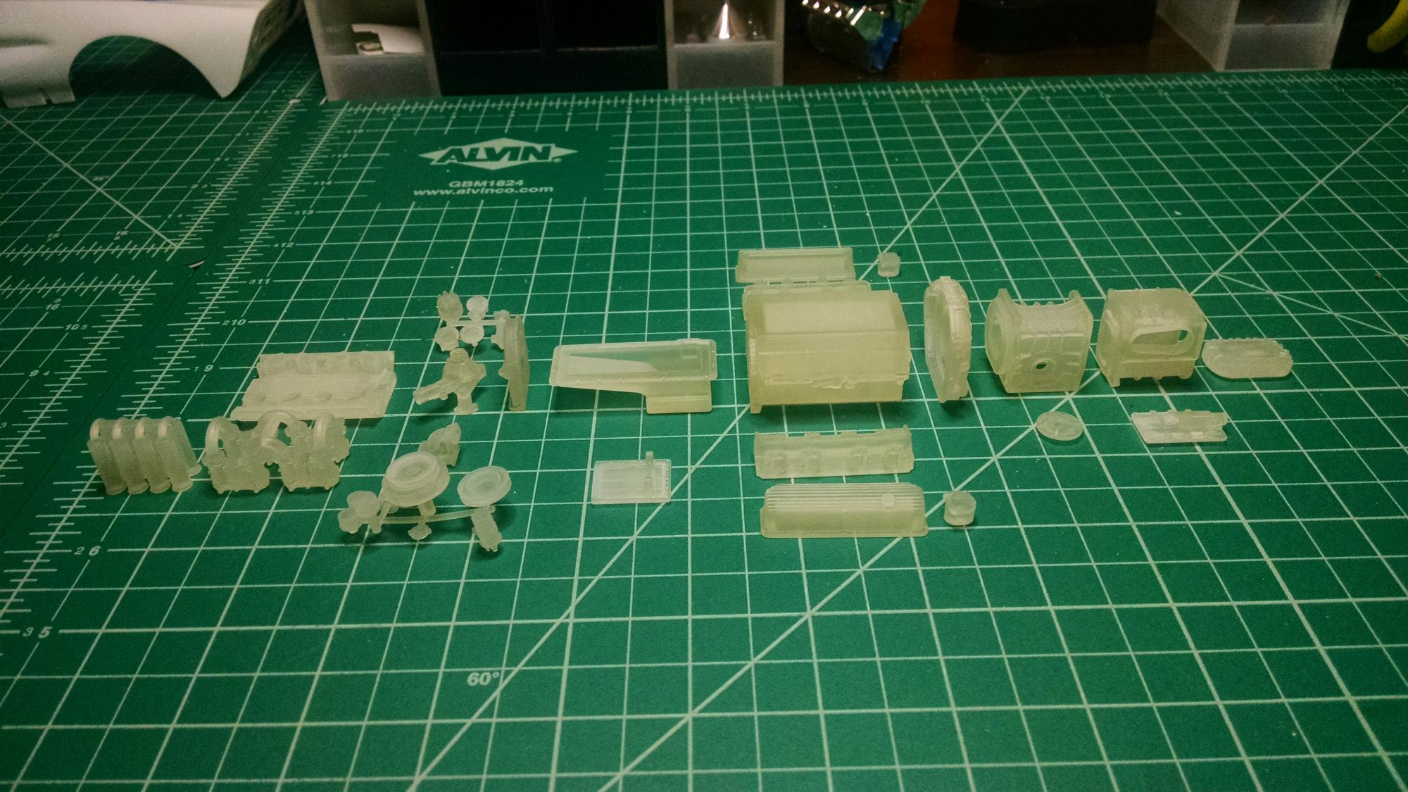
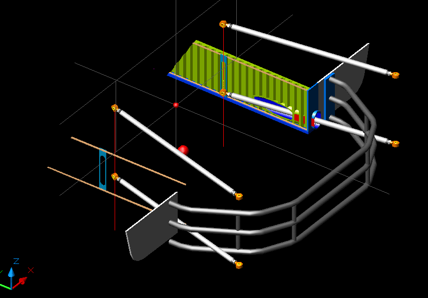
Last 3 pics. The engine in the pics is from TDR Innovations. The bundle of snakes exhaust that came with the Trumpeter kit wouldn't line up, so I had to design my own. Here's a snapshot of my design. I've got all the parts from the 3D printer and will post pics when I'm done in a few weekends.
-
Engine Intake for Trumpeter Ford GT40
StrangerBandFan replied to StrangerBandFan's topic in WIP: Model Cars
Just a few more, hope I'm not being selfish by hogging site memory capacity. mfm 9.pdf mfm 10.pdf mfm 11.pdf -
Engine Intake for Trumpeter Ford GT40
StrangerBandFan replied to StrangerBandFan's topic in WIP: Model Cars
A few more pics, not sure how many this site will let me post. mfm 6.pdf mfm 3.pdf mfm 5.pdf -
Engine Intake for Trumpeter Ford GT40
StrangerBandFan replied to StrangerBandFan's topic in WIP: Model Cars
Here's a few pics of the finished product. 3D printed parts: Throttle bodies, fuel rails and elbows, fuel injectors (3 pieces each), fuel line tee, fuel pressure regulator (2 pieces), electrical conduit, bellcrank. Homemade brass parts: Velocity stack plates, lower gaskets, fuel rail mounts, throttle cable holder, throttle spring clip, throttle position sensor bracket, idle adjustment and full throttle tabs, throttle linkage arms. All bolts, nuts, washers and throttle linkage rods are from RB Motion. Velocity stacks are from a guy in Belgium. Fuel injector wire is 5lb opaque black fishing line from Japan. mfm 1.pdf mfm 4.pdf -
Just finished one small part of my 1/12 Trumpeter Ford GT40 build. This is a custom intake for the engine. Lots of 3D printed parts, home made photoetched brass and purchased hardware. Here's a snapshot of the assembly I designed in AutoCAD. Pics of the finished assembly to follow today.
-
Tamiya 1/12 Ford GT40 with 3D Printing
StrangerBandFan replied to StrangerBandFan's topic in WIP: Model Cars
Got my rear shock towers and the rear plate that carries the engine cowl and tow hooks done. Next is the tube frame between the two with mounts for the header collectors, exhaust pipes and engine/tranny oil coolers. Got lots of parts coming from the 3D printers. Can't wait to see my fantasy turned into reality sitting in my hands!
-
Tamiya 1/12 Ford GT40 with 3D Printing
StrangerBandFan replied to StrangerBandFan's topic in WIP: Model Cars
Hi mad mike, I got a 403 code trying to use the link you show. I'd love to use that site as a reference if you've got a different link to it. -
Tamiya 1/12 Ford GT40 with 3D Printing
StrangerBandFan replied to StrangerBandFan's topic in WIP: Model Cars
Hi Davewilly, you and I are both old-school CAD, I started in '85 on Version 6, back when pen plotting on mylar was cutting edge stuff and you had to lick the pen tips when they clogged :-( and people who knew how to manipulate DOS were considered equal to rocket scientists! There's some great tutorials on YouTube that'll get you going with 3D if your interested. -
Tamiya 1/12 Ford GT40 with 3D Printing
StrangerBandFan replied to StrangerBandFan's topic in WIP: Model Cars
Hi mad mike, the engine is a 427 side oiler from TDR Innovations. It came with a wet sump pan, but I'm gonna make a dry sump and I've got the pump partially designed in one of the pics near the beginning of the thread. I used artistic license by switching to the quad webers :-) Thanks for the link you sent, I'll check it out and will follow your build closely too. Model on! -
Tamiya 1/12 Ford GT40 with 3D Printing
StrangerBandFan replied to StrangerBandFan's topic in WIP: Model Cars
Hi misterNNL, I was amazed the 3D printing was reasonably priced. All of the orange colored tubes in the image just above, plus the main roll bar assembly in the pics way above cost about 50$ including shipping. And that's using their most expensive high resolution printer and best resin plastic. I figure I'll have about $200 total when it's all said and done. -
Tamiya 1/12 Ford GT40 with 3D Printing
StrangerBandFan replied to StrangerBandFan's topic in WIP: Model Cars
Got a bunch more 3D design done over the holidays. Most of it is now colored as I'll paint it. The turquoise is my interpretation of the blue they used on the 1966 race cars, and of course, Gulf orange tubing to match the stripes on the car. Sent a bunch of it to the printers, so I'll have pics of an actual assembly in a couple weeks! I felt I'm missing something in model building doing all of this 3D stuff, so I spent several days making wheel tubs from styrene sheet. Pics to come in next post. Building by hand is very satisfying.
-
Tamiya 1/12 Ford GT40 with 3D Printing
StrangerBandFan replied to StrangerBandFan's topic in WIP: Model Cars
Hi Mooneyzs, I use 2D AutoCAD in my business, but learned 3D back in the late 90's. Looking forward to check out some of your builds! -
3D Printed Part Smoothing Breakthrough
StrangerBandFan posted a topic in Tips, Tricks, and Tutorials
I just started using 3D printed parts in my builds and faced the challenge of getting rid of the layering lines. I use Shapeway to print my parts. They have a large variety of materials to choose from and each has it's own unique characteristic. For highly detailed parts, I always use their Frosted Extreme Detail (FED) materials because they use a printer that has 16 micron thick layers, pretty much the highest resolution you can get. The minute layer ridges still show up, especially on things like 1/12 scale Weber carbs, and painting just exaggerates them. Check out my post in On The Workbench of my 1/12 Ford GT40 build for some pics of parts I've had printed. The post is titled as Tamiya, but it's a Trumpeter model. My goof! All of those pics show parts that haven't been smoothed yet. The web is full of ideas on how to smooth the layer ridges off these parts. Sanding, epoxy washes, acetone and ethyl acetate vapor chambers and air erasers. I tried them all with limited or no success. The air eraser idea gave me an idea. I bought an ultrasonic jewelry cleaner, partially filled it with baking soda, put some test parts in and ran it through four 480 second cycles (the max the cleaner will run). What a huge difference! then I used an electric toothbrush (no, not the one I use on my teeth :-) ) and some Tamiya red cap course polishing compound and ran it all over the parts for a couple cycles of the brush and they came out as smooth as a baby's bottom without losing any of the fine detail of the parts! Success at last. Word of warning, the ultrasonic cleaner relies on being filled with liquid to cool the electronics inside it. When using baking soda, it gets VERY hot unless you let it rest for a few minutes between cycles. Use with caution, I'm not responsible if you burn your house down. Now I put the cleaner in the frig for 30 minutes before I start and wait 10 minutes between cycles and it barely gets warm to the touch. I've got a second cleaner full of water and TSP (tri-sodium phosphate, a common cleaning agent found in the paint section of any hardware store) to clean off the baking soda and polishing compound. I just started this process, and want to post pics of a set of parts all the way from rough from the printer to final paint. I'm only part way done and will post them soon. I was so excited figuring this out I thought I'd share the basic info now in case anyone else wants to try it. Please post your results and any other ideas you have. -
Tamiya 1/12 Ford GT40 with 3D Printing
StrangerBandFan replied to StrangerBandFan's topic in WIP: Model Cars
Thanks, geetee66, Funkychicken and superbike-shaun for your encouraging comments and direction to the sizing chart! Glad I'm inspiring people. Even though most people don't have AutoCad 3D at home like me, there's a TON of stuff out there you can buy, although pretty pricy. Got my engine in last weekend. Ford 427 side-oiler with quad Weber carbs and ZF transaxle. Bought from TDR Innovations, he sells his stuff through Shapeway but has his own site for viewing and has a bunch of cool stuff, very detailed and accurate down to the mounting bosses for the engine mounts! Tim is a great guy to work with, willing to go the extra mile to get you the correct size parts you need. I've got it temp glued with white Elmers for test fitting in the chassis. The 3D computer snaps look like a fantasy until you get the parts in hand :-) More food for thought, I draw on the computer, print it on paper, cut it out and tape it on the actual model like in the pics below to make sure things fit before printing in 3D. Gives me a good idea if things are the correct scale too. More to come soon, I've got more parts in process at the printers.
-
Tamiya 1/12 Ford GT40 with 3D Printing
StrangerBandFan replied to StrangerBandFan's topic in WIP: Model Cars
Getting some work done on the rear suspension. All rod linkage will be from RB Motion. Everything else will be 3D printed. The tunnel through the honeycomb beam is perfectly tapered to the arc of the trailing rod. Had to walk away from the computer a few times out of frustration before I finally got it right! Hope everyone has a great holiday season.