RCprofile.JPG.6b95b19b856bf00a3becd6aeaaa48f3b.JPG)
Ian McLaren
-
Posts
1,112 -
Joined
-
Last visited
Content Type
Profiles
Forums
Events
Gallery
Everything posted by Ian McLaren
-
RCprofile.thumb.JPG.1691ea753d0f0897fdc1b2510cf06775.JPG)
full detail 1/16th Gordie Bonin BubbleUp Trans Am Funnycar
Ian McLaren replied to Ian McLaren's topic in WIP: Drag Racing Models
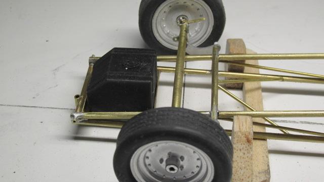
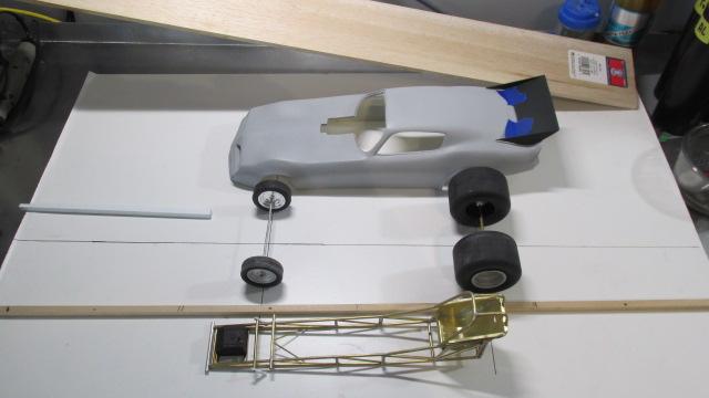
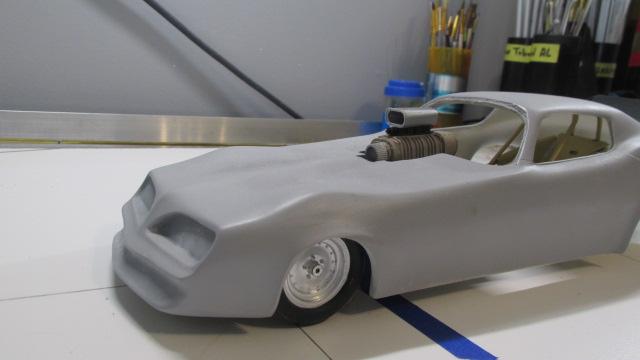
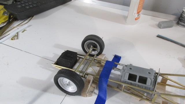
A milestone dayThe first time the body has been fitted over the chassis, and the first time that the chassis is supported by both its front and rear axles as a roller. Tonight we drink!
- 52 replies
-
- 1
-

-
- scratch built
- brass chassis
- (and 1 more)
-
full detail 1/16th Gordie Bonin BubbleUp Trans Am Funnycar
Ian McLaren replied to Ian McLaren's topic in WIP: Drag Racing Models
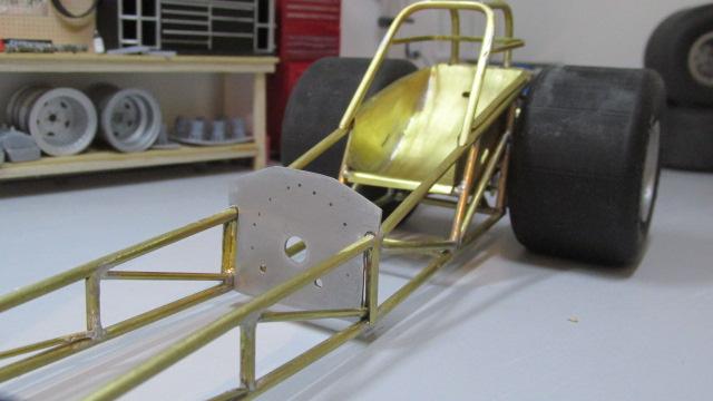
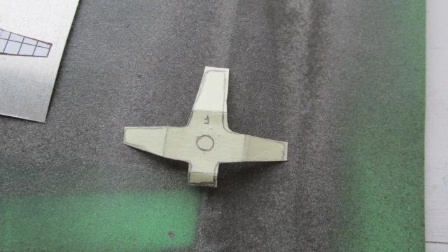
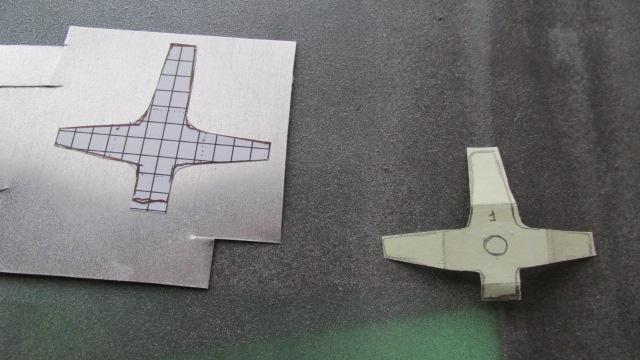
Fuel tank hold down bracket now added, also added image of the original rough template, corrected template on graph paper and cut out aluminum part before final shaping and polishing
- 52 replies
-
- 1
-
-
- scratch built
- brass chassis
- (and 1 more)
-
full detail 1/16th Gordie Bonin BubbleUp Trans Am Funnycar
Ian McLaren replied to Ian McLaren's topic in WIP: Drag Racing Models
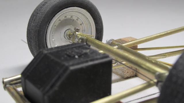
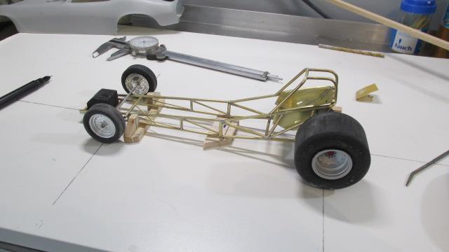
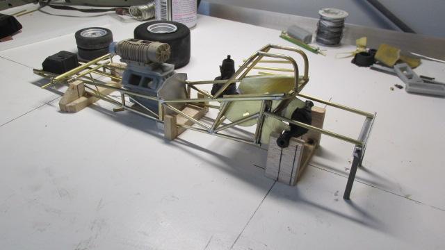
Front suspension is just about done, just need to build the front radius rods and finish cleaning up the axle. Looks like the front torsion bar will be functional once I set the ride height.
- 52 replies
-
- 2
-
-
- scratch built
- brass chassis
- (and 1 more)
-
full detail 1/16th Gordie Bonin BubbleUp Trans Am Funnycar
Ian McLaren replied to Ian McLaren's topic in WIP: Drag Racing Models
Thank you very much Francis for the feedback! You are correct the jig does take some time to create (read several hours) but at the end of the project the savings will be measured in days. It makes almost everthing from here on much easier. Not only does it allow me to check for square, flat and twisted but it provides a secured chassis to attach to and work from. In the real world the rear end is attached to the jig and every tube is referenced off that. In a model that isn't practical so a partially built chassis helps construct the jig. Critical measurements on the jig are made and placed independant of the chassis though and then the chassis is checked against those to see if it is correct (it wasn't) and then corrected (it was). At this stage the corrections were rather easy but as additional bars and tubes are added the chassis becomes much stiffer and harder to manipulate. I highly recommend anyone building a tube chassis car even if your using a kit chassis make at least a simple jig, it will, I promiss make the build easier, better, and I think, more fun.- 52 replies
-
- 1
-
-
- scratch built
- brass chassis
- (and 1 more)
-
I have been following this project kind of on a hit and miss basis as I mostly hang out on the drag race pages. I did however go back are read all 15 pages of this increadible display of talent, machining and just all around craftsmanship. The insights on dealing with brass and other metals will prove invaluable to my modeling. Not to mention the subject matter is a testament to racecar engineering and is fasinating in real life (Laguna Seca) but in this scale ------- no words.
-
full detail 1/16th Gordie Bonin BubbleUp Trans Am Funnycar
Ian McLaren replied to Ian McLaren's topic in WIP: Drag Racing Models
Thanks for the comment Daniel, yes an adjustable jig would be a great thing. Sadly the closest I have gotten is to be able to use a couple of parts from previous jigs. Doing a chassis like this comes with the same issues as building a real one all be it on a different scale, and forces you to solve the issue in the same way. Call me delusional but I feel the process somehow adds a dimension of authenticity to the finished product or at least in my world. LOL- 52 replies
-
- 1
-
-
- scratch built
- brass chassis
- (and 1 more)
-
full detail 1/16th Gordie Bonin BubbleUp Trans Am Funnycar
Ian McLaren replied to Ian McLaren's topic in WIP: Drag Racing Models
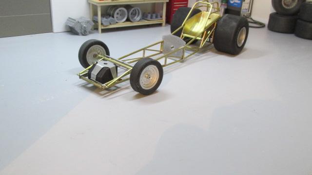
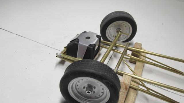
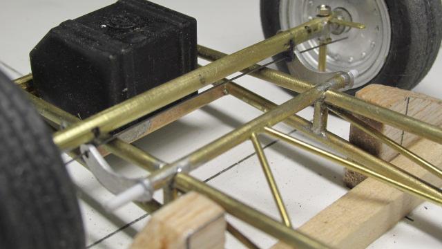
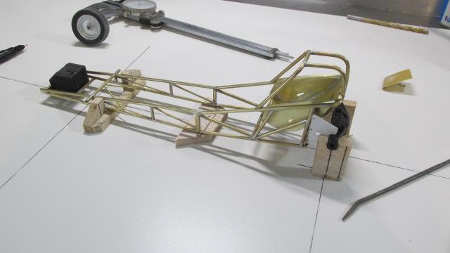
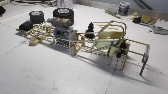
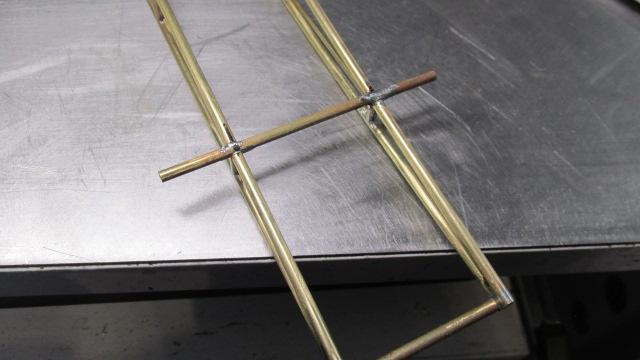
Small update, the chassis is located in the jig I made to make sure everything stays aligned. The chassis is located by the differential in the rear and a removable 3/32 pin in the front. As well as assuring the chassis is square, level and not twisted, the jig also sets the ride height, providing a reference for the body and its front and rear support structures, headers, and wheelie bars. It will also act as a secure structure for adding the tin to the body and chassis without having to install the wheels and tires to check the clearances. Also the front straight axle and spindles are built but still need brackets for the torsion bar arms and also front radius rods. Below are photos showing details of the chassis jig construction. first photo is the centerlines of the jig and front and rear axles as well as materials used, second photo it the differential housing mounted level and square and at the correct ride height for the rear tires. This has to be accurate as almost everything stems from this piece and these two lines.
- 52 replies
-
- 4
-
-
- scratch built
- brass chassis
- (and 1 more)
-
full detail 1/16th Gordie Bonin BubbleUp Trans Am Funnycar
Ian McLaren replied to Ian McLaren's topic in WIP: Drag Racing Models
Thanks Tim, this seat went quicker than the last one, I guess I'm making some progress on this brass deal. -
full detail 1/16th Gordie Bonin BubbleUp Trans Am Funnycar
Ian McLaren replied to Ian McLaren's topic in WIP: Drag Racing Models
Well another day with at least some progress. The straight axle and spindels are built but not cleaned up yet and the front rotors were printed and modified to fit.
- 52 replies
-
- 3
-
-
- scratch built
- brass chassis
- (and 1 more)
-
full detail 1/16th Gordie Bonin BubbleUp Trans Am Funnycar
Ian McLaren replied to Ian McLaren's topic in WIP: Drag Racing Models
Tony and Randy thank you for the kind words, this Swindahl style chassis has really been a learning experience for me as everything has had to be sized strictly from photos, lots of measuring and comparing of pictures involved. I will probably post the scale drawing once I'm as close as I can get to correct and I know everything fits properly in case someome else wants to try one of these. Perhaps one of the Corvette bodied cars Al built. -
full detail 1/16th Gordie Bonin BubbleUp Trans Am Funnycar
Ian McLaren replied to Ian McLaren's topic in WIP: Drag Racing Models
Thank you so much John, I'm not sure there is much extraordinary in this particular model but perhaps a tip or two along the way. -
full detail 1/16th Gordie Bonin BubbleUp Trans Am Funnycar
Ian McLaren replied to Ian McLaren's topic in WIP: Drag Racing Models
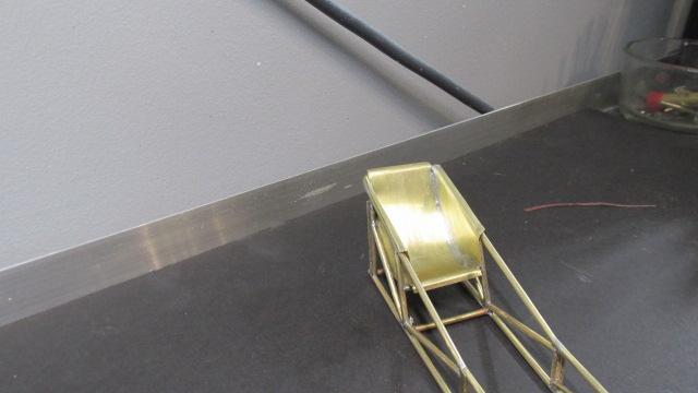
More progress, rear seat support bars and seat belt bars added, seat is built but not fully detailed, needs weld beads and fasteners added. also spent some time on the reverser ( built a handle and detail painted the housing) also have to add the front drive shaft coupler and retaining ringI'm also including some photos on the seat building process from template to fully soldered. Below are the photos of the seat builing process,and Templates used. ALso it shows the assembly order and the use of iron wire to secure the seat and back panel to the chassis to be sure of a proper fit (also solder does not stick well to iron).
- 52 replies
-
- 1
-
-
- scratch built
- brass chassis
- (and 1 more)
-
full detail 1/16th Gordie Bonin BubbleUp Trans Am Funnycar
Ian McLaren replied to Ian McLaren's topic in WIP: Drag Racing Models
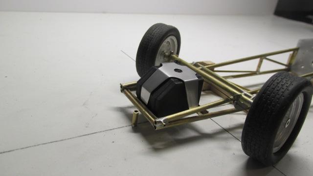
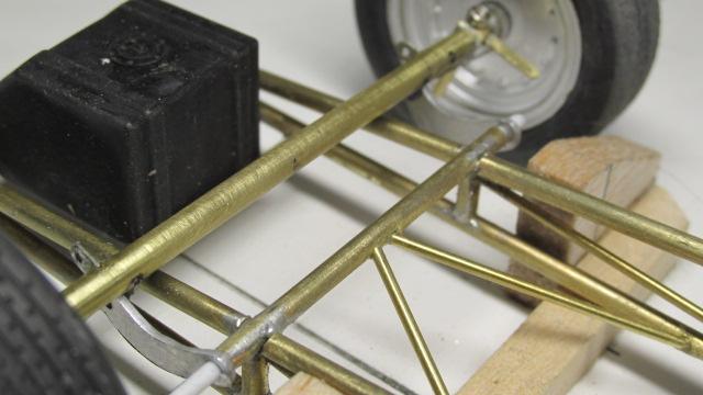
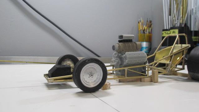
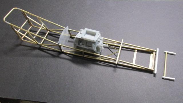
Better day today as far as progress goes, a couple of additional bars in (seat support), motor plate roughed out and fitted to the chassis (needs some holes drilled). Removeable weight bar in position, can be removed for painting the chassis and the test, functional torsion bar, is sitting in front of the chassis. It works quite well but setting the initial ride height may prove challenging
- 52 replies
-
- 2
-
-
- scratch built
- brass chassis
- (and 1 more)
-
’72 Dodge Demon Drag Racer 1/25 scale
Ian McLaren replied to AmericanMuscleFan's topic in WIP: Drag Racing Models
You just keep raising the bar Francis, I love it! -
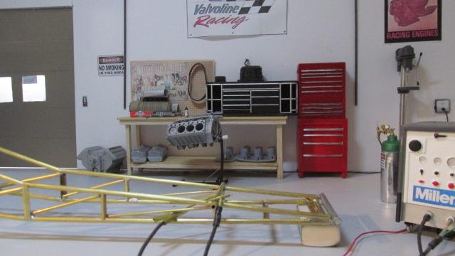
Up graded bench area, and new Swindahl style chassis in the shop.
-
full detail 1/16th Gordie Bonin BubbleUp Trans Am Funnycar
Ian McLaren replied to Ian McLaren's topic in WIP: Drag Racing Models
Torsion bar housing and braces added and axle location shown Notches cut in upper rail (trickiest part) also note small bracing tubes running from the lower rails to the center of the torsion bar housing. Housing will be narrowed when the torsion bar itself is inserted Axle sit above the entire frame and in front of the torsion bar, I am currently fabrication the straight axle and mounting arms from the torsion bar as well as spindles and king pins
- 52 replies
-
- 3
-
-
- scratch built
- brass chassis
- (and 1 more)
-
full detail 1/16th Gordie Bonin BubbleUp Trans Am Funnycar
Ian McLaren replied to Ian McLaren's topic in WIP: Drag Racing Models
Daniel your brass work is incredible, it's you I'm trying to keep up with. I can't wait for you to bring the Surfers chassis back out so I can pick your brain some more.- 52 replies
-
- 1
-
-
- scratch built
- brass chassis
- (and 1 more)
-
full detail 1/16th Gordie Bonin BubbleUp Trans Am Funnycar
Ian McLaren replied to Ian McLaren's topic in WIP: Drag Racing Models
Firstly, thank you Francis it does work fairly well. When I read your question it struck me as slightly odd and then I realized that it was a great question to which I didn't have an immeadiate answer. When we had the fab shop, chassis were built with tube, with the only questions being 4130 or mild steel and what size. I have always used tube for the vast majority of my chassis, but your question made me really think it through. Rod would seem to have advantages, more surface area in the joints for better adhesion, bends could be made with out crushing, less likely to bend, so why not use it. Tubing also has advantages, the open ends look right, butt joints with an internal sleeve are much stronger than any flush butt joint, it's much easier to drill a hole into the center cavity for a pin joint and perhaps the biggest one is that tubes are much easier to fishmouth than a rod, making fabrication some what quicker. Price wise the difference is very small and availability is usually good for both. So the question remains why use tube instead if rods for a chassis? Cause that's what their made of I guess. LOL- 52 replies
-
- 2
-
-
- scratch built
- brass chassis
- (and 1 more)
-
full detail 1/16th Gordie Bonin BubbleUp Trans Am Funnycar
Ian McLaren replied to Ian McLaren's topic in WIP: Drag Racing Models
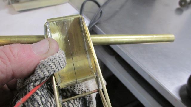
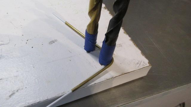
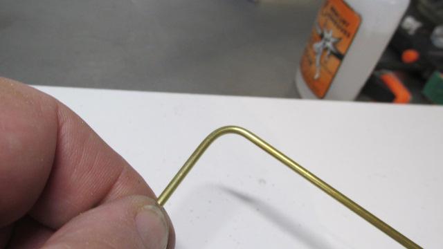
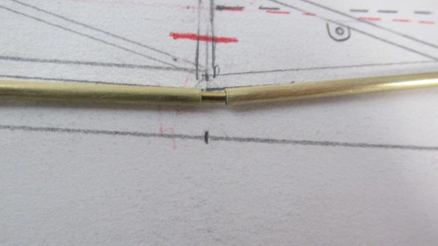
Base chassis assembled, and some photos of how it was supported to soldered. Also I posted the photos of how I made the bends in the rear upper bar using 3/32" brass tubing ,.060 white styrene rod stuffed in the tube and three drill bits to form the radius. The tape was used to adjust the size accros the chassis and also to protect the brass tube from damage. Simple and will work on most sizes of tube and a reasonable radius (not too tight)
- 52 replies
-
- 4
-
-
- scratch built
- brass chassis
- (and 1 more)
-
full detail 1/16th Gordie Bonin BubbleUp Trans Am Funnycar
Ian McLaren replied to Ian McLaren's topic in WIP: Drag Racing Models
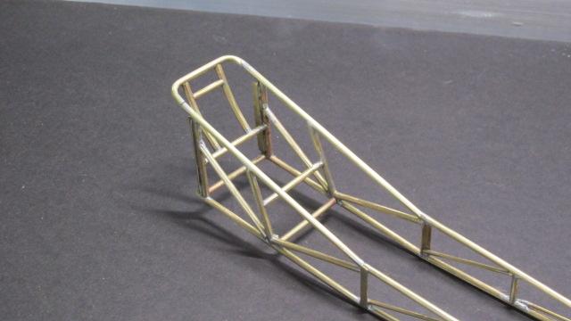
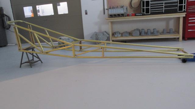
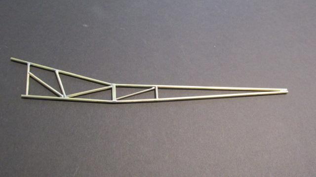
Further progress on the Swindahl style chassis, all major bars now in place, should be able tp assemble the basic chassis shortly
- 52 replies
-
- 3
-
-
- scratch built
- brass chassis
- (and 1 more)
-
full detail 1/16th Gordie Bonin BubbleUp Trans Am Funnycar
Ian McLaren replied to Ian McLaren's topic in WIP: Drag Racing Models
Chassis is moving from drawing to the assembly jig, construction now under way.
- 52 replies
-
- 1
-
-
- scratch built
- brass chassis
- (and 1 more)
-
’72 Dodge Demon Drag Racer 1/25 scale
Ian McLaren replied to AmericanMuscleFan's topic in WIP: Drag Racing Models
If it wasn't for the dime in some of the photos, this would simply be an article in Hot Rod Magazine about someone building a real car. The fidelity to scale is off the charts. Amazing! -
full detail 1/16th Gordie Bonin BubbleUp Trans Am Funnycar
Ian McLaren replied to Ian McLaren's topic in WIP: Drag Racing Models
I'm glad you like it Francis, I kind of thought this one might be in your wheel house, even though is has no doors. I too like the era when you could tell what kind of car it was without having to look a the painted on grill and tail lamps. I'm also going to put in more tips and tutorials on how I have done things, as there is still going to be quite a bit of scratch building on this one.- 52 replies
-
- 1
-
-
- scratch built
- brass chassis
- (and 1 more)
-
full detail 1/16th Gordie Bonin BubbleUp Trans Am Funnycar
Ian McLaren replied to Ian McLaren's topic in WIP: Drag Racing Models
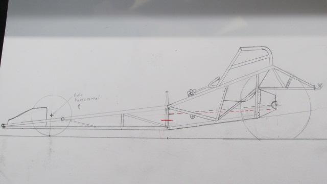
Thank you John, Here is a bit of an insight to what is going on. This is my drawing of the Swindahl chassis that this car used, I'm still doing research on it but I'm pretty sure the bulk of it is fairly accurate. The tapered chassis and front suspension were quite different from the norm. Someone may have already modeled this chassis at some time but I;m not aware of and I'm almost positive it has never been offered in kit form.
- 52 replies
-
- 2
-
-
- scratch built
- brass chassis
- (and 1 more)
-
full detail 1/16th Gordie Bonin BubbleUp Trans Am Funnycar
Ian McLaren replied to Ian McLaren's topic in WIP: Drag Racing Models
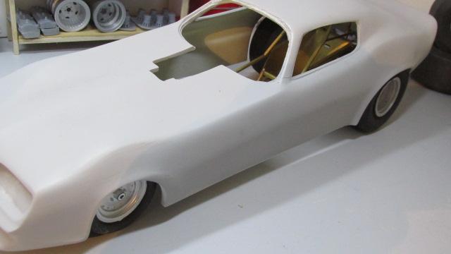
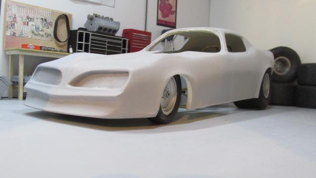
Although I just officially started this post yesterday, I have been chipping away at the body around finishing a 1/25 Beretta Promod for a friend. The first photo is of the Flashpoint T/A body before the changes started next to a 1/25th Comp Resins body that wasn't much closer. The modifications done to this point are, remove the front ProMod style air dam and replace it with a more stock style front spoiler that is also much narrower, the front fenders ahead of the wheel wells were also narrowed and also tucked under to visually narrow the nose of the car. The side window openings have also been modified to be closer to the real car. the blower hole in the hood area has been roughly extended as the motor will sit out further forward than was allowed for in the body, and the hood profile in that area was flattened as well. Blisters were also added above the front wheels to allow for a reduce ride height and also to provide move clearance at speed when the front of the body presses down due to the airflow (this was actually the primary reason the were installed on the cars back then). The front wheel openings were move foward and up to better match the real cars 125 inch wheel base ( the Flashpoint body was built to fit the Revell chassis which measure 120 inch between the wheels). Finally I trimmed the body sides of the car starting with1/16th inch shorter at the front wheel wells to 5/16th at the rear wheel wells to back date the look of the original body. The body now looks much better but I am probably going to have to trim a little more for the correct look, but that will have to wait till the body can be set on the chassis at the correct ride height
- 52 replies
-
- 5
-
-
- scratch built
- brass chassis
- (and 1 more)