

Pg265
-
Posts
118 -
Joined
-
Last visited
Content Type
Profiles
Forums
Events
Gallery
Posts posted by Pg265
-
-
Good evening,
As usual, a lot of research work, preparation/modification and assembly.
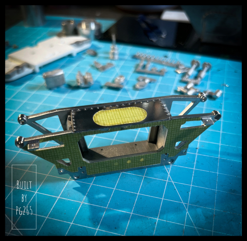
The front of the chassis is assembled, its photo-etched upper part is drilled, installed and riveted.
Everything is masked for the painting phases.

The upper suspension arms made up of 4 parts are assembled by welding: it's stronger and more fun.
They are drilled and tapped to receive 1.4x3 screws.
The majority of parts intended for the front axle are awaiting the primer coat…
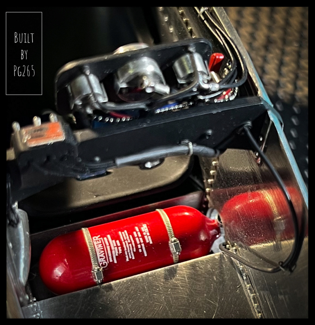
...with which they are now adorned.The fire extinguisher was painted and varnished yesterday and received its decal this morning: Classic chronology!
However, in my opinion, details were lacking; I tweaked 2-3 things.
I turned the tip and a small gauge then assembled them.
The Mano is 2.4mm with a small shoulder of 1/10th to center and give a little depth to the dial.
Serflexs are added, equipped with cruciform screws.
The decal is deliberately placed forward (as if the cylinder was turned), and the Serflex slightly offset to give a little dynamism.
Of course, you can't see much once everything is installed, but it's there and it was fun to make!
The fire extinguisher handle cable is held using a small photo-etched Top Studio part.
The shock absorbers are assembled and decorated.
The previously prepared parts, painted varnished... allowed the front train to progress.
The whole thing is riveted where it seems necessary.
The pedal assembly is installed and the accelerator pedal is equipped with its control for the cable (clevis, nut, bolt, washers.)
Let’s go to the lathe for the discs and hubs.
They are equipped with their spindles and installed on their hub carrier. The calipers are temporarily positioned, awaiting bleeding and fittings for the braided brake fluid lines.
More soon.
Pascal.
-
Good evening,
Here is some progress again, still in the cabin.
Sewing workshop today!
The fabric straps provided in the kit went into the cabinet box. New ones, made of lead sheet, are primed, painted, “sewn” and partly installed.
A few oils will finish the job.
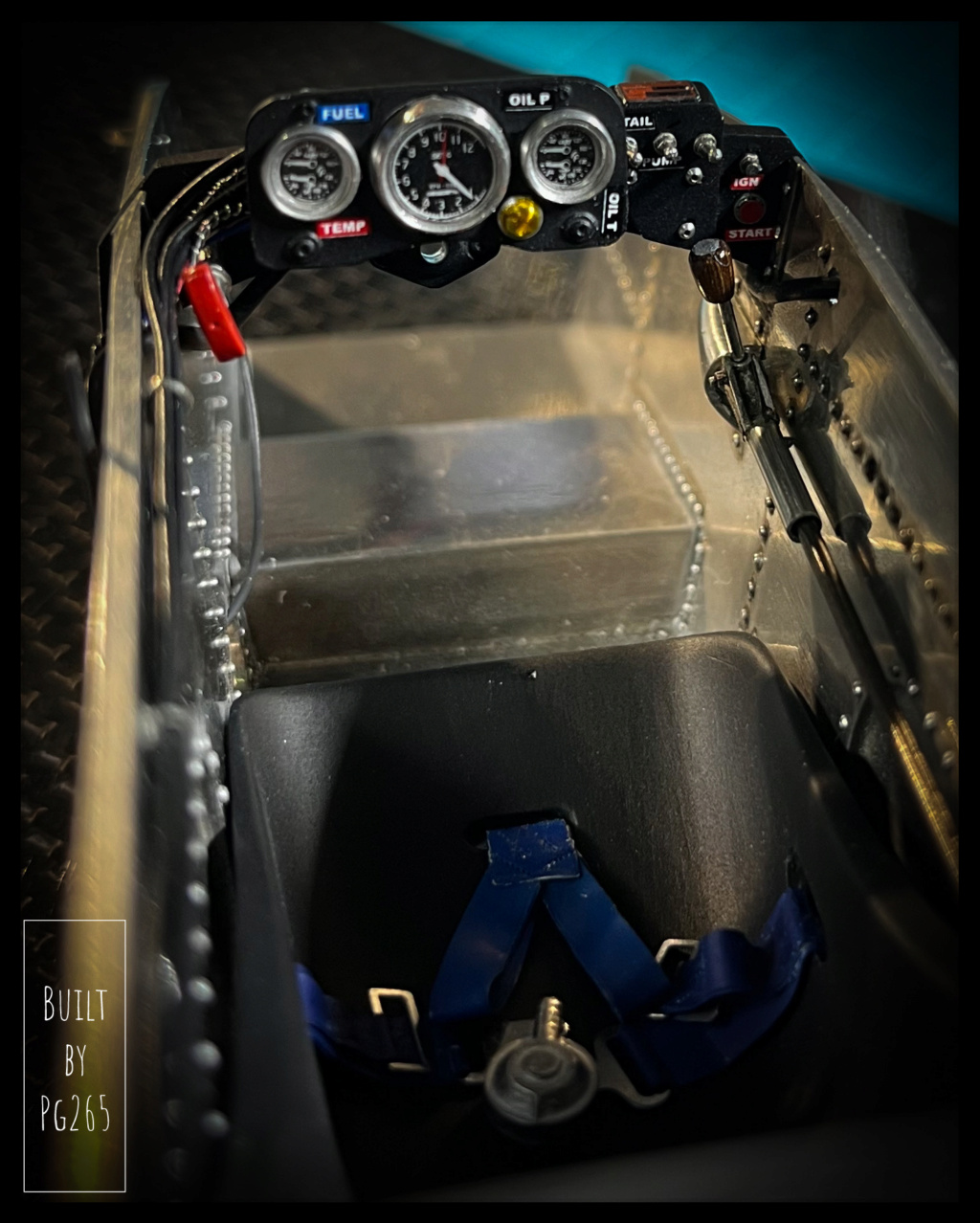
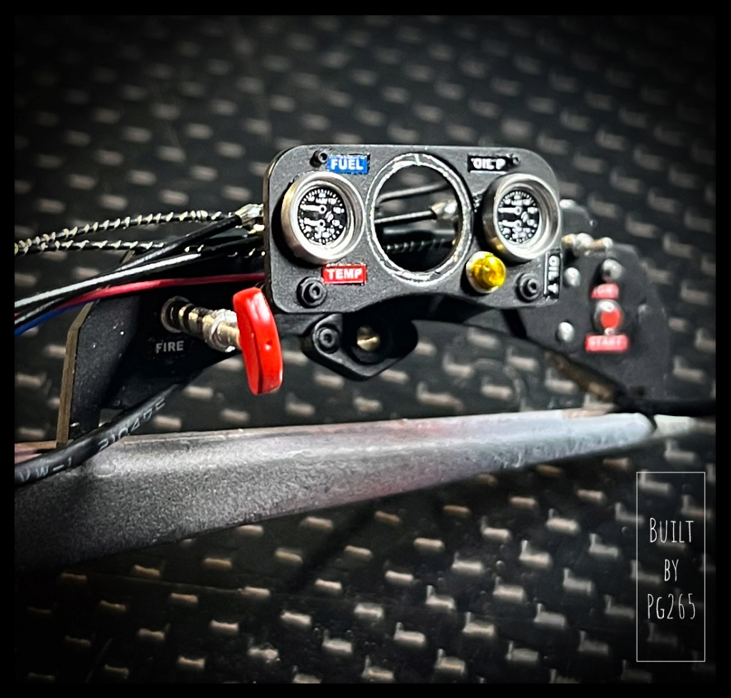
The dashboard is completed and put in place.
The fire extinguisher bottle is the next step: need to paint it and turn a part to make it a little better and connect the pull cable to it.
More soon.
Pascal
-
Good evening,
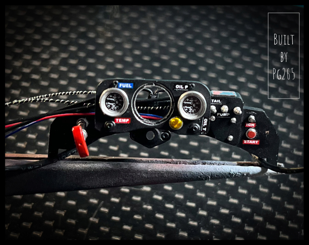
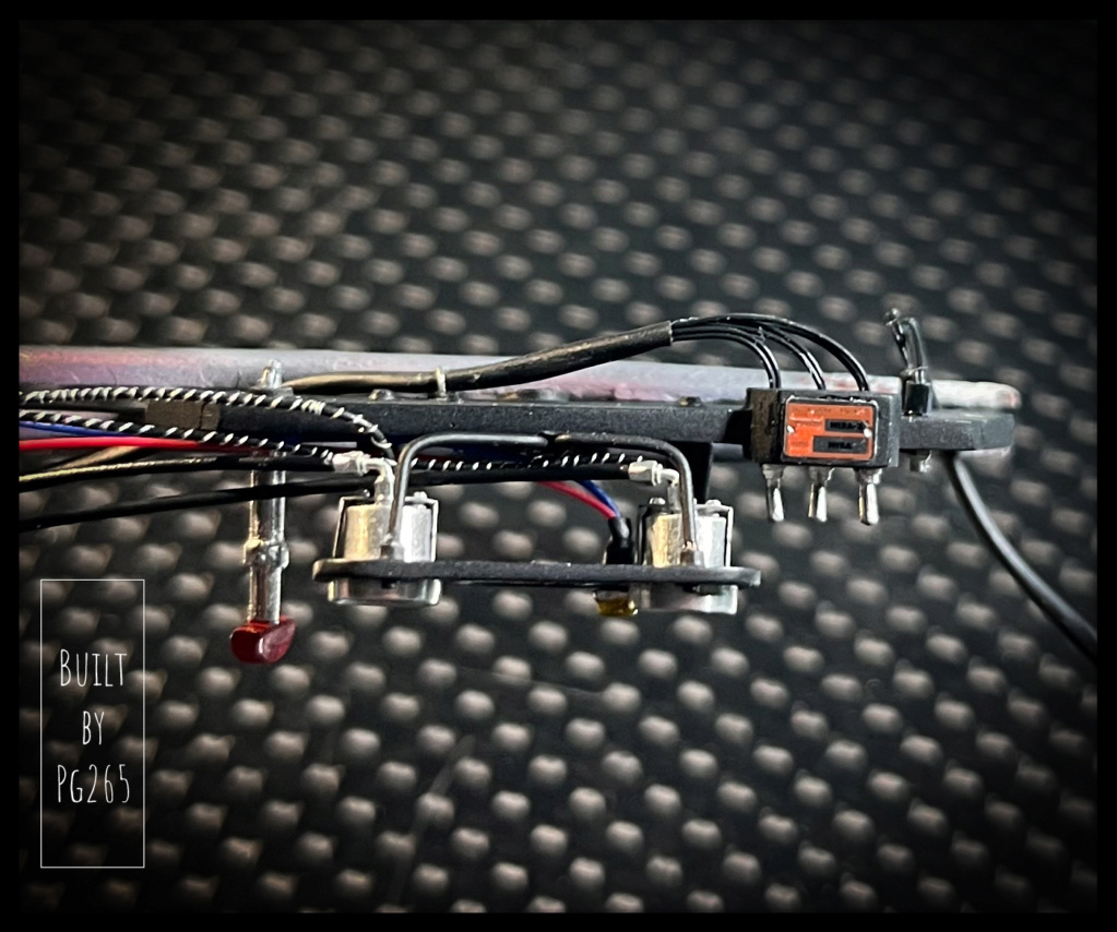
Work on the interior continues, particularly on the dashboard.
I started from the principle that, although pretty, it was possible to add 2 or 3 details.
Some modifications are made to the pressure gauges (pressure connections, specific cable for temperatures) the starter push button is turned, the switches and other indicator lights connected, the support for the small panel created...
The rev counter is on stand-by: the needles must be painted.
The glasses will finalize the assembly of the meters.
It's progressing slowly, but it's moving forward.
Pascal
-
 1
1
-
-
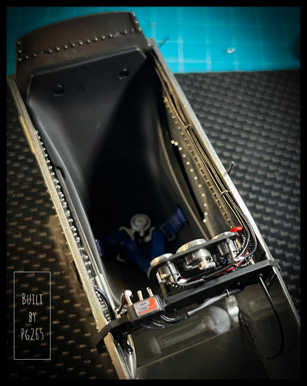
Good evening,
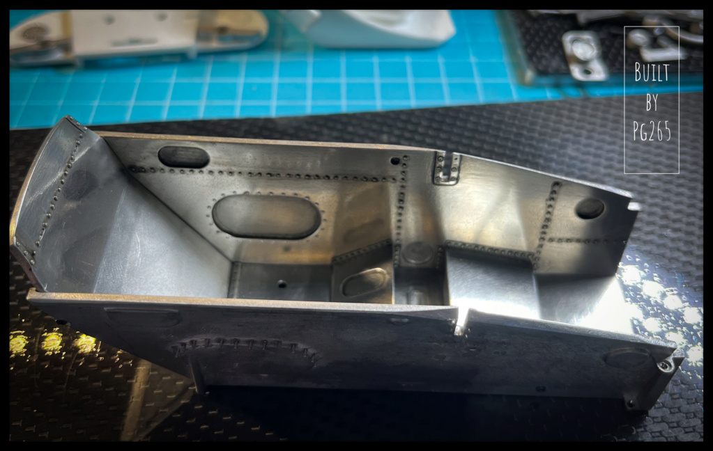
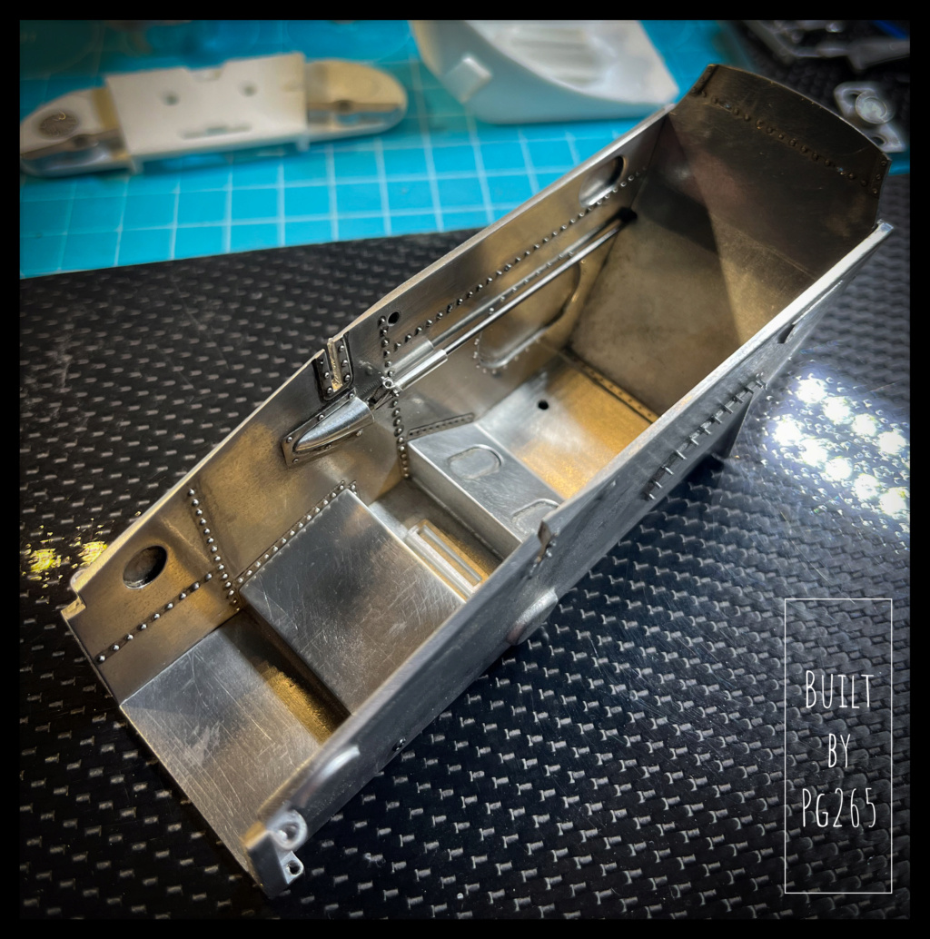
The “bathtub” is:
- Polished,
- riveted,
- assembled (welded)
The gearbox control linkage has been modified: the White Metal part is cut and replaced by a blued brass one.
The selector is detailed with the addition of welds, a bolt accompanied by its nut and washers.
It’s more coherent, pretty… and I like it!
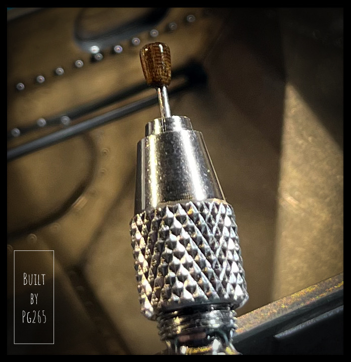
The original knob is very good.
I told myself that rather than painting it in wood tones, I would make one… in wood.
I cut a “cube” from a piece given to me by a friend (stratospheric model maker!!), of a species that I don’t remember.
I then simply turned it and varnished it.
This type of wood is very hard, but very beautiful.
Not much image today (Las Vegas this morning, flight this afternoon), but work and lots of preparation and modifications which should quickly make progress in the cockpit.
Besides, since I like simplicity and think of everything…
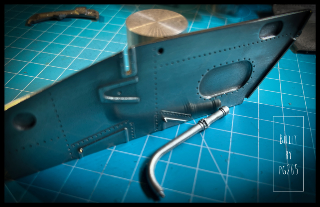
I decided to drill the left side of the bathtub.
This is of course the thickest part, for a large diameter hole... with all my rivets next to it.
It was necessary to take out different diameters of drills and finish with the step drill.
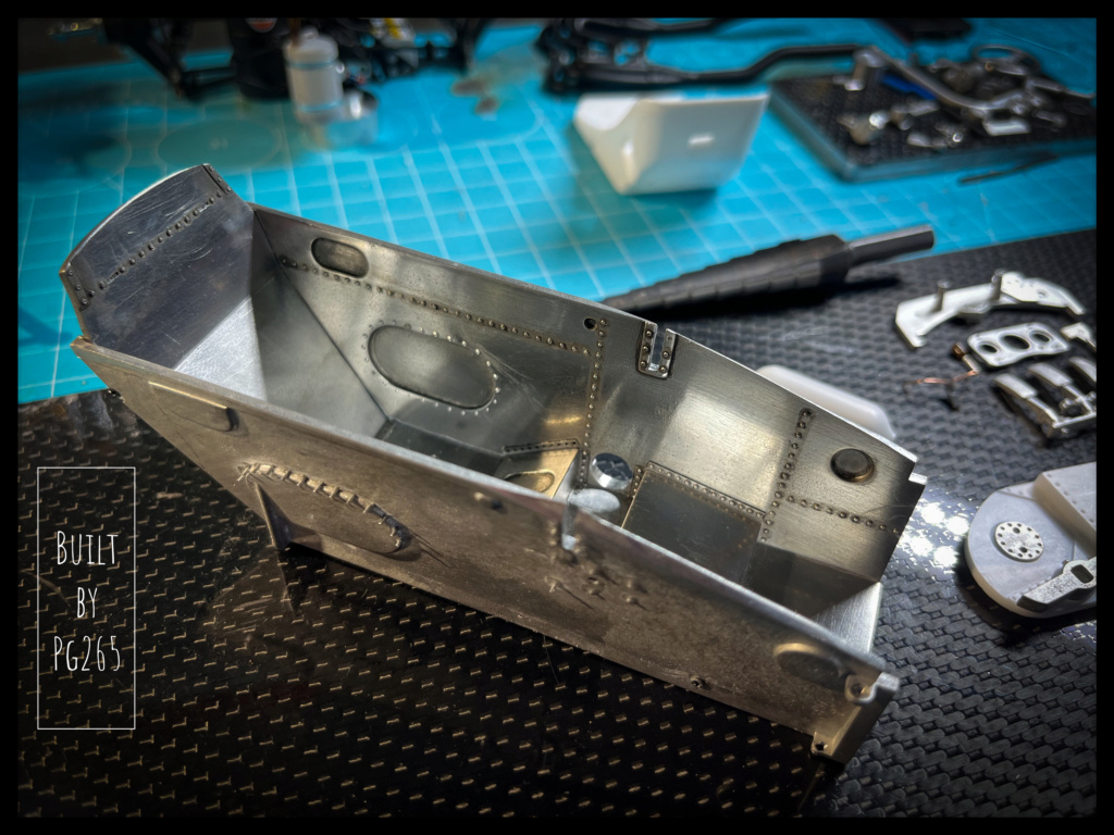
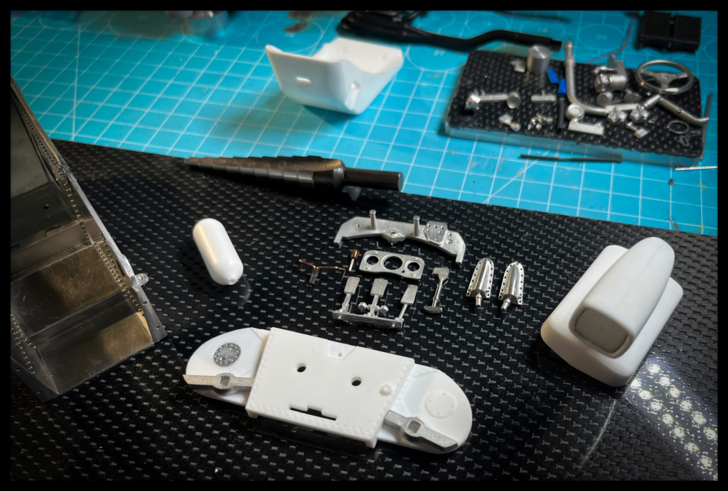
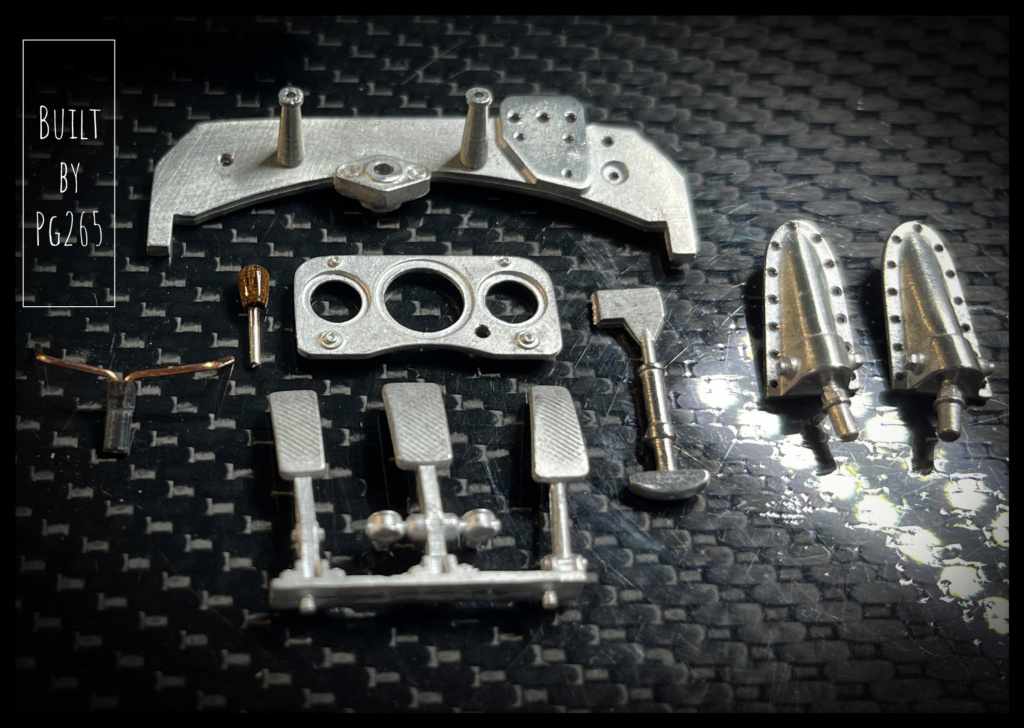
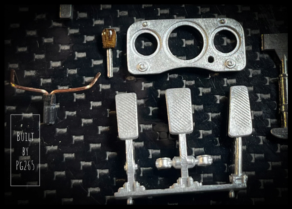
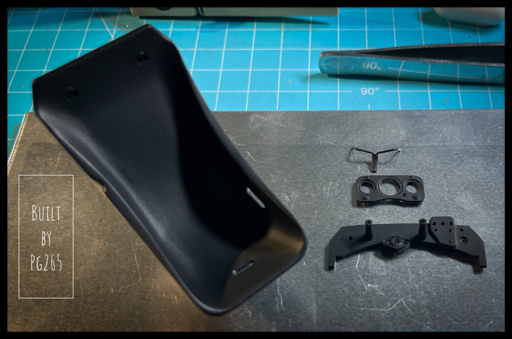
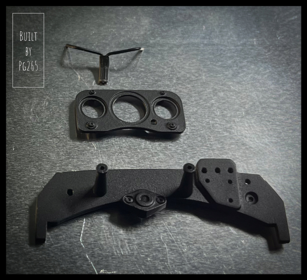
Here is some of the prepared pieces.
I reproduced the appearance of the anti-slip engraving on the pedals; for what we will see… but it’s there!
And here is some of the painted pieces waiting for all their details.
That's it that's all.
Pascal -
Good evening,
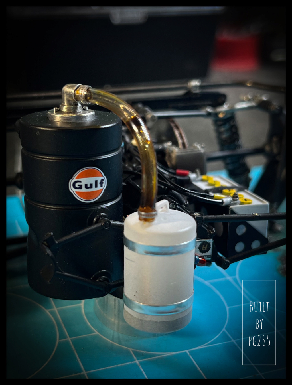
The can straps are done, the Serflex in place and a Gulf sticker brightens up the oil tank.
I drilled a hole in the axis of the cap and slipped a little “oil” in for more consistency: it comes from the top, flows down the side of the can to the bottom.
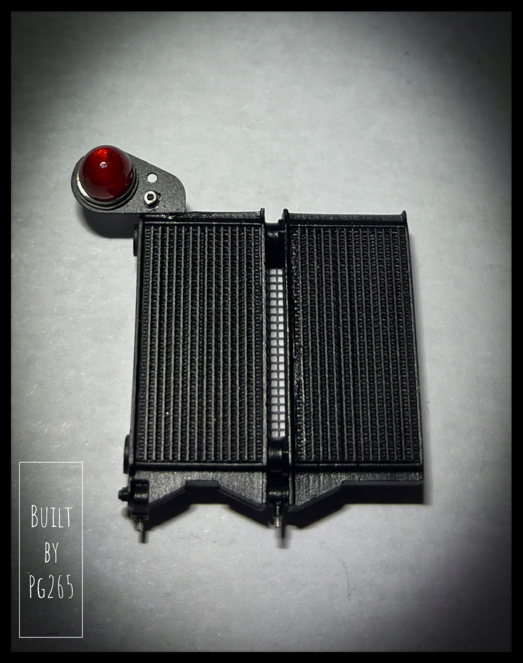
A terminal, screws and cable: the rear light is ready to be connected.
Time to take care of the interior.
The first step is to start giving a little shine before riveting the aluminum sheets.
More soon.
Pascal -
Good evening,
Thank you for your comments.
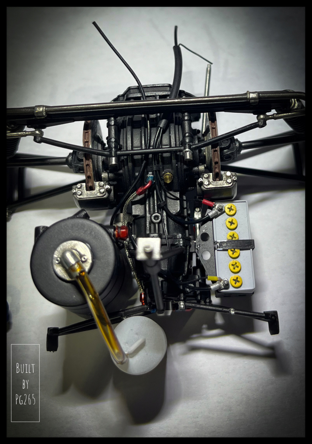
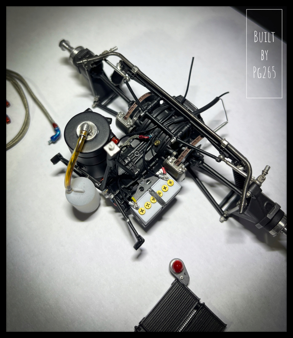
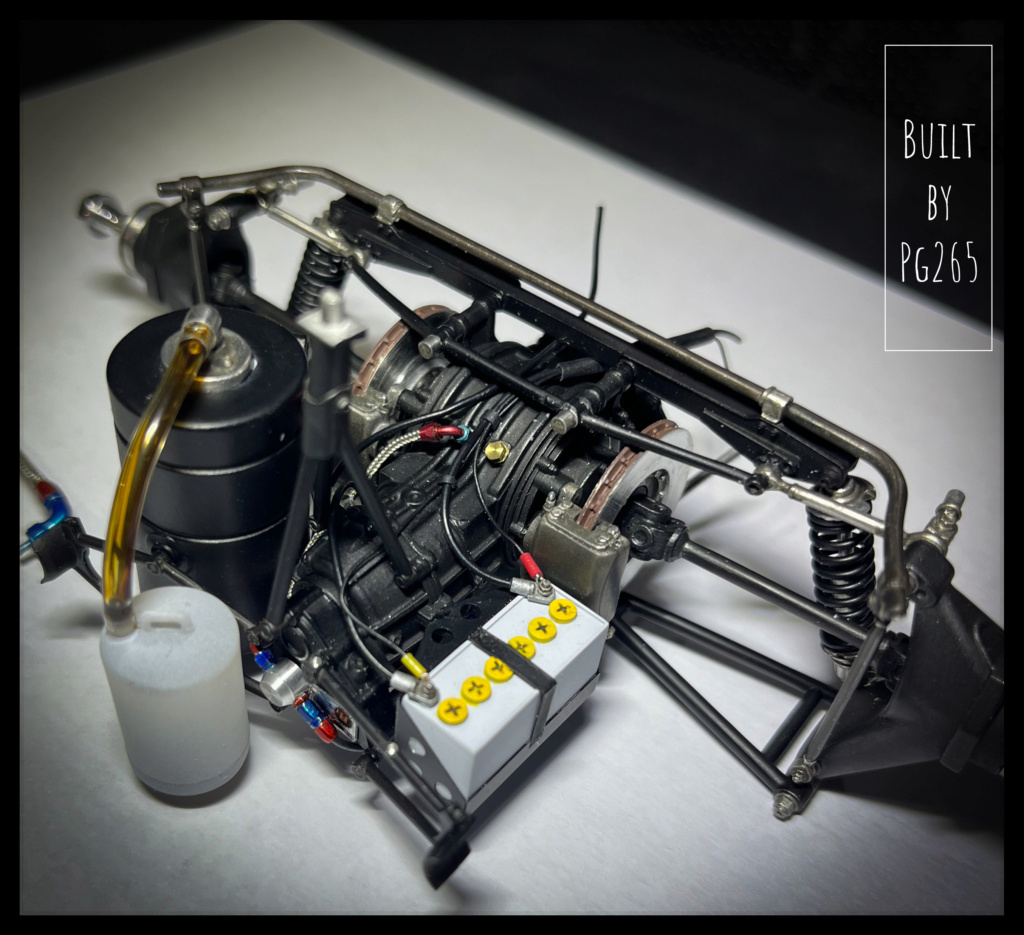
Progress on the gearbox is laborious but rewarding: we are starting to see the end of it!
The battery, its wiring and the starter are done. The gearbox oil circuit completed.
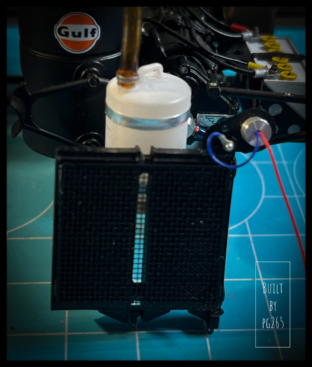
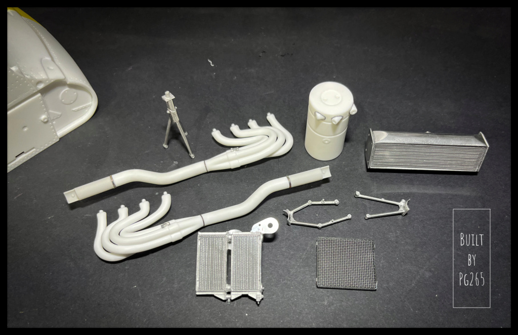
The oil radiators are assembled and equipped with the rear light.
I made a small part for the back of the rear light. It will later be equipped with its wiring.
The oil tank is installed, the recuperator is temporarily put in place: photo-etched collars to be formed should soon fix it and the clamps which hold the hose are on standby.
I made a little “oil” for the hose and the can got a bit of it.
The exhausts are painted.
More soon.
Pascal -
Hi Andy,
I think that 1/20 is far better for F1 kit (my opinion!) and even more for those 50’s to 80’s cars which were pretty small.
MFH made some cars from eras almost never treated by all the other kit manufacturers. Producing them at the same scale than the majority of other F1 kits (1/20) allow you to have a great series from the 50’s till now.
Yes, I already built several 1/24 MFH Sport cars and loved it: Ferrari 512M, 312P, Alfa 33/3 Short Late, 315/335S.
Pascal
-
Hi,
Unbelievable!!!
Pascal
-
Hi,
Cool!! A312F1!
Surely one of my all time favorite Ferrari F1 of that era!
I love the 67, built several and still have two more to do, but the 1968 model is beautiful!
Can’t wait to see more.
Pascal
-
Hi,
Beautiful car and stunning details on the engine: Bravo!
Pascal
-
Hi,
Great work!
Beautiful paint job and a stunning detailing. I love it.
Pascal
-
Hi,
Awesome!!
Pascal
-
Good morning,
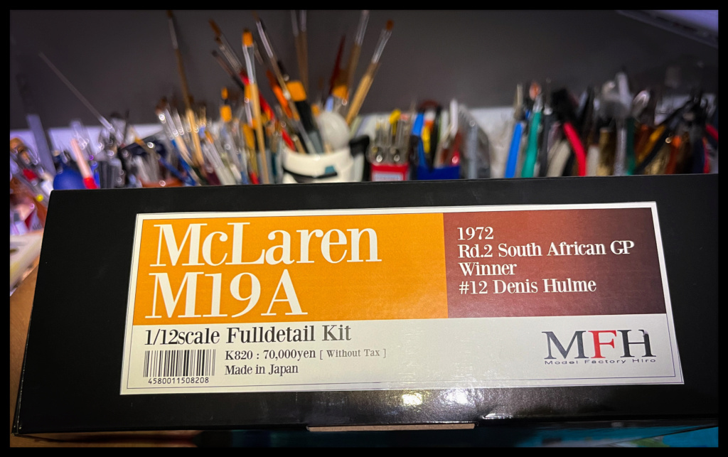
The Ferrari 312B on break, I’ve decided to start this beautiful 1972 McLaren M19A.
I love the car, but would have preferred an earlier version with McLaren colors: the wonderful Papaya Orange.
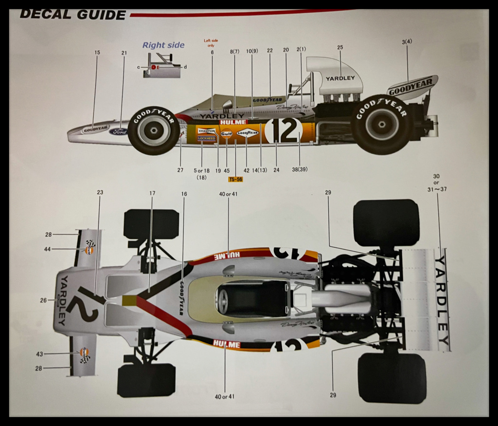
The 1972 South African Grand Prix winner, in the Yardley colours, will be in the hands of Denny Hulme: The Bear!
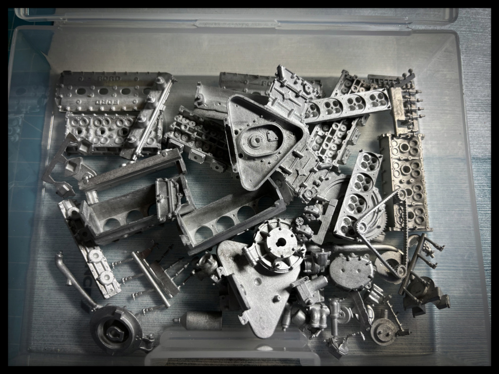
The kit is very nice and rather well studied, finely molded and made parts, both for resin and for White Metal.
The decals are sumptuous.
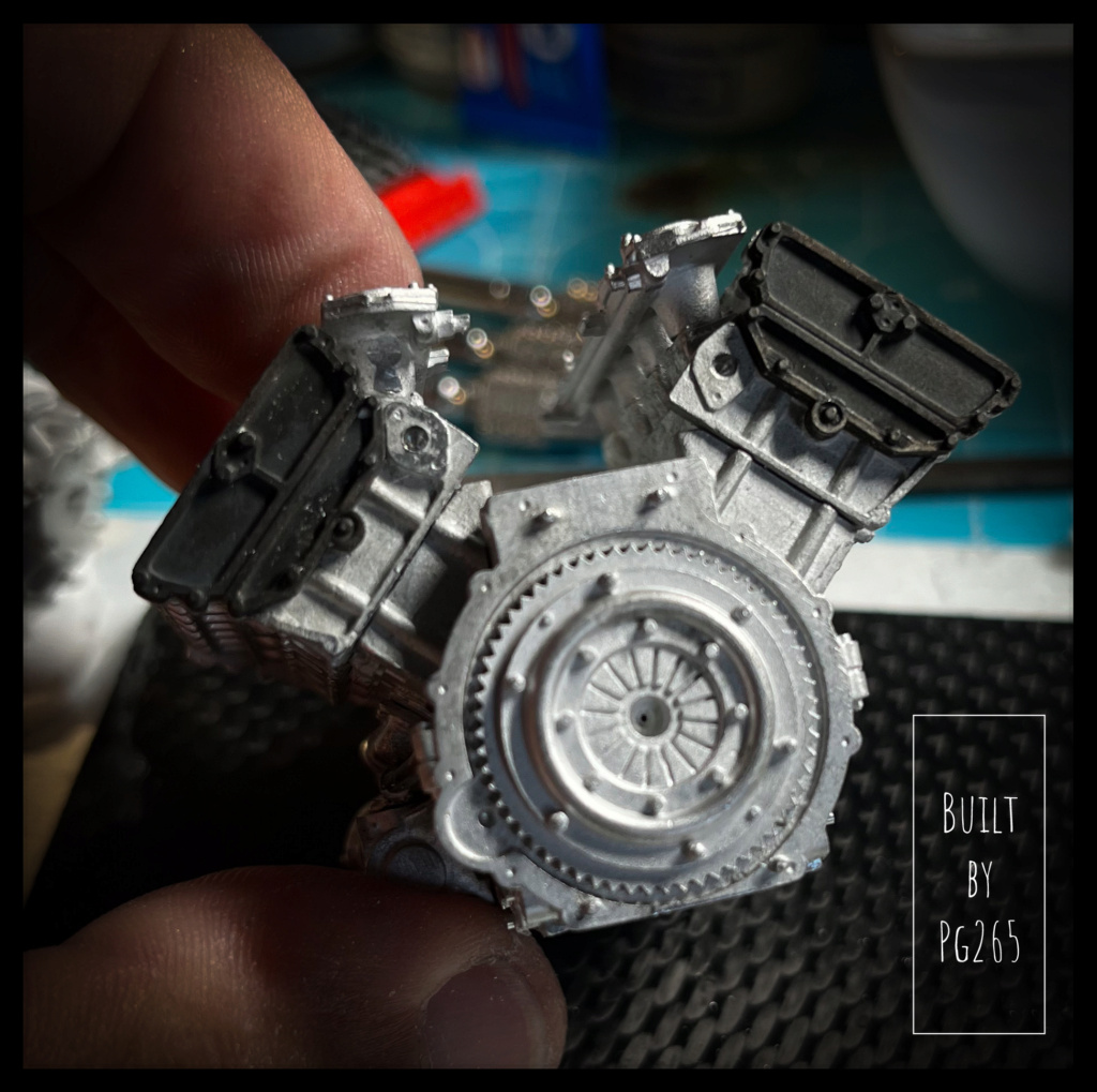
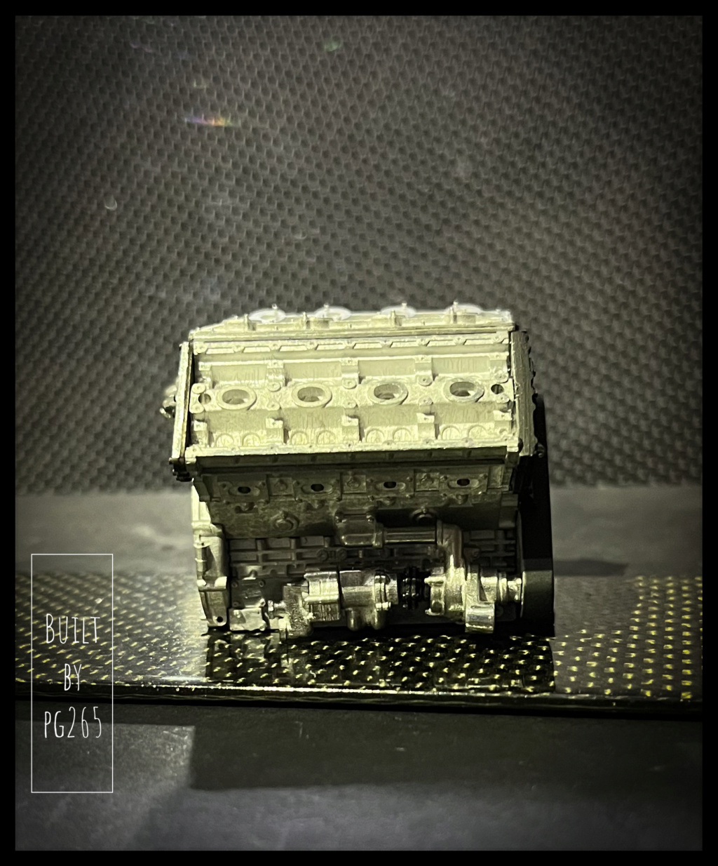
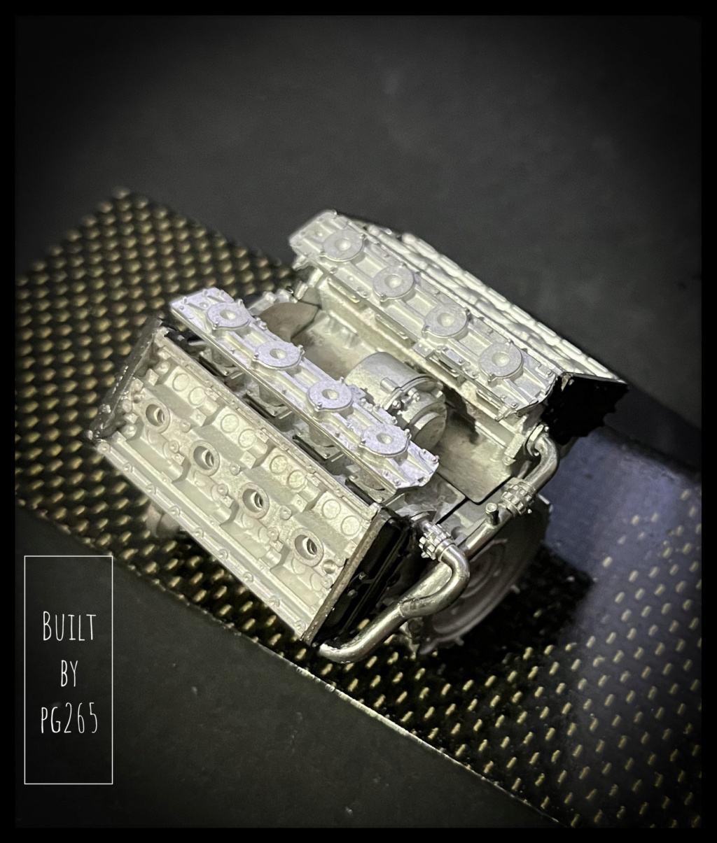
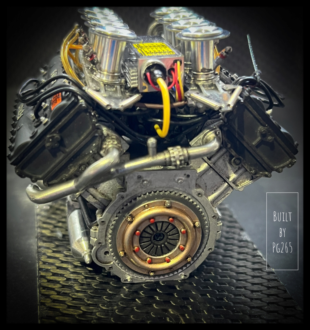
Start with the first assemblies on the engine: A DFV!
I made small blanking plates for the holes of the lower engine not used on this config.
They are made of very thin aluminum foil, drilled and fixed by machined BTR.
Of course, all this will be virtually invisible…
The water plate is also installed and fixed in the same way
Many holes are made for subsequent assemblies.
A part of the accessories is installed on the left of the block.
Some parts are treated with browning.
The clutch is only installed for fun.
In order to ensure good alignments, the box is tested, its inking points on the block adjusted: Not too bad.
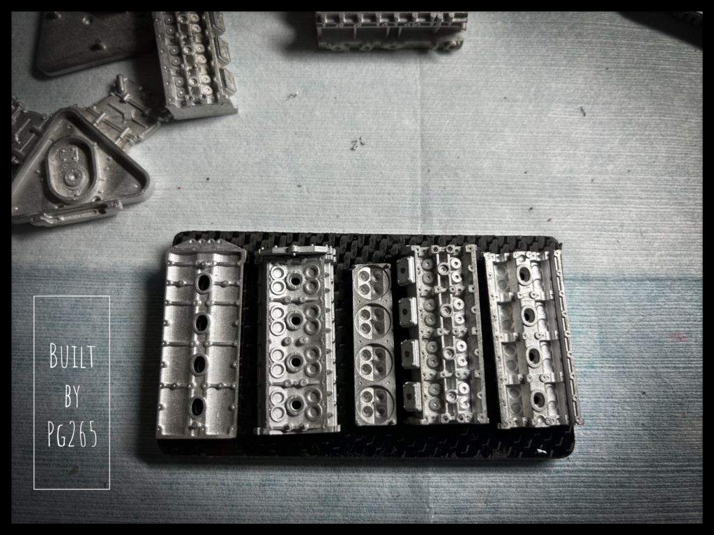
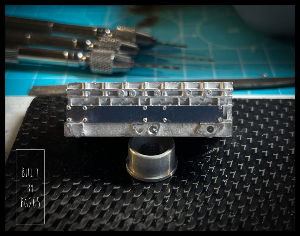
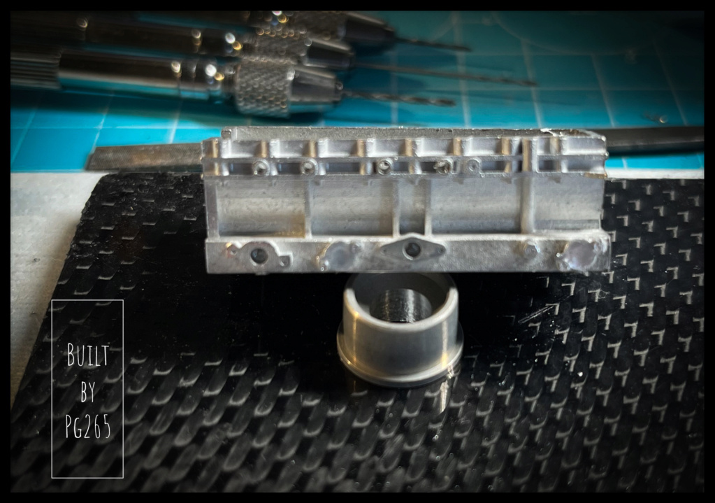
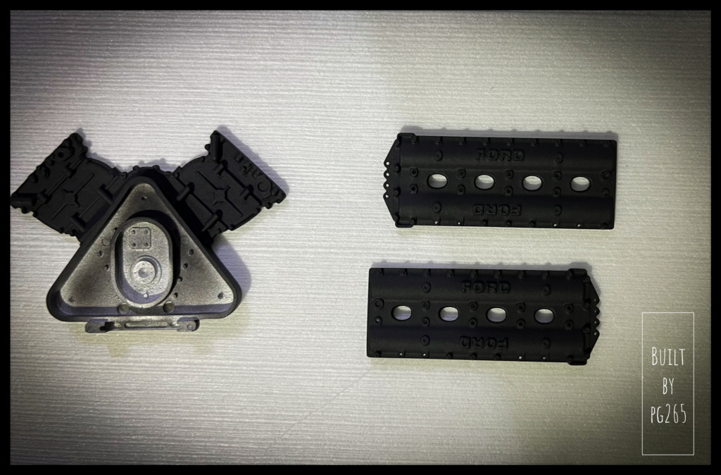
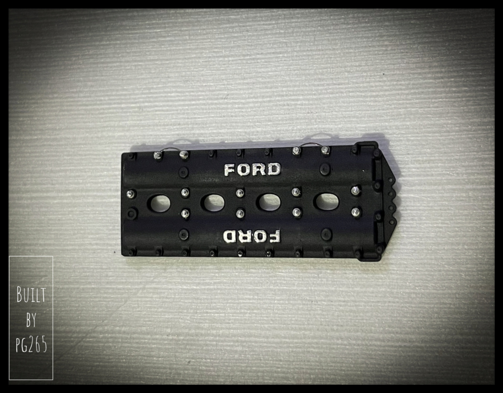
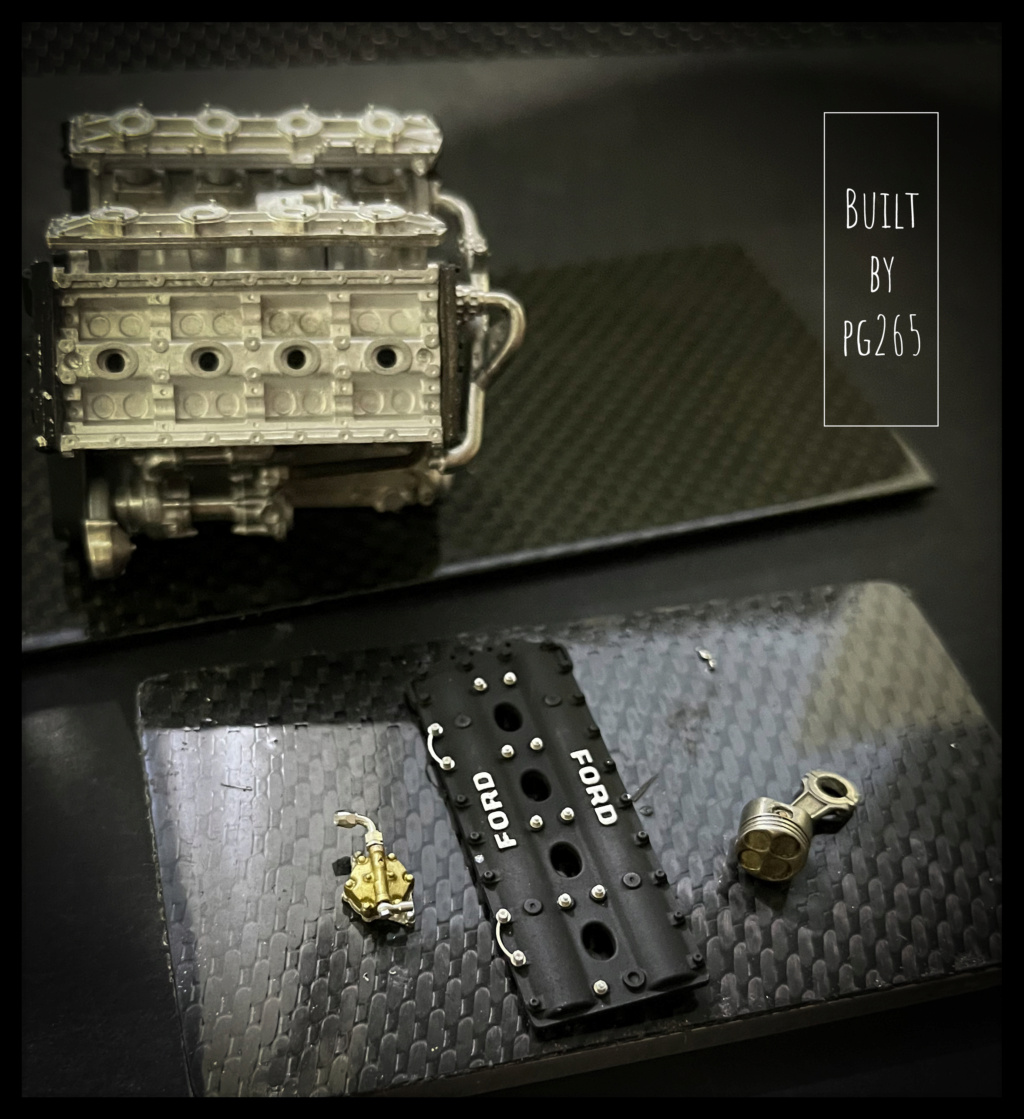
Well, it’s not all that, but I worked a little on housings/crankcase of all kinds.
Those from the waterfall at the front of the block and the friends who hide the camshafts.
First a few holes, of different diameters, very light sanding and polishing on the Ford logo and masking with gum for artist.
Then a little prep.
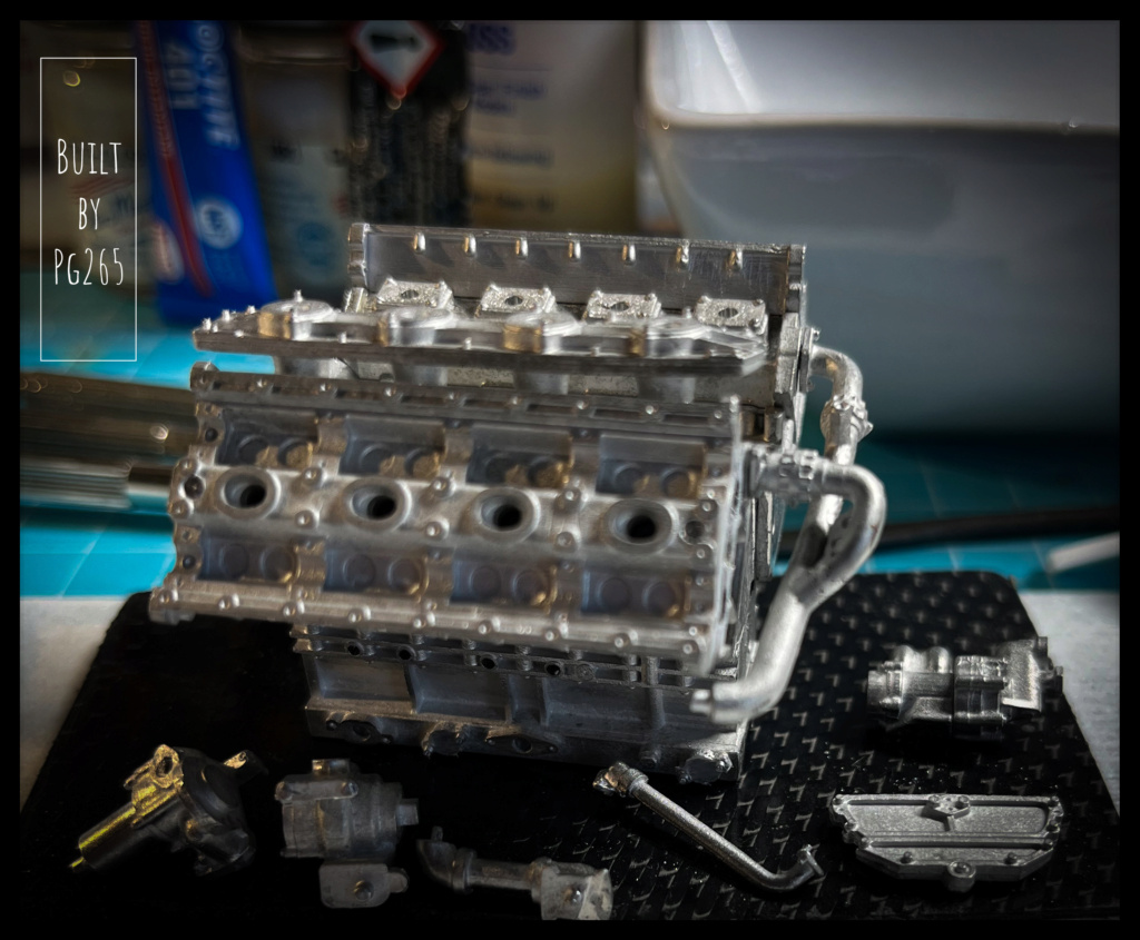
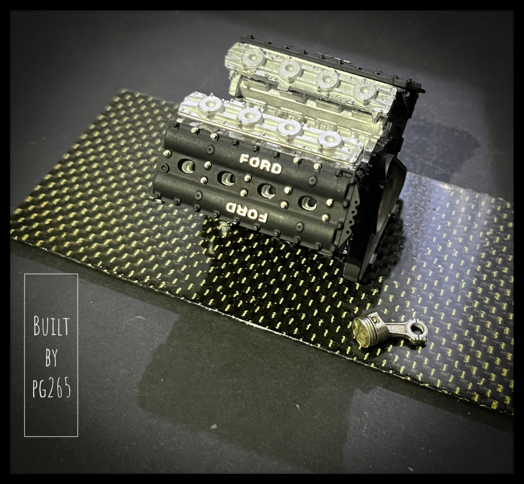
The right side is equipped with its accessories.
The water pipe, in 2 parts, is welded and polished.
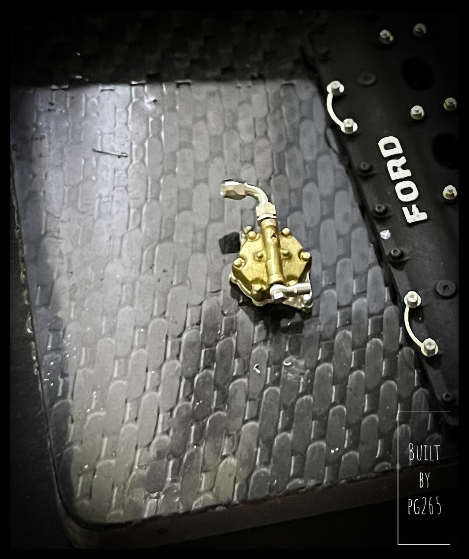
One of the fuel pumps (attached to the block and mechanically driven by the block) is modified, painted and equipped with a Banjo fitting and an angled AN fitting… both made of machined aluminum.
The transition of different shades to oil will give a little life to all this little world very soon.
I must admit that the assembly of this model requires a certain habit/ experience of kits of this type.
The plan shows pieces whose fixing points/pawns are missing from the physical parts. Many modifications and tricks must be used to achieve the “desired” result.
A good knowledge of the engine as well as a good documentation are also necessary to realize connections,
missing connections/hoses and other wiring.
For example, the pump I just installed is connected to the electrical pumps in the bulkhead and the tank, but not to the filter and the injection pump, both of which are present and detailed…
This is, I think, the first model from MFH that gives me these small inconveniences.
But hey, we’re not gonna complain, right?
The kit is sublime, like this car that I particularly like!
If only an M7A showed the tip of their muzzle…So, let’s close this parenthesis…
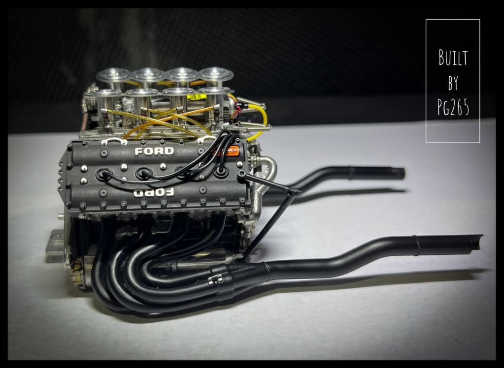
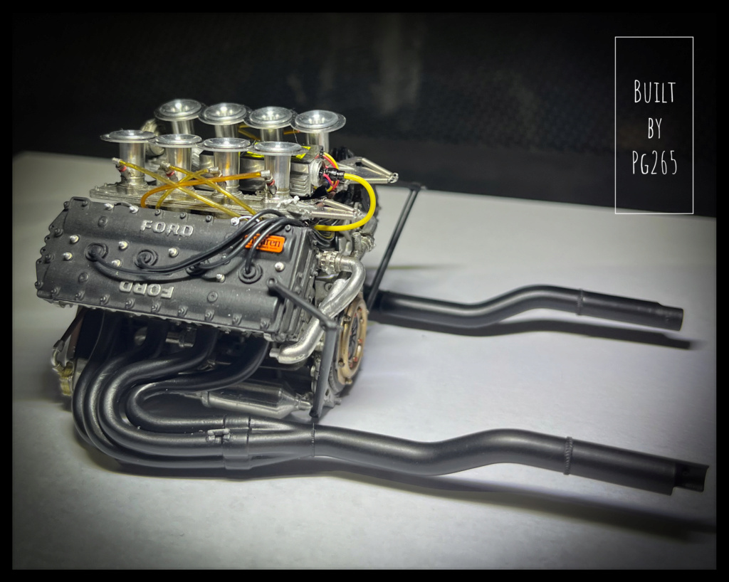
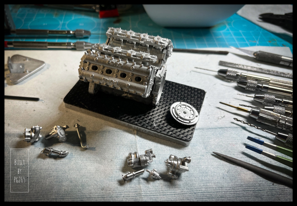
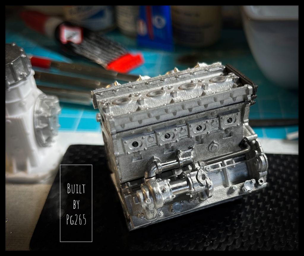
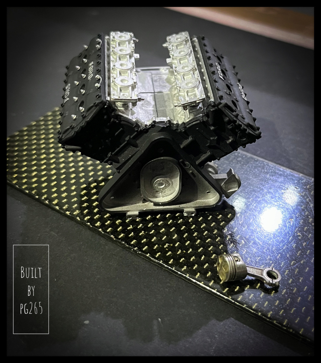
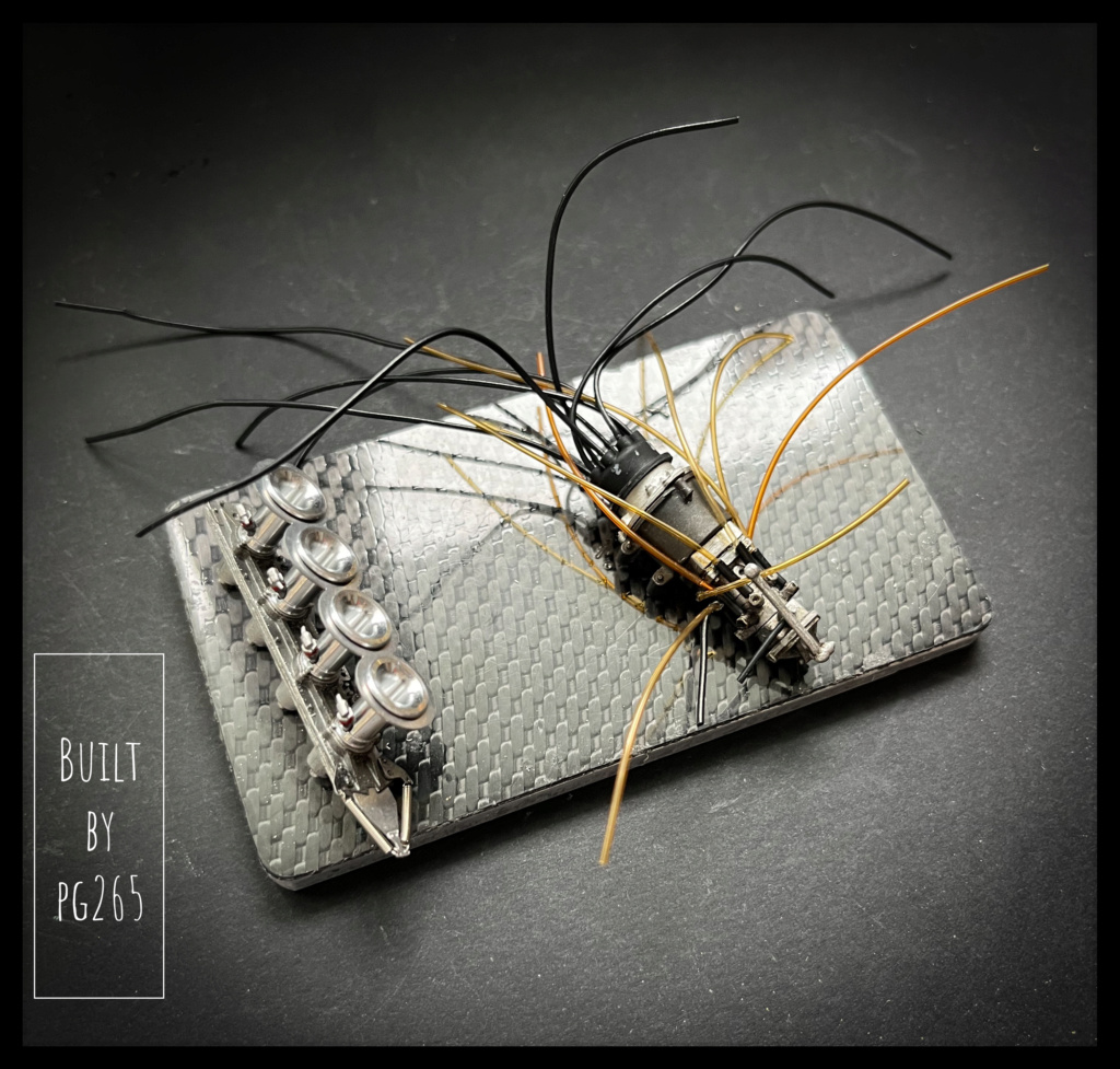
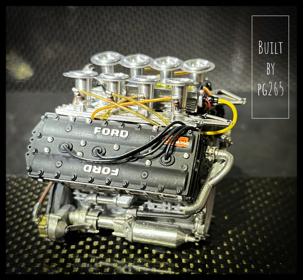
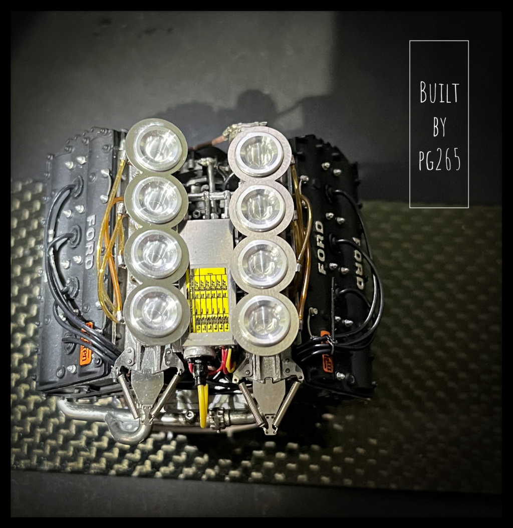
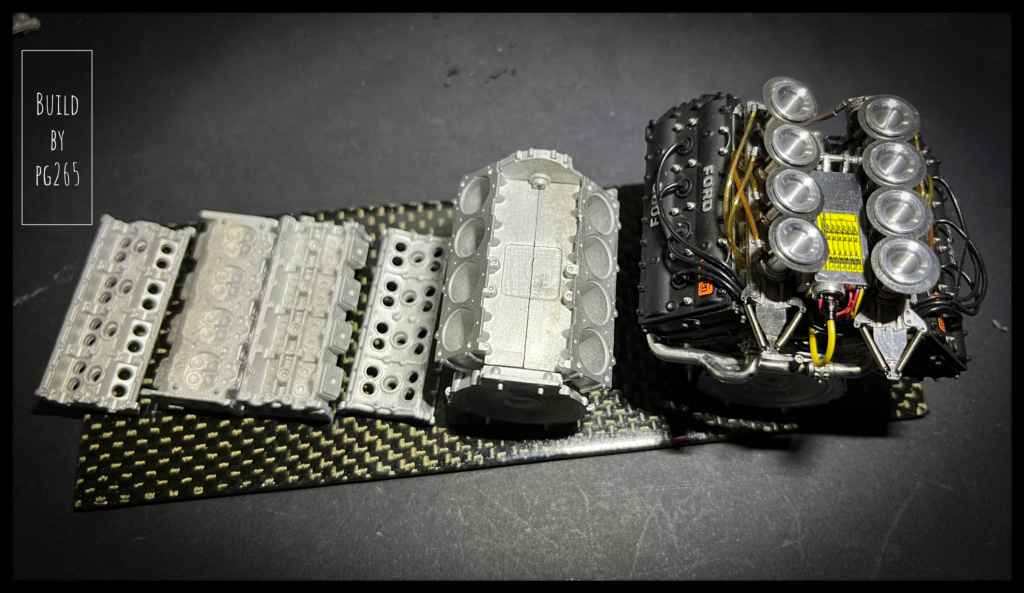
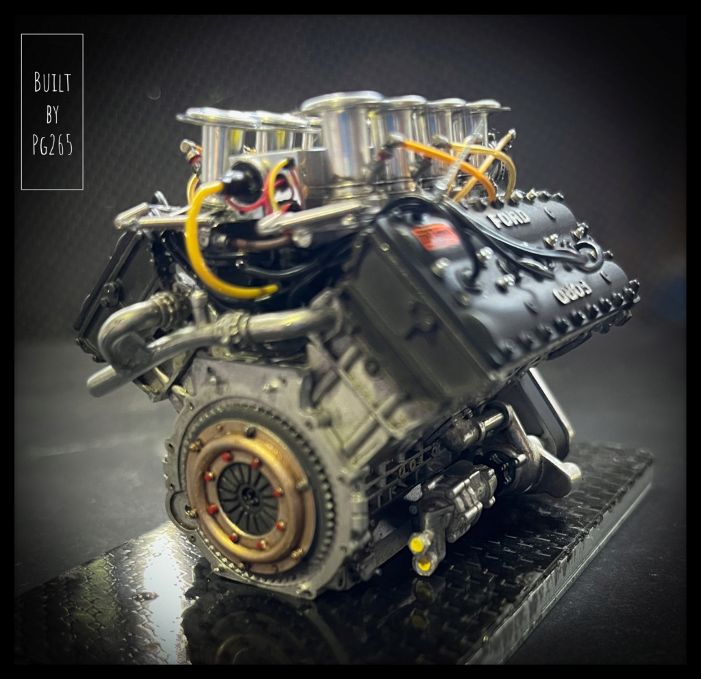
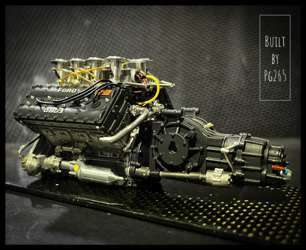
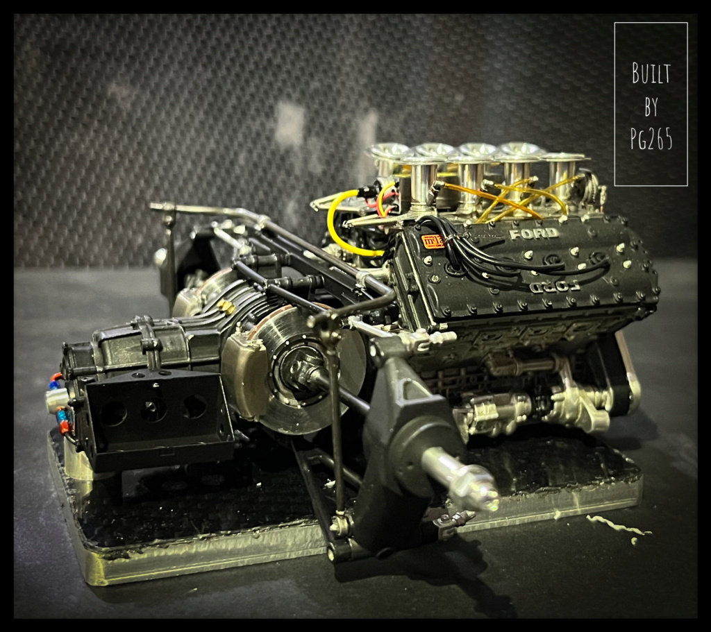
The Cosworth block is progressing.
I have made some details and quite a few changes.
The vast majority of cables and hoses are not those provided by MFH.
The entire power circuit is reproduced.
The assembly of the admission ramps is not so simple because of the high room through which the trumpets pass.
It must:
- pass all the trumpets,
- stick them on the guillotine ramp (taking care to properly align the injector openings)
- turn the assembly and center the upper piece on the trumpets and stick it inside the capillary openings on the trumpets… without burrs and other traces of cyano.
A very fluid glue was used for this.
Pretty good, even if I’m not more satisfied than that…
The DFV engine of the Lotus 49 at the same scale is really of another quality, at all levels.For fun and because between the two my heart swings!
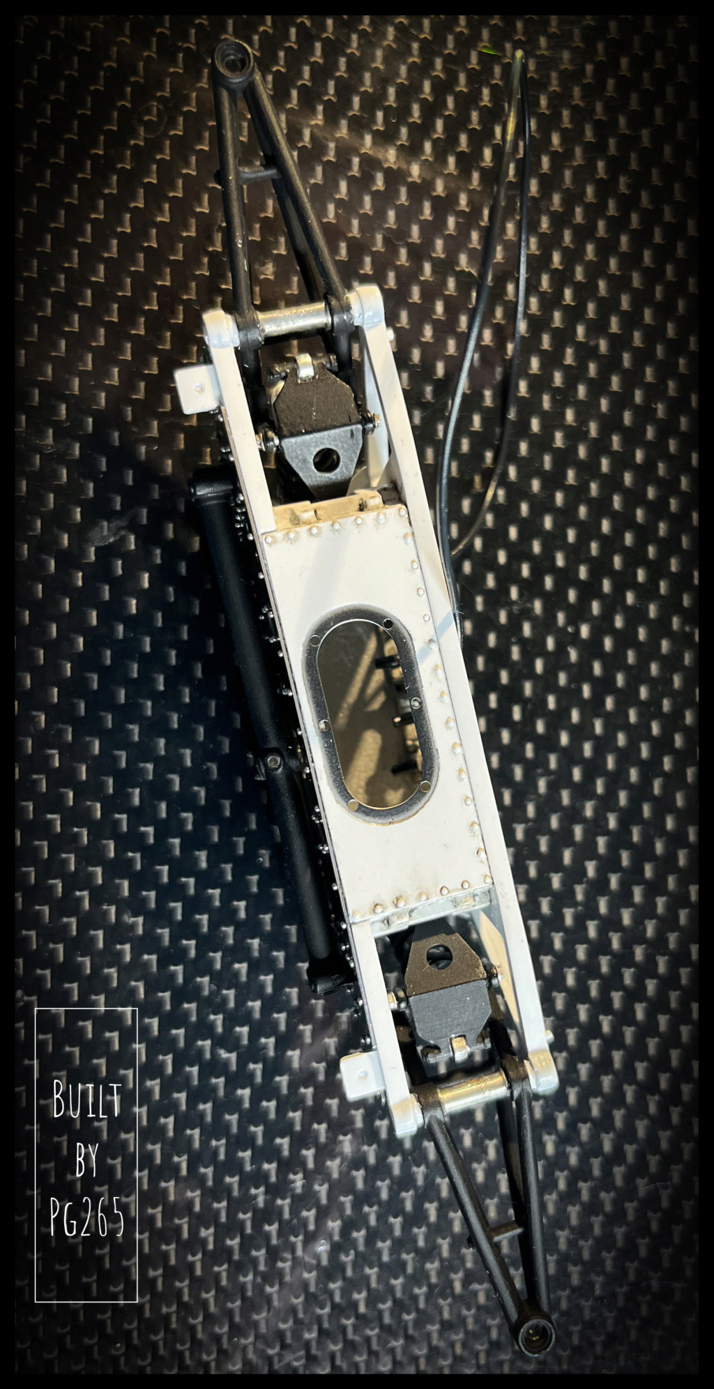
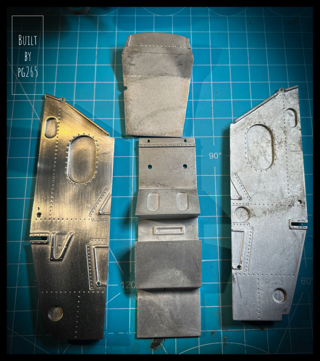
I started working on the hull.
It is a composite assembly of resin and White Metal, mainly screwed.
It’s more work than it seems.
It is therefore necessary to drill all the elements according to different diameters according to which the part must be threaded or only to let pass the screw... and therefore tap in 1.4mm mainly in metal and/ or resin.
The «bathtub» will also be welded once its parts polished and riveted.
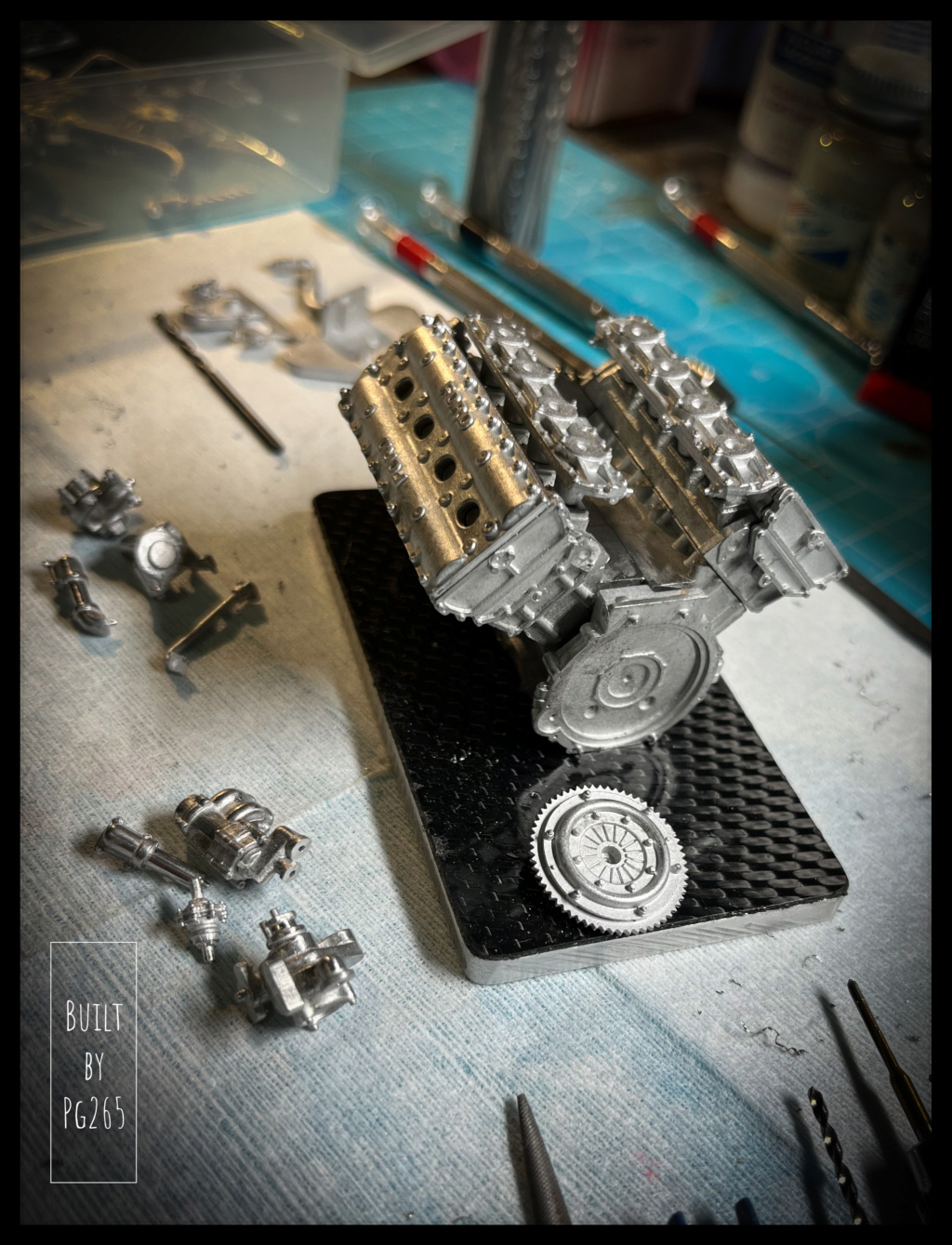
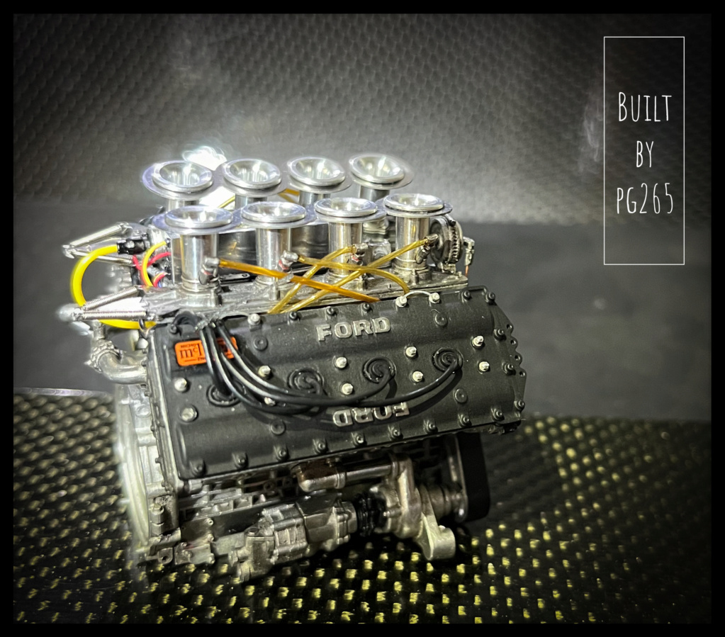
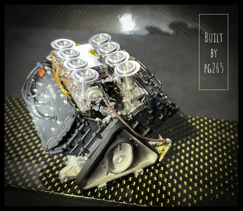
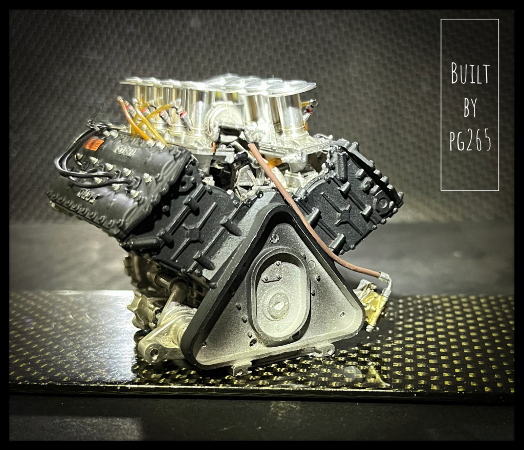
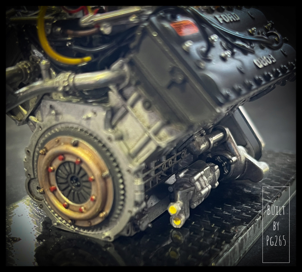
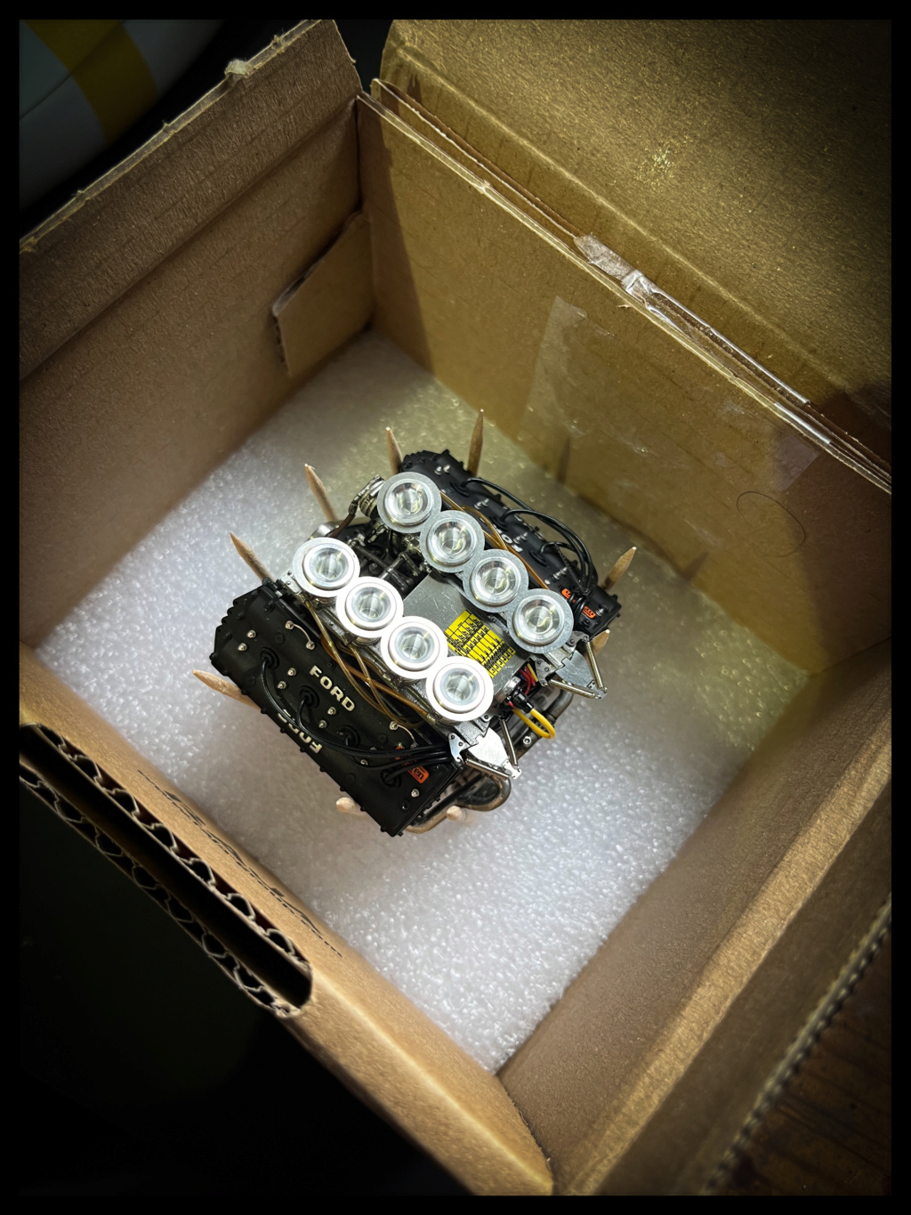
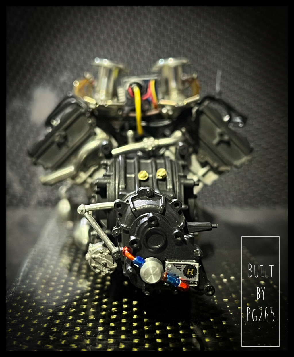
We are still far from it!I decided to bring the engine for an exhibition in Niort.
So it took, for fun and a better presentation, to finish it a little better.
- Front plate installation,
- Painting and treatment of the steering wheel/clutch assembly,
- Installation of yellow "plugs" on oil outlets.
The dark parts are treated with Blaken'it, rubbed and passed in oil.
the «golden» part is painted with Humbrol Metal Cote, little pigmented to obtain a certain transparency of treated metal.
Two/three details and transplants, and zou!
It’s clean, it’s not too bad.
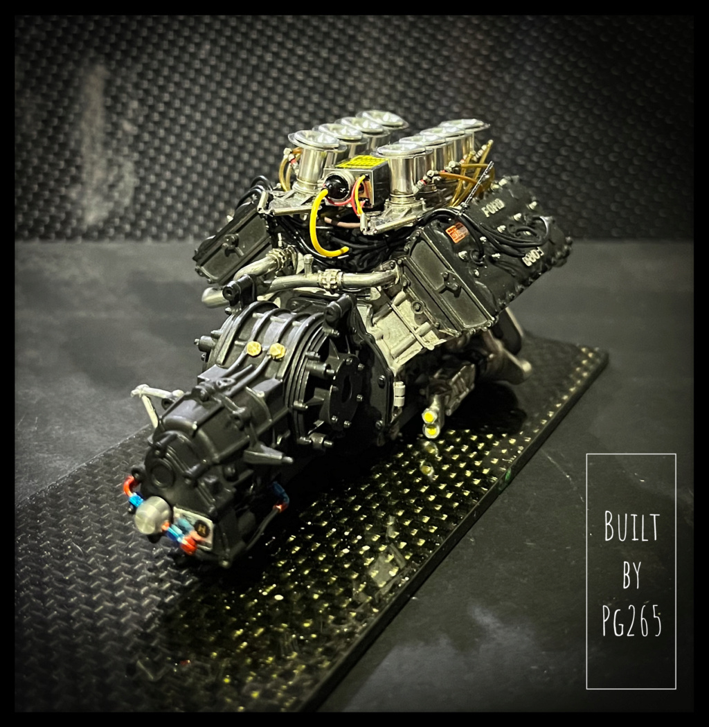
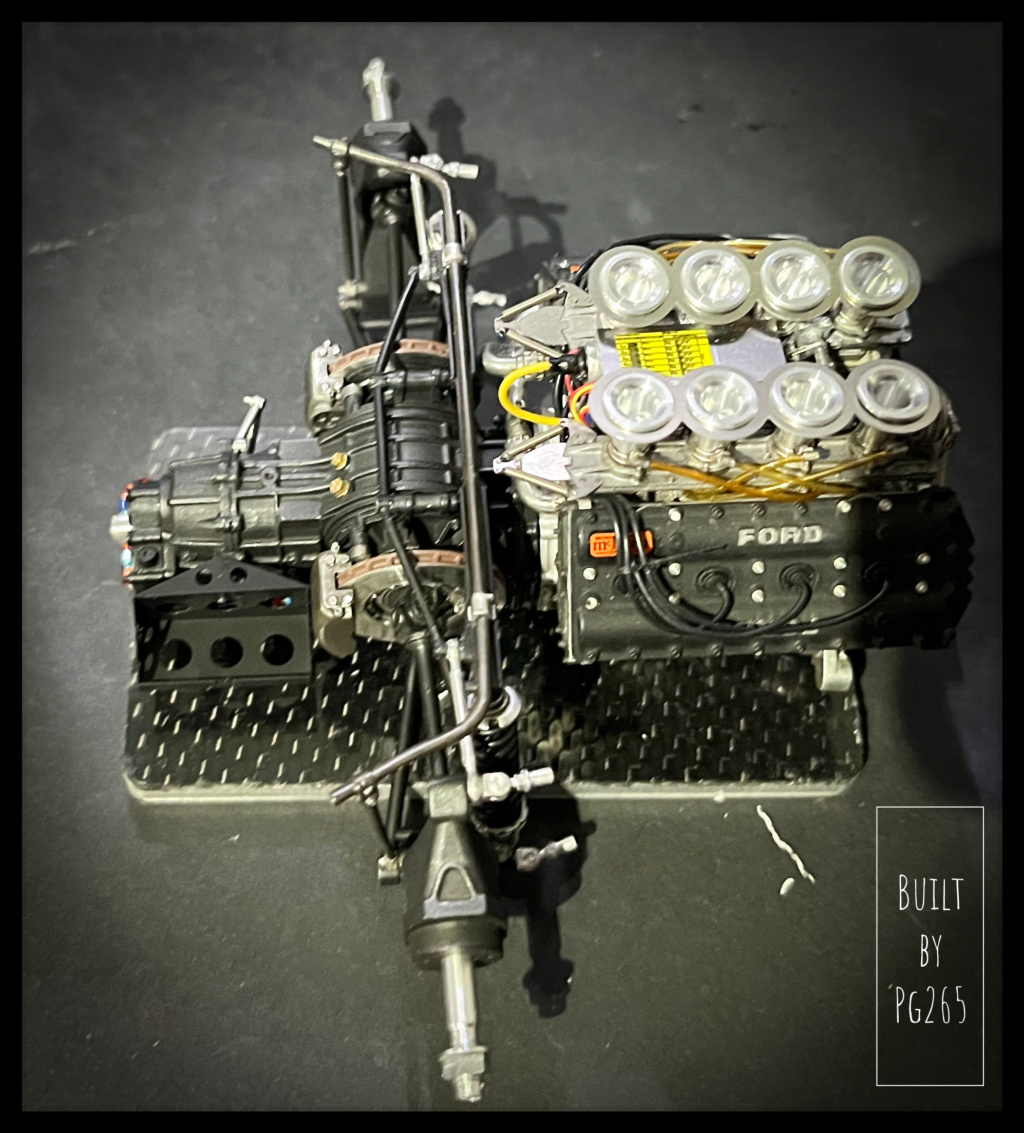
The set will go back into the rabiot box when assembling the gearbox.In his box for transport.
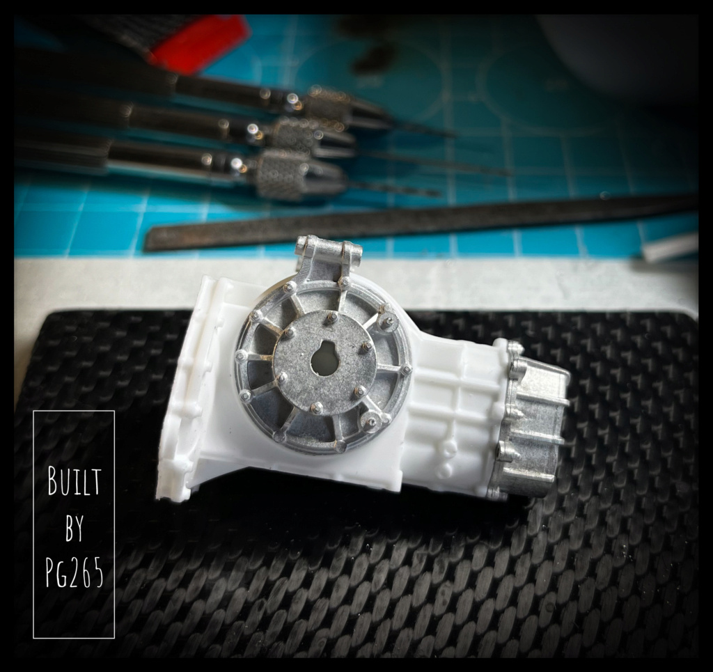
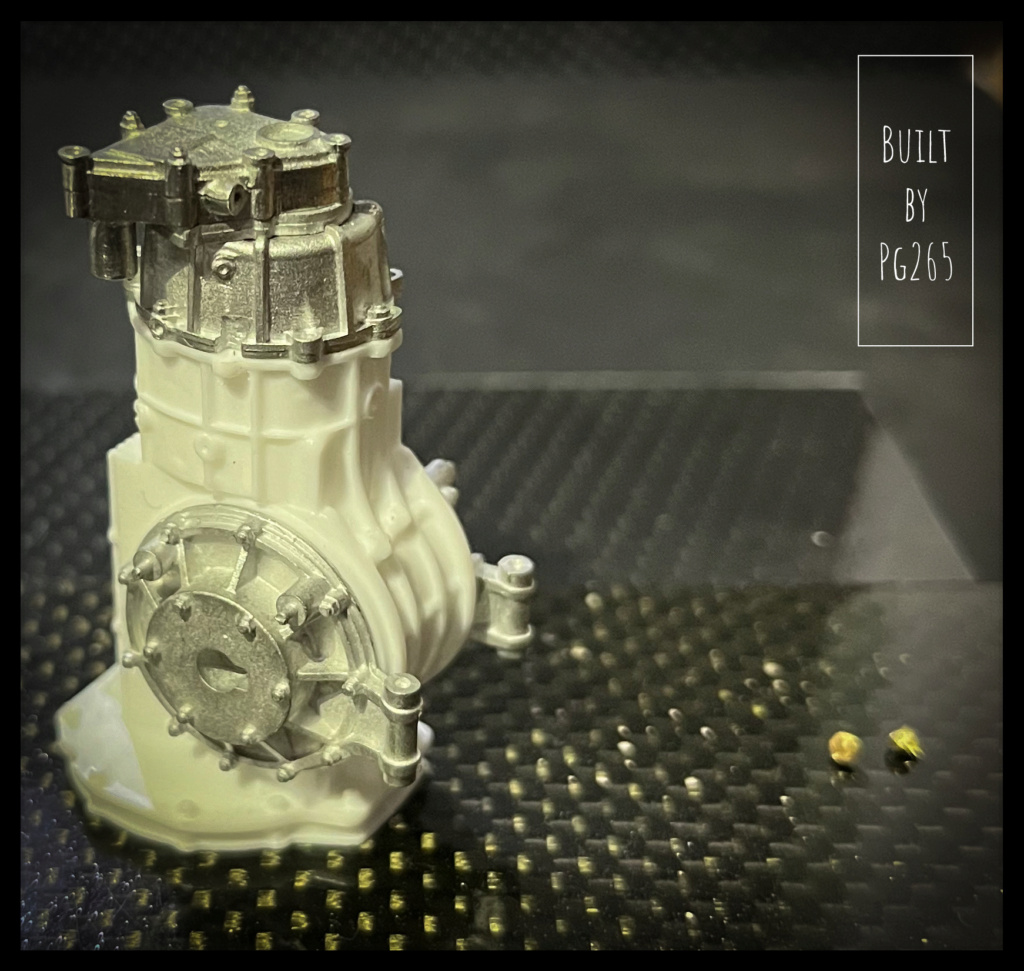
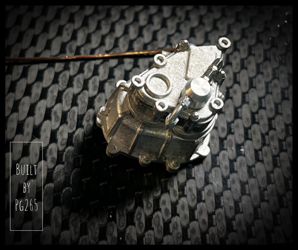
GEARBOX!
It is not spectacular in the photo, far from it, but it is the whole with the addition of what will be connected on or assembled around.
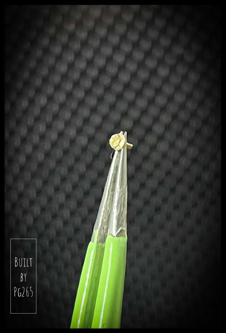
I also needed brass bolts/washers (ø1.5 and 2mm) for the Hewland box.
Of course… nothing!
So I machined them.
The picture is… Bad (!) to say the least, but I will try to make better ones in the situation on the box.
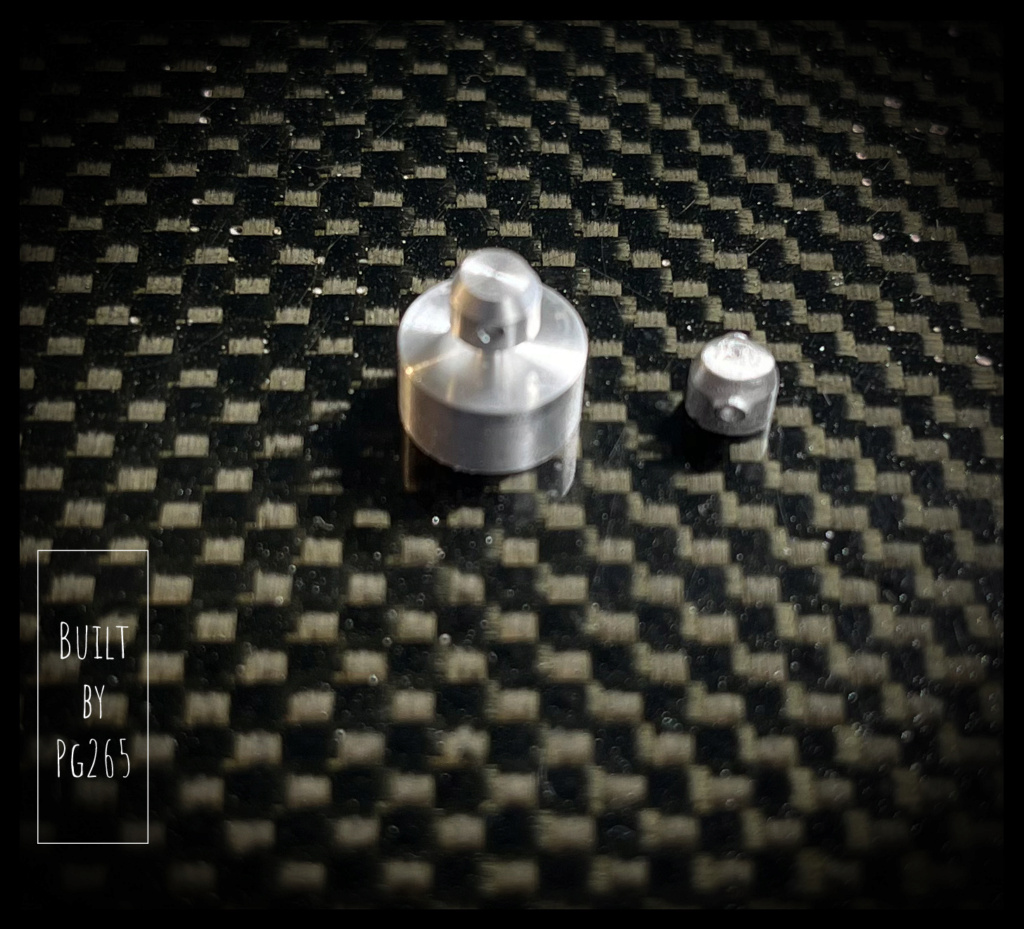
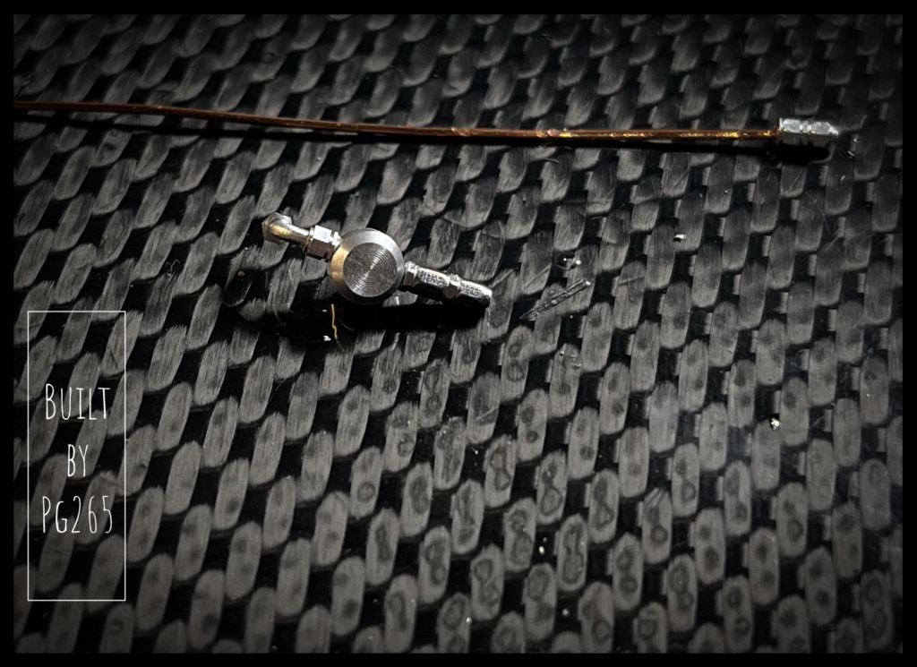
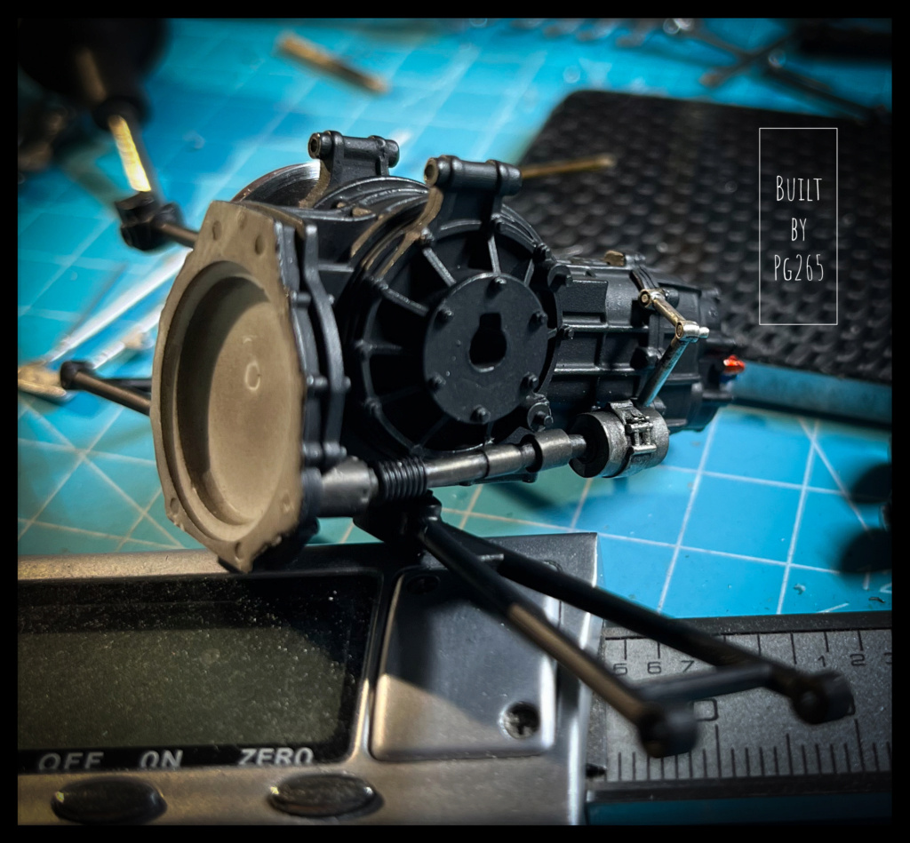
As I was in the DIY mood, I decided to redo the pump at the rear end of the gearbox.
It is turned into a remnant of aluminum log, then pierced.
It is 4x4mm.
Test fit of the machined brass parts on the box.
I took the opportunity to machine straight A/N fittings: to improve, but not too bad.
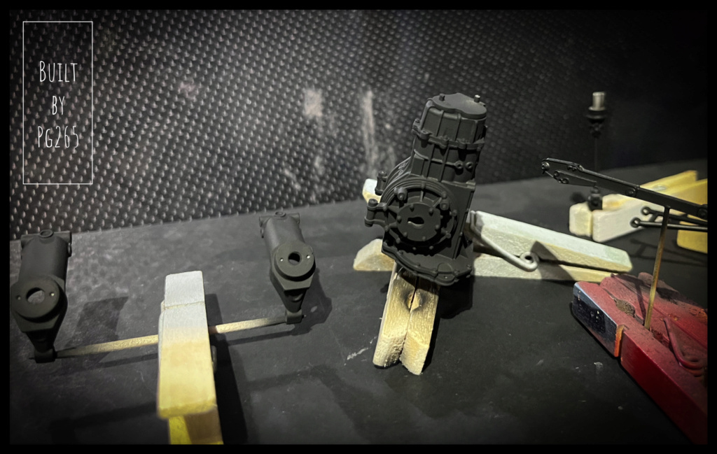
In order to be able to assemble and paint most of this set, a lot of preparation work, drilling, tapping… is necessary.
Once satisfied, the parts are primed.
Then painted in various shades of black.
The Hewland casings are given several shades of oil and the A/N fittings are partially painted.
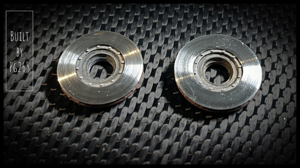
I mounted a disc and made a tool to be able to install it on the lathe to finalize its appearance.
I’m starting to have a few tools as I make one for each model.
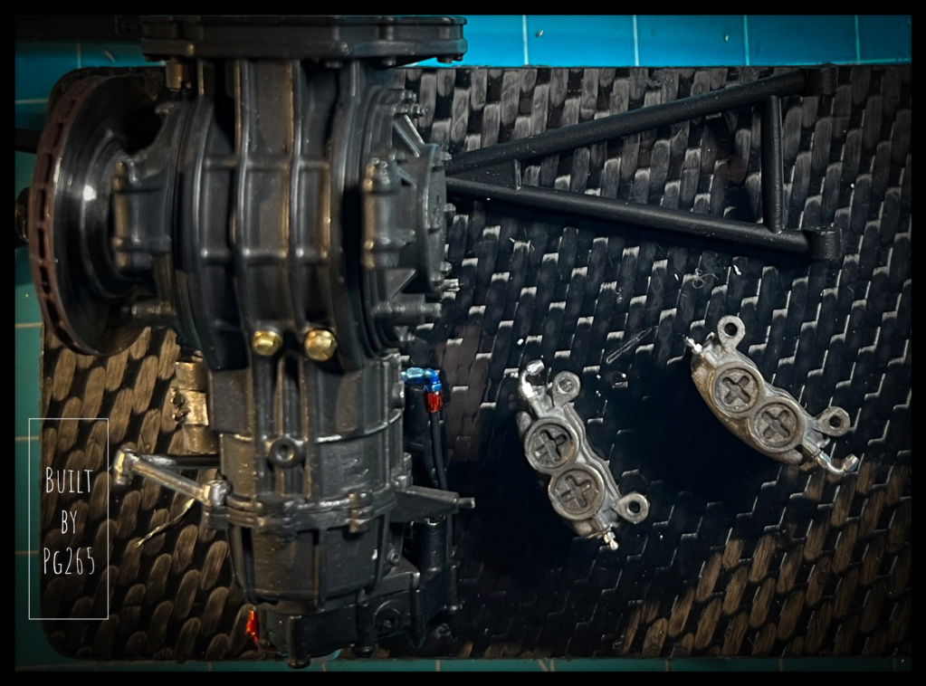
Other parts such as calipers and starter elements are treated with Black'it, rinsed and brushed.Always many tests, adjustments, drilling…
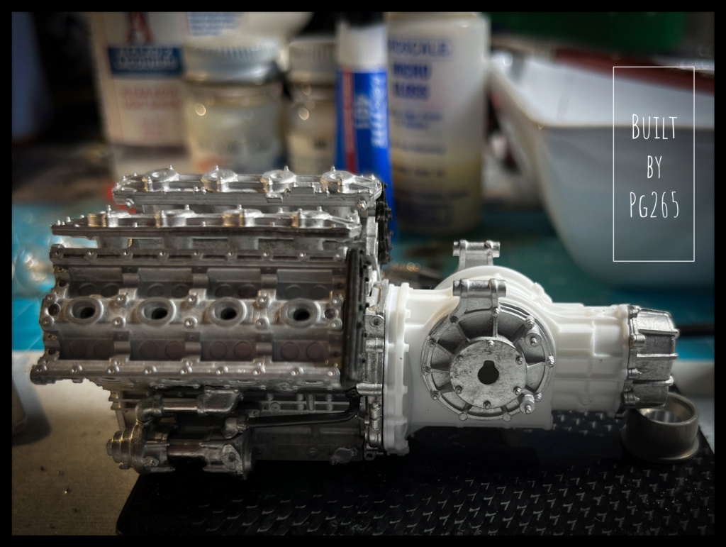
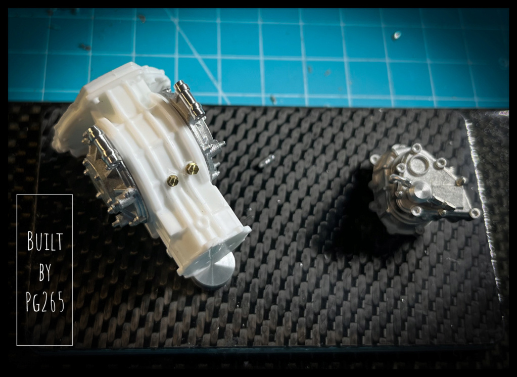
Blank mounting to validate sub-assemblies.
I made the identification plate of the box in a very thin sheet of aluminum, Speed Tape in fact.
It’s a little more realistic than painting in aluminum the relief of the box end part.
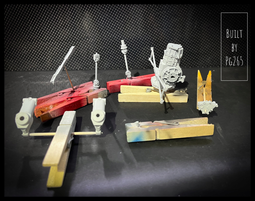
I apologize in advance for the quality of the photos that follow: it is late!
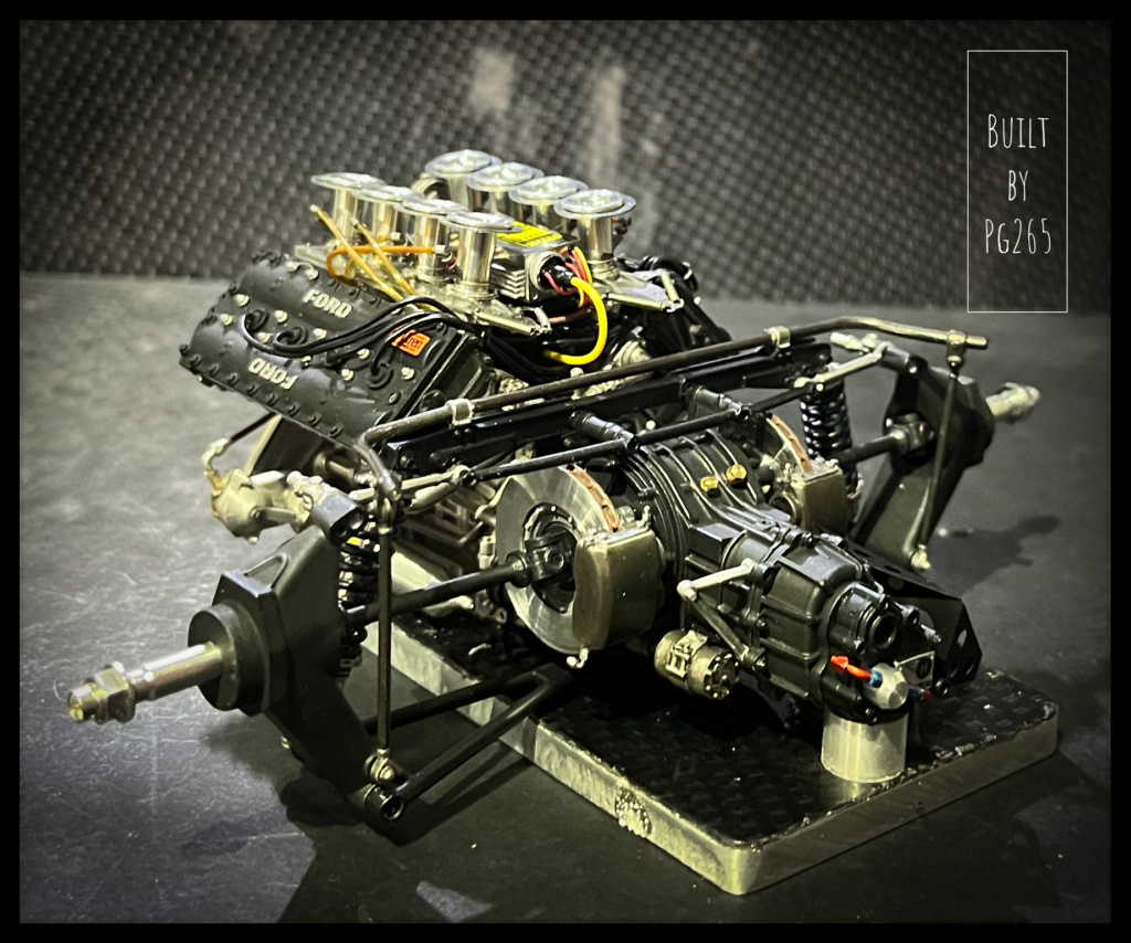
The assembly of the gearbox continues.
It is a set that seems simple, but is not because of all the elements of the rear axle, brakes, transmission.
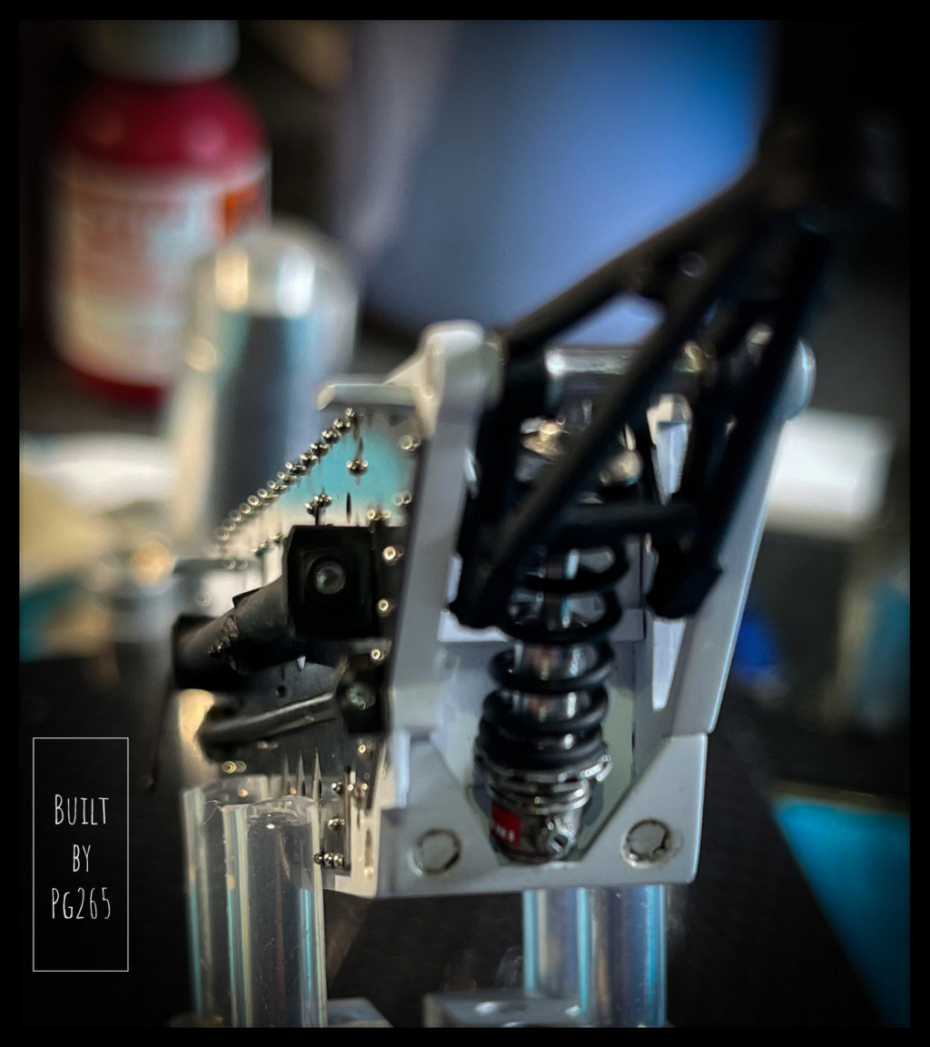
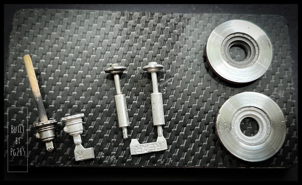
As I said before, preparing the elements takes time.
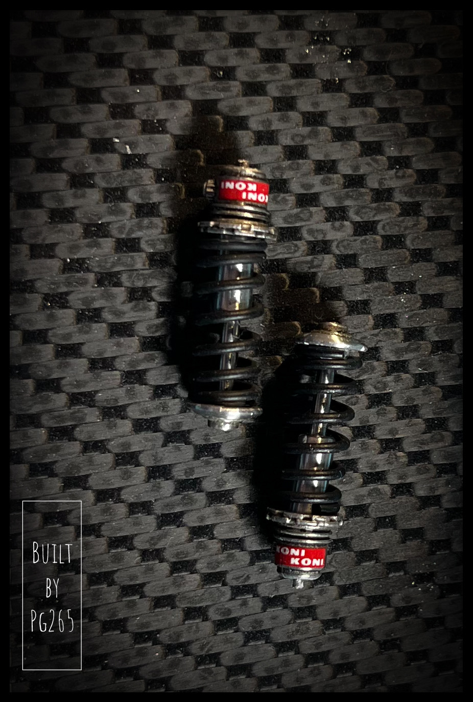
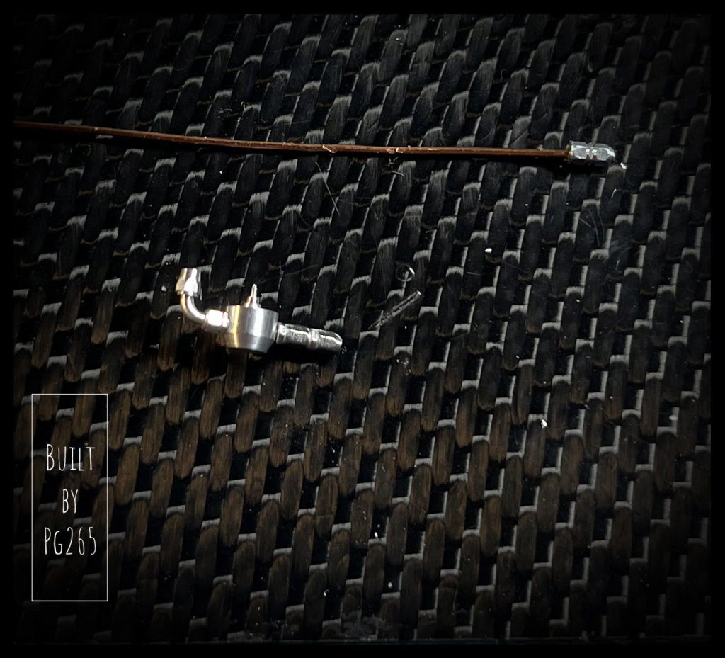
To illustrate my point, here is the image of a shock absorber being prepared next to a “raw”.
The first photo also shows the records… But, by mutual agreement with myself, it was decided to bring a little more detail.
So I drilled the internal flanges to install Allen hardware.
As long as one is engaged in the detailing, the calipers are equipped with their bleeders and fittings for the brake fluid lines.
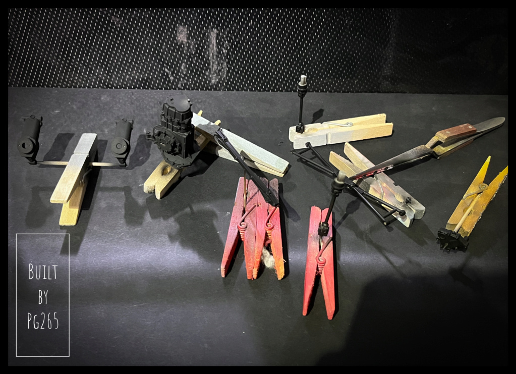
All suspension elements, springs.. , were primed and painted in satin black.
The stabilizer bar and its rods are brushed and then chemically browned.
Everything is finally assembled.
It remains to refine some details with oils as usual.
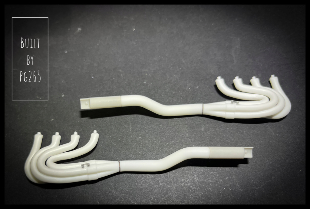
The battery tray (photo-cut part to fold) is installed temporarily.The exhausts are done.
A small weld is added as well as the tab that holds the 4 in 1 on the collector.
The outlet is only temporarily installed because it must be aligned with the support that will be installed on the box.
The printed parts are hallucinating finesse and precision! The spectacular and splendid exits of the 256F1 had already left me speechless!
Here are the elements waiting for some black (satin, matte or a mix of the 2).
The exhausts are finished, the welds added.
The radiators are much better than other models: White metal for the filling and photo-etched grille.
The result is very satisfactory and should be quite realistic once the satin black is applied.
For more realism, I represented the welds on the oil tank.
More soon.
Pascal.
-
Buongiorno a tutti,
It’s the return for the 312B…
You still have to get back to it one day!
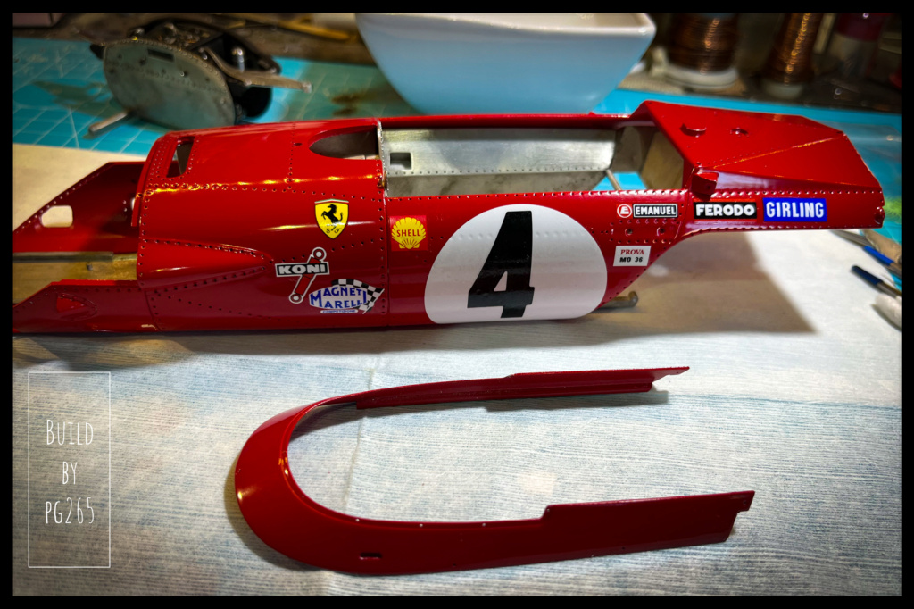
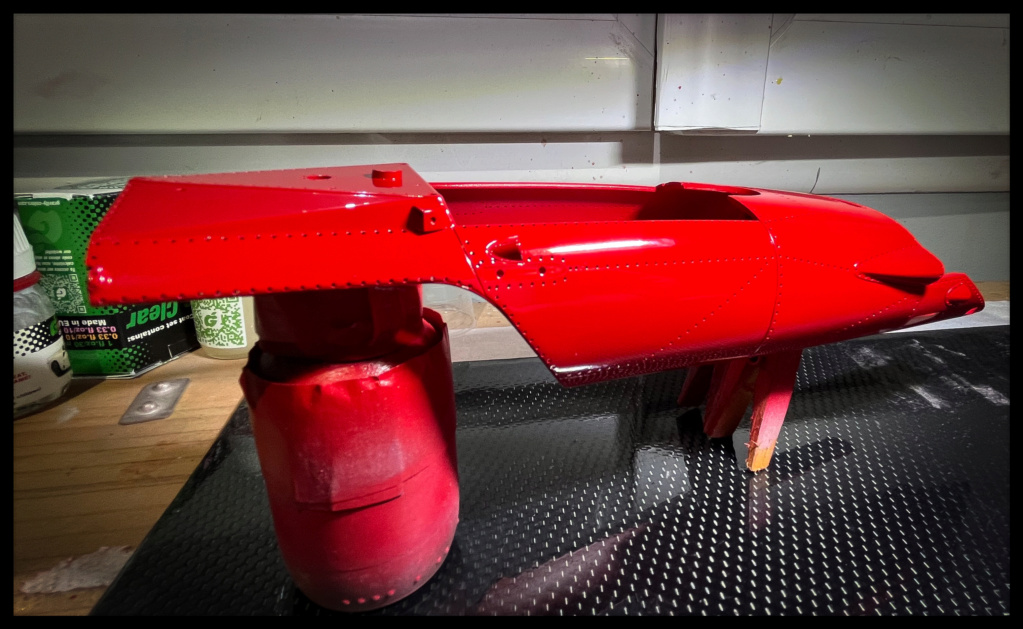
Deco day: decals are applied to the hull and muzzle.
The upper part will be decorated after cutting the windshield which will require some tests and manipulations.
The hull will also be extensively handled, but the delicate adjustments have already been made.
It will also be very heavy once the main elements are installed; decorating it at the end would not have been wise or comfortable.
More soon!
Pascal-
1
-
-
Good evening,
Thank you Mates.
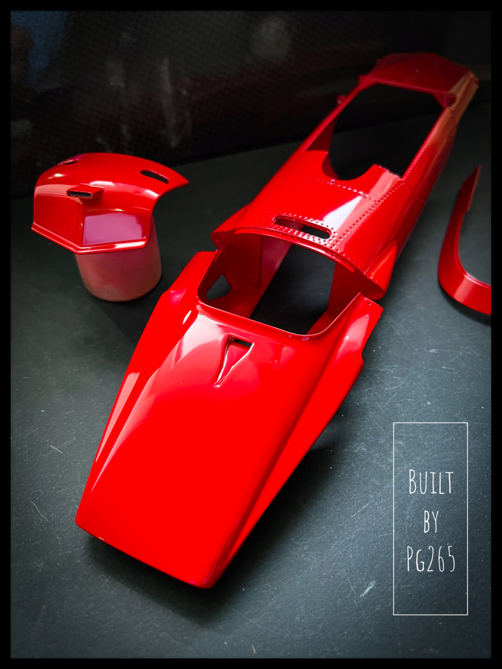
Clear coat is not too bad.
As expected, the holes for the rivets to be set are « re-opened » due to the several coats of primer, paint and clear coat and a soft cloth is passed over to erase fingerprints.
I'll maybe start the decals of the "Bombinette" tomorrow.
Pascal-
3
-
-
Good evening,
THANKS a lot.
Ok. So now the clear coat is done: it dries quietly in the boxes.Next soon.
Pascal
-
1
-
-
Good evening,
THANKS!
I didn't like that much to have the white circles clear coated: too shiny for them.
It was fun to do though...
… and to undo!
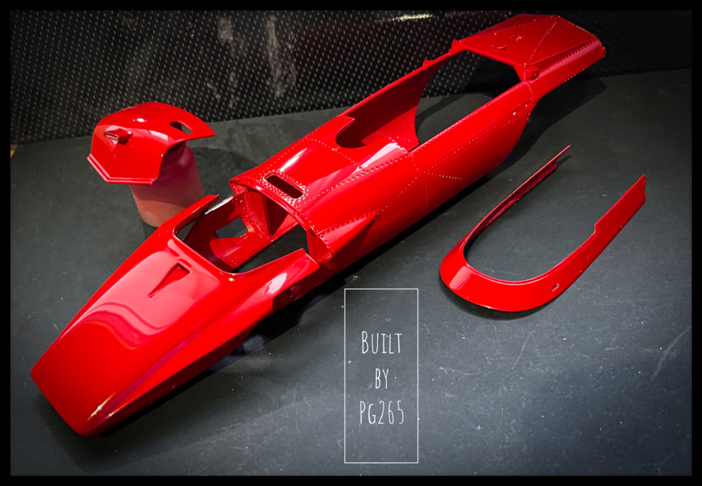
Once again pink undercoat over the sanded areas.
Then Rosso Corsa.
Do and undo…🙄
Although used to Gravity products since their creation, I am always amazed by the grip and the solidity of the paint and the primer, not to mention how so thin they are: a joy!The clear coat should be on soon.
Pascal -
Hi,
Thank you!
Different brands, shapes and sizes of resin and metal rivets were used on this one… and on all my other builds.
I used rivets from Calibre35, MasterClub, Scale Hardware.
0.5, 0.4, spherical and flat spherical.
I use a thin tweezer to hold and insert rivets in their holes, glue them on the backside with CA glue and cut the back with a S&M 15T blade.
An Xacto #11 is used to separate the Calibre35 rivets from the base/sprue, as well as those from MFH which were used for the 256F1.
Pascal
-
 1
1
-
-
Hi,
Clean build and nice paint job and details.
Pascal
-
Hello everyone,
Thanks a lot Codi!")
Back to business, the 312B and I, after a short break.
Pleasant temperature, a little rain, flights for the day cancelled:
Let’s go painting!
I'm still doing a test with the rivets that I'm going to use before taking out the airbrush.
That suits me.
I prepare the material and mix a little paint for my undercoat: pink this time.
…and finally, the Rosso Corsa an hour later.
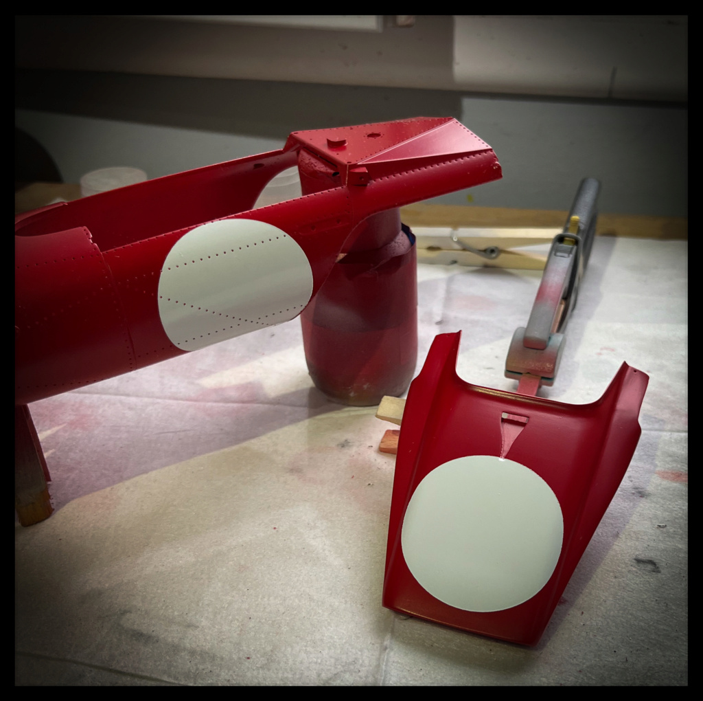
In order to prepare the installation of the race numbers, I decided to paint the white circles... as a preamble to the decals... or not.
So we wait a little over an hour after the red coat, make masks and camouflage.
…And spray the white.
Then unmask quickly, the time to clean the gun.
It will be easier to count the number of white rivets needed.
Voila, voila.
Next very soon.
Pascal-
1
-
-
Hi,
Great and beautiful progress as usual!
Your paint is really nice too and it will, for sure(!), be a contest winner!
Can’t wait to see more.
Talking about MFH big scale kits, I recently received one of my all time favorite Roaring Beauty: the Ferrari 333SP! Awesome kit!
A 206SP, 212 E Montagna… or a big McLaren M8 CanAm would be soooo cool!!
Great job once again!
Pascal
-
Hi,
Spectacular!
And what a beautiful dashboard!
Pascal
-
1
-
-
Good afternoon,
Thank you very much Pierre!
The structure is painted and the assembly of the elements continues.
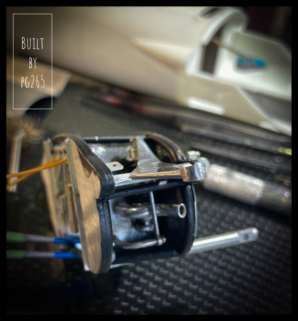
I made the connector that supplies the rear brake and clutch master cylinders by soldering copper wire.
It's easier for the front brakes.
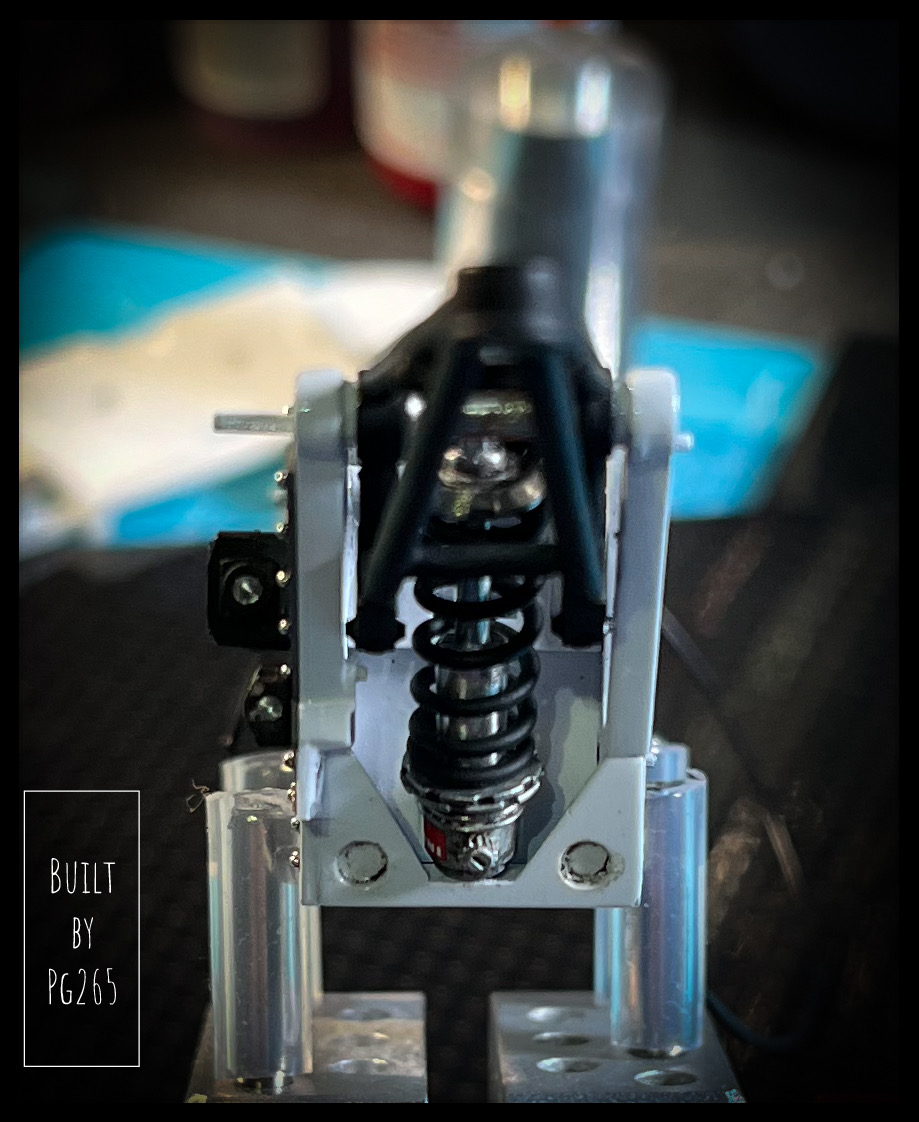
Shock absorbers are installed.
The springs are painted black, but they are a bit short…and very stiff to stretch them!
So I quickly turned shims 6.2mm in diameter for 0.5 in thickness: impeccable! (Perfect)
The front box is gradually being completed.
First, the small tank that comes in the kit needed a bit of work.
I started to take care of him, but was not satisfied with what I would obtain… I made a new one.
It is turned in a log of 2024 (…) detailed with strips of Speed tape and equipped with a brass tenon also taken out of the lathe.
The front bulkhead is riveted.
Next soon.
Pascal🤠-
1
-
-
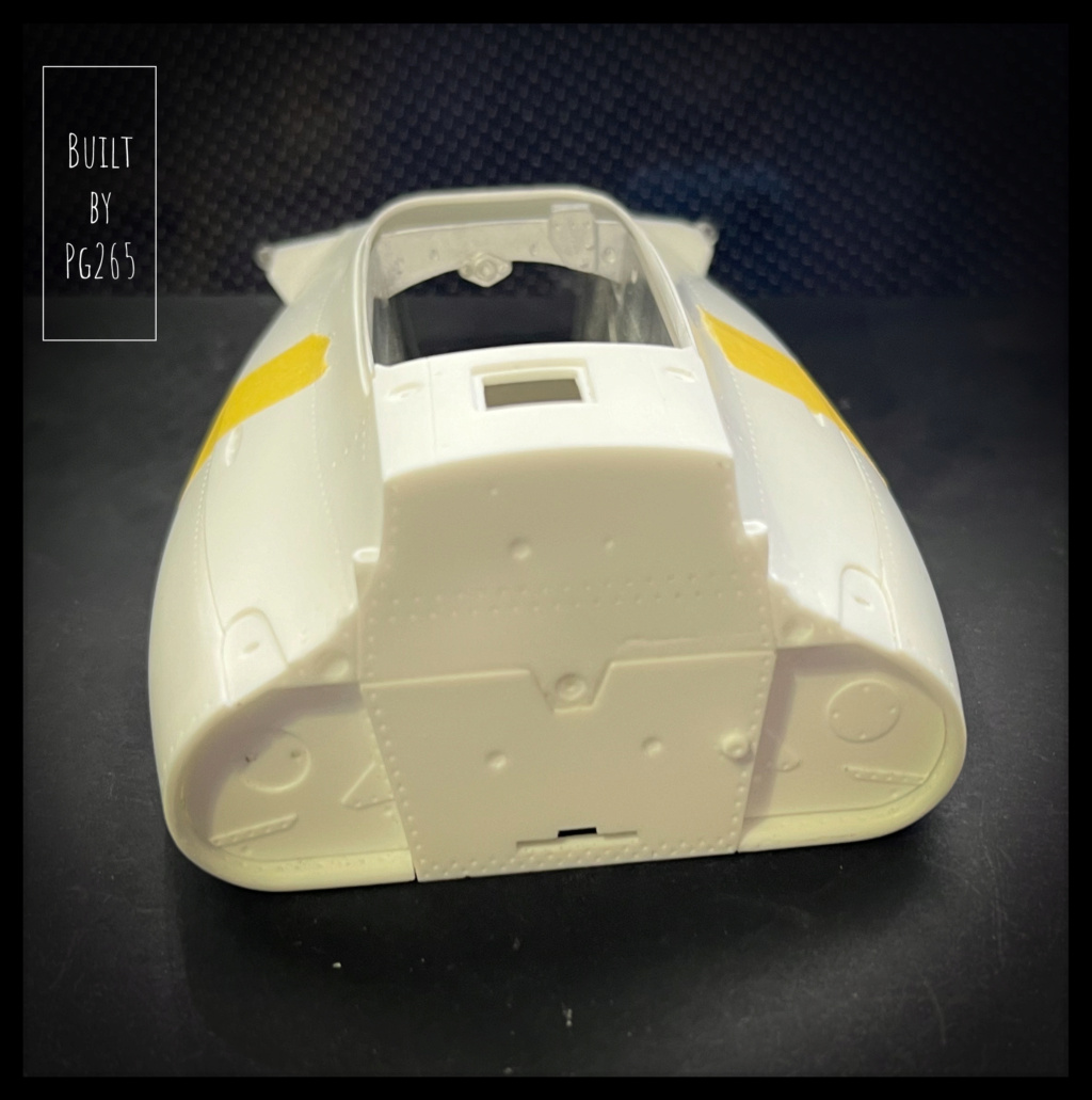
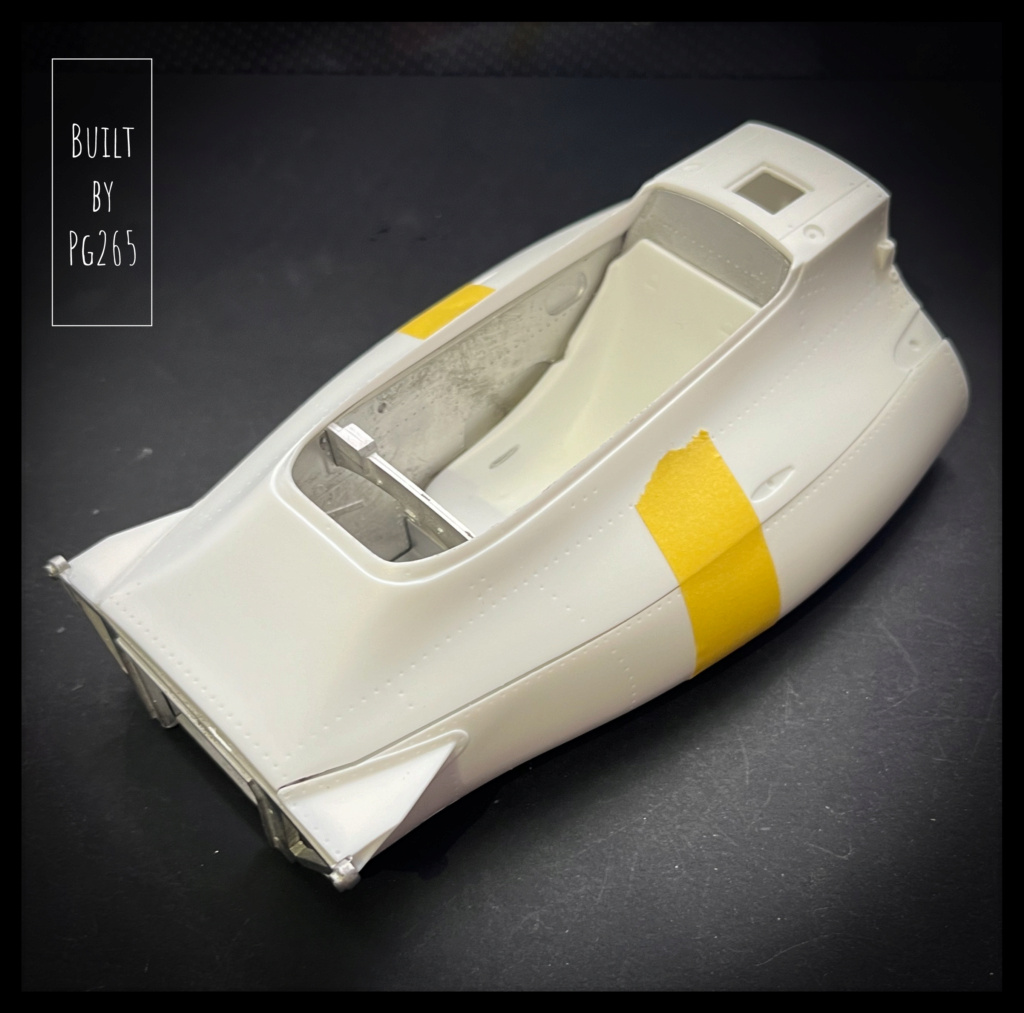
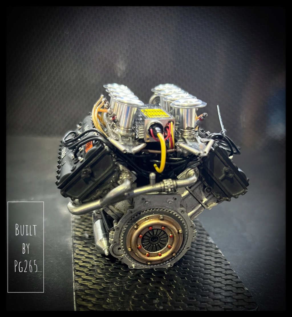
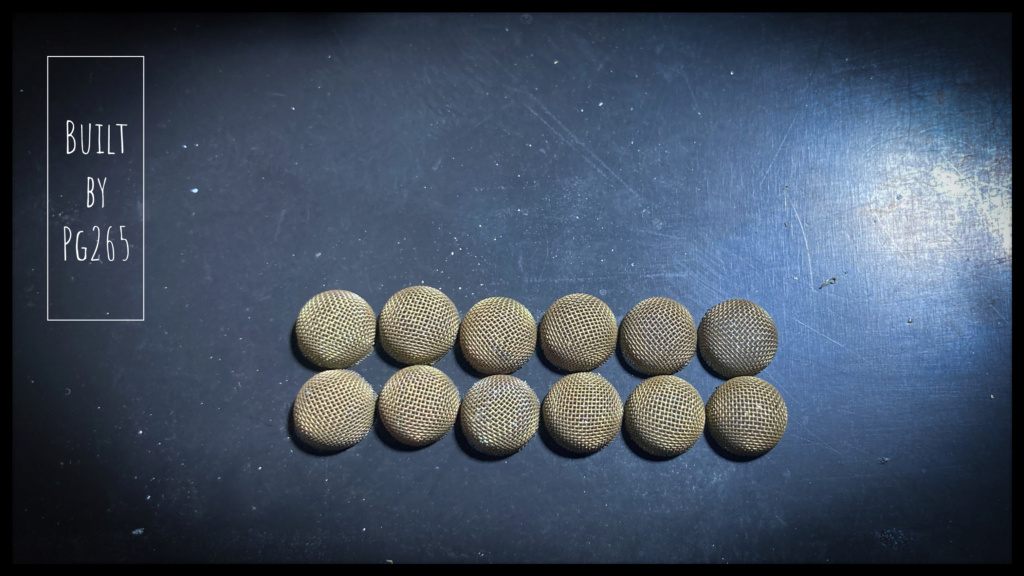
Good evening,
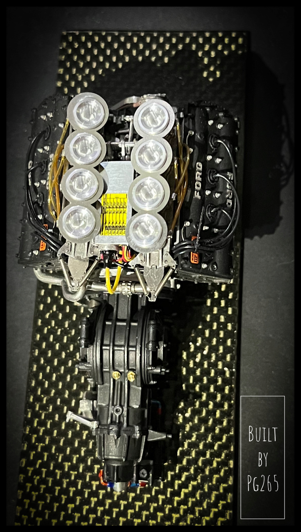
Well, that's it, we now have 12 intake mesh!
The engine is almost finished, it is necessary to take care of the front.
The parts are prepared and test fitted to make sure that there are no anomalies.
Masks are made and identified: the chassis frame was painted black and the aluminum sheets riveted on it.
Then we weld the front partition for more solidity and a better visual aspect in the continuity/junction of the tubes.The assembly is again tested in its location to validate a final installation without problem.
The seat, the dashboard, the arch and the support of the rear fins do not seem to be a problem either.
More soon.Pascal


McLaren M19A, Denny Hulme, 1972 South Africa GP. MFH, 1/12.
in WIP: Other Racing: Road Racing, Land Speed Racers
Posted
Good evening everyone,


Thank you so much!
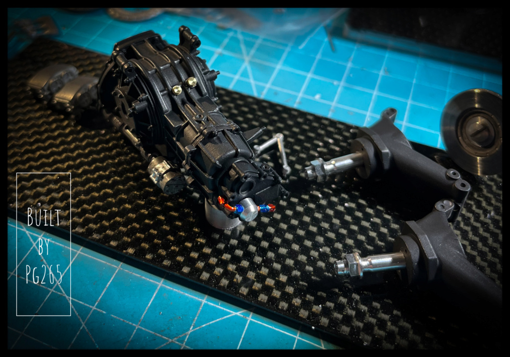
The build continues peacefully, slowly, much more than I would like...
The two front half axles are almost finished, the brake connections are installed and the calipers are just waiting for their bleeding.
The steering bellows will be painted later, the discs patinated to follow.
The front rims are finished, balanced, center polished.
I preferred machined valves to those from the kit.
One of the tires is mounted on the other rim. It is lightly sanded and will be detailed soon.
And here is the wheel shown on its half train.
I was also finally able to complete the rear calipers by fitting them with the missing bleeds.

The engine should cool much better: The braided hoses connect the tank to the oil radiators.
The whole thing will of course be connected to the engine a bit later.
More soon.
Pascal