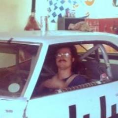
ibj40 Posted September 18, 2018 Share Posted September 18, 2018 (edited) Taking an inspiration from Gene Felton's efforts in road racing in his 1969 Camaro. In the rough and tumble early years of "run-whatcha-brung" IMSA road racing, Felton stuffed a Big Block Chevy engine into it, with moderate success. Taking that concept to the workbench, here are the early results. 1/18 scale GMP Streetfighter body and chassis, and some custom 3D-printed Corvette wide-body fender flares. Putting a Big Block from a Carousel 1 L88 Corvette, with crossflow 4x2 Webers (I think from a GMP Lola). Quick Change rear end from a GMP Winged Sprinter, which will require a custom drive shaft (details on that later). Wheels and tires from a GMP Can Am McLaren, as well. Going to be an interesting build to get the wheels and tires to mount, but I think I have that already figured out, just waiting for some parts to arrive. Stay Tuned! Edited December 6, 2018 by ibj40 Quote Link to comment Share on other sites More sharing options...
randyc Posted September 19, 2018 Share Posted September 19, 2018 Nice! Keep it coming. Quote Link to comment Share on other sites More sharing options...
ibj40 Posted September 20, 2018 Author Share Posted September 20, 2018 Made some progress on fabricating the driveshaft.Took delivery of several sizes of aluminum and brass tubing.Measured the OD of the original driveshaft, and the ID of what appeared to be the most appropriately sized tubing. In this case, a brass thin wall.ID needs to be 5/32, so I chucked the front and rear u-joints up in my "lathe", and dispatched the appropriate machine tool.And now here's the front and rear, ready, and then jointed with the brass tubing.Attaching the wheels to the front and rear axles next. Quote Link to comment Share on other sites More sharing options...
ibj40 Posted September 22, 2018 Author Share Posted September 22, 2018 (edited) Okay, got into fabricating the front axles with which I will be widening the track to get the tire out to the edge of the flare. So, this is the stock stub axle coming off the upright. Remember we are trying to accomplish two things here, widen the track, and locate a set of non-standard wheels onto the model. I am going to create a two piece apparatus. One to fit over the stub axle. The other to fit into the wheel (although I did drill out the wheel to allow this piece of tubing to fit inside the stub axle piece. The wheel adapter is about the same length as the stub axle adapter, owing to the amount pressed into the wheel being about the same length as the stub axle. Going to run a screw down through the center of the wheel into the original plastic stub axle, so that the wheels will roll. Next, moving back to the rears. Here's a teaser. Edited October 6, 2018 by ibj40 Quote Link to comment Share on other sites More sharing options...
ibj40 Posted September 29, 2018 Author Share Posted September 29, 2018 So, working up a fuel filler set up. Many of the 1/18 scale GMP 60's Trans Am Camaro models have a quick fill device in the middle of the rear deck lid.Here's one, for example.The GMP Street Fighter Camaro body donor for this custom didn't have the deck lid cut-out, so I thought I would create a filler similar to the one on my first '69 Camaro racer. Picture's a little grainy but I think you can make it out.Here's a picture of that same rear spoiler, now painted flat black, hanging in my garage/workshop.I took the fuel cell body, and added a center section (resin cast by Mike Kotwick - Swede70).Fabricated a neck out of aluminum tubing, and added a flip-type fuel filler cap (attached it to a smaller piece of aluminum tubing for ease of installation and positioning).Then took a Dremel to the deck lid until I had enough clearance for it to sit flush.Might shorten up the neck just a bit when everything is final, but right now, we've got it pretty much roughed in. Also need to add a vent, pondering a combination of aluminum tubing and shrink wrap (like I used on my custom dump cans). Quote Link to comment Share on other sites More sharing options...
ibj40 Posted October 2, 2018 Author Share Posted October 2, 2018 Clearly this was going to be a problem.So, while waiting for the new bodywork to show up, I have moved the engine back about .25" (in reality, which would equate to about 4.5 inches in the real world).Re-established the front mounting point for the engine, and very glad I had not glued the custom driveshaft together yet.Had to cut some firewall and transmission hump for clearance, which will require some cosmetic fabrication, but did manage to improve front/rear weight distribution.Played around a little more with the fuel filler, more pictures tomorrow. Quote Link to comment Share on other sites More sharing options...
ibj40 Posted October 4, 2018 Author Share Posted October 4, 2018 Not sure how clear these pictures will be, but I found another fuel filler cap (in a lot better condition, and made of chrome-plated diecast in lieu of plastic).This picture, more or less, tells the story.From left to right, original cap, original adapter, original ID of fueling tube, sourced brass tubing, revised ID of fueling tube (with brass insert), and new cap.The new cap fits perfectly into the brass tubing, and with a heavy duty pin vice, I "drilled" out the fueling tube to accommodate a brass insert.Here's the two, more or less, side by side (old on the left, new on the right).I think it makes for a better looking detail.Still waiting on the new flares, so started working on repairing the firewall after I moved the engine back. Might have some pictures tomorrow. Quote Link to comment Share on other sites More sharing options...
ibj40 Posted October 6, 2018 Author Share Posted October 6, 2018 Now,the firewall.This is what a stock GMP Trans Am Camaro firewall looks like. This what it looks like when you put a Big Block in the engine compartment and then move it back a scale 4.5 inches.I had to cut it in the middle to allow a more simple means of grinding away the plastic. I knew that the middle was going to get really thin, and wanted a controlled cut, versus a jagged break. The problem, then, is how do you reconnect the two sides, and then also, how do you seal the hole.I decided I would use a technique that I developed when building my custom race trailer, so I got some 1/8 inch square styrene shape, and formed a channel using a Dremel plastic cutting blade. I then Superglued that piece across the top of the firewall.And now the fun part. How do you fill in that hole, but also making sure that you don't impose into the passenger compartment and interfere with little things like the driver. I decided that I would try to create the new infill by laying in JB Weld, knowing that it will adhere to the plastic of the original firewall (but also knowing that it will take quite a bit of grinding to smooth it up). Test fit of the body to make sure it will all work. And ready for the JB Weld. Quote Link to comment Share on other sites More sharing options...
ibj40 Posted October 7, 2018 Author Share Posted October 7, 2018 The BLOB!And now the grinding starts. Quote Link to comment Share on other sites More sharing options...
ibj40 Posted October 10, 2018 Author Share Posted October 10, 2018 Okay, so back in the day, when I was working on real racers, one of the things we had to focus on was getting water to and from the engine and radiator. On my first racer, a converted '69 Z28 Camaro, running a stock radiator and engine, it was easy. You just had to go down to the local car parts store, buy upper and lower hoses and you were done.As we got into semi-tube frame, and tube frame, things got a little more difficult. Our second racer was a C3 Corvette, on a semi-tube frame (front clip was stock, rear clip was fabricated to hold a Franklin Quickchange center section with a coil-over suspension). When we got it, it was set up for a Small Block Chevy engine, with the radiator in the stock location. Well, in order to improve cooling and air flow, we decided that we would lean the top of the radiator forward, in lieu of how the stock configuration was, therefore setting up the challenge.Once we got the aftermarket radiator located, we then set about trying to figure out the best routing for the hoses. Clearly, stock hoses weren't going to work, so what we did was eyeball the route, and sketch up a solution. I had a buddy who's Dad ran a couple of car parts places, so once we had a design in our head, I'd go over and stand in front of a wall of hoses, and do "research". The conclusion to that process is the inspiration to a solution for this model.First, I knew that the hoses from the Carousel 1 Big Block weren't going to be a direct match to the GMP Camaro radiator, but then moving the engine back a scaled 4.5 inches added a degree of difficulty.Here's how they sit.And here's the solution, again, straight from my racing days. On the racing Corvette, we decided that we would fabricate two aluminum tubes, and connect them to the radiator and engine with very short pieces of hose. In that case (as opposed to what I have fabricated for this model), we welded a bead around each end of the aluminum tube to give the hose clamps something to capture. As you can see here, I have captured the hose inside the piece of aluminum, but I am using a fabricator's license to say that's okay for this model.Hard to see the lower hose, but it's there, and connected. These are just on there loose for now, as there is still a lot of detailing to be completed before final assembly.While I was in the shop last night, I also shortened the drive shaft brass tube, so that it is now the correct length.Worked some on the Blob, and still not satisfied with that solution, and the new bodywork came in, but not enough time to fab it up onto the Camaro body and take pictures (plus, I had to break away frequently to watch the Red Sox/Yankees game). Quote Link to comment Share on other sites More sharing options...
ibj40 Posted October 13, 2018 Author Share Posted October 13, 2018 To misquote an oft-used line from the Old West: Meanwhile, back at the firewall.Clearly, the Blob was not going to be a workable solution. While it was fun, it did not prove to be functional,So, back the the drawing board, or in this case, the cardboard.I took a piece of cardstock and started cutting away everything that didn't look like a firewall. After a few starts and stops, here's where we ended up. This is what a stock, unadultered firewall looks like.This is two GMP Camaro chassis, side by side, just to show how far back the new one has to be to clear the relocated Big Block engine (the piece of styrene is just there as a point of reference). I will use this pattern to produce a new firewall out of styrene sheet, which will be this weekend's fun and games. Quote Link to comment Share on other sites More sharing options...
ibj40 Posted October 13, 2018 Author Share Posted October 13, 2018 New bodywork came in, and I fooled around with some test fitting. Remember, these were intended to fit to a 1/18 scale Carousel 1 Corvette, so some modification will be required for a final.This is with the body sitting on a stock chassis, with standard width wheels and tires. This is with the wider wheels and tires , loosely fit under the final chassis.Now here are some other profile shots. Going to be an interesting process getting the flares to blend into the Camaro bodylines (and I also have a Vega sitting in the wings, for a similar exercise). Quote Link to comment Share on other sites More sharing options...
ibj40 Posted October 28, 2018 Author Share Posted October 28, 2018 Can't believe it has been over two weeks since I updated this thread, but this has been a back and forth project.First off, the firewall has been all consuming, and still not resolved.This didn't work.Essentially, I created an upper profile to match the original position, which proved to be an inaccurate premise, as you can see from these pictures. The front white piece is my initial cardstock pattern, the rearward plastic piece is where my custom firewall eventually ended up.So with quite a bit of "hammer to fit, paint to match" technology, adapted from my years of racing big iron in the Sports Car Club of America GT1 class, we ended up here.Clearly, as you add on the various elements involved in a firewall, such as pedal assembly, steering column, master cylinders, etc., a flat piece of styrene doesn't seem to have much left.But still plenty of work to do. Here's the body "kit".That will eventually house all of this (and more).There's another stock firewall on the way from my good friend Mike Kotwick (swede70), so I decided to turn my attention to the bodywork.To get to this point, there were only three cuts to each front flare, nothing changed on the rear (and remember, these are designed to go on a Corvette).Actually pretty pleased with the initial fitment, now I am considering how to attach 3D printed plastic to diecast metal.Due to the technique I am using to create the rear axle (a piece of brass tubing as the axle housing, with a piece of aluminum tubing as the axle), I can control the rear track and bring the tops of the tire back inside of the fender flare opening.Been working on a couple of other systems, such as the oil cooler/oil filter/oil system connection to the block; as well as the rear suspension (going to raise the rear ride height to clear the fender openings).Might be able to post some photos of that later this weekend. Quote Link to comment Share on other sites More sharing options...
randyc Posted October 29, 2018 Share Posted October 29, 2018 WoW! Just wow. I'm really liking this project. Quote Link to comment Share on other sites More sharing options...
ibj40 Posted November 1, 2018 Author Share Posted November 1, 2018 A couple of previously announced modifications, and then a stream of consciousness moment while I am awaiting the replacement stock firewall from Swede70.First, raising the rear ride height. These are pictures of the "stock" rear suspension of a GMP Camaro (sorry you can't see all the detail, but didn't want to risk removing the wheels). To raise the rear ride height, I cut the shocks in the middle, and will add an aluminum tube center section, and then will raise the rear attachment point by fabricating an aluminum tube extension. Will need to also fabricate an extension for the sway bar arms.Pretty straight forward fabrication.Next, I'll turn to the oil cooling/filtering system.First, we're going to put a larger than stock oil cooler in the front (which will be fed air from a combination of stock radiator opening and removal of the left side headlight blanking plate), since the original setup was designed for a Small Block, and we're running a Big Block. Then we'll mount a remote filter on the radiator/front chassis frame. The oil lines will run to an adapter which is installed in the place of the stock oil filter location. Final assembly will see oil lines run to and from the adapter through the remote oil filter and cooler. When we were racing, there was a frequent debate as to whether you filter before or after the cooler, which sometimes was dictated by the ability to efficiently run the lines without interfering with other components. In the case of this model, that is still to be determined as well.So, we're running a Franklin QuickChange rear end, which has limited natural lubricant capacity. Channeling the torque of the Big Block is going to impart a significant heat load, so I decided to install a rear end cooling system.First step was to add a pump to the back of the rear end, run off the input shaft.Now the question of where to mount the cooler, as the underside of a racer can be exposed to any number of hazards. I decided to place the cooler in the interior, with air flow provided by a NACA duct, cut into the floorboard. Fabrication of the mounting of the NACA duct will commence shortly. Quote Link to comment Share on other sites More sharing options...
ibj40 Posted November 2, 2018 Author Share Posted November 2, 2018 Lots going on in this photo, had a few minutes to kill today, so took tools in hand.Diane and I are heading out tomorrow for our semi-annual vacation to pursue my other hobby love: Scuba Diving. We'll be in Cabo San Lucas for the next seven or so days.That should give you a chance to ponder my next step(s). One hint, the package from Swede70 showed up today. Quote Link to comment Share on other sites More sharing options...
ibj40 Posted November 12, 2018 Author Share Posted November 12, 2018 So back from a great dive trip, and trying to multi-task.The one downside to diving (and I'm not sure I really consider it a downside) is that if you own your own gear, when you get back, you have to clean it and put it away. Salt water does really bad things to poorly maintained dive gear, so a good, thorough clean water rinse is an absolute necessity.Of course, after you rinse, you need to let dry, which results in long periods of nothing to do.Sorry about not having any in progress shots, but once I got back, I plugged the voids between the NACA duct and the chassis floor with body filler putty (took a couple of passed, both above and below), and the employed a partial application of SCCA GT1 racing: "Hammer to Fit, Paint to Match". All in all, pretty pleased with the installation. Yes, I do realize that the paint I am using doesn't match the rest of the interior, but it's a race car.In order to complete the installation, I had to finish the rear suspension fabrication.I measured the outside of the roughed-in rear fender flares, in order to get the axle tube and shaft dimensions correct. Determined that I needed to get the rear suspension more or less finished in order to make the hose run from the pump on the back of the Quick Change rear end to the cooler and back.This is another one of those situations where, if this were a 1:1, we'd be bolting and unbolting components, having them loosely fit, measuring twice, and cutting once. In diecast world, with fat fingers, and only two hands, it means hoping that everything is going to line up, and hitting it with a dab of SuperGlue.As noted above, when I raised the rear ride height, I need to extend both the shocks and the sway bar arms.A combination of brass and aluminum tubing did the trick.Getting the rear end centered in the chassis meant measuring the length of the axle tube (which had been adjusted for the correct rear track), thickness of the Quick Change, measuring the distance from the Quick Change to the spring perches, making sure the pinion angle was correct so that the custom made drive shaft lined up, and then crossing my fingers as the Super Glue set up. As you can see, the rear suspension is still in mock-up stage, and nothing permanent has been attached to the car.Once that was all worked out, I could a approximate the hose runs. I'll make some form of attachment to the chassis as we get closer to final.Still some final detailing, but feeling good about the progress to date. Quote Link to comment Share on other sites More sharing options...
swede70 Posted November 12, 2018 Share Posted November 12, 2018 Looking good - very daring. Thanks for sharing your unfolding updates... Mike K. Quote Link to comment Share on other sites More sharing options...
ibj40 Posted November 27, 2018 Author Share Posted November 27, 2018 Houston, We have a Roller!First, let's start by restating the problem.There's a big hole that needs to be closed between the engine compartment and the interior of the car.Several abortive attempts have been chronicled here, among others that fell by the wayside undocumented.What you see here is version four of a several hour session of cardboard templates, styrene sheet, heavy duty scissors, and Dremel sanding bits.May not look like much, but it solves the problem. Essentially, the top level matches up to a stock firewall that I relocated back far enough to clear the distributor cap on the Big Block. Hard to see in this picture, but you will just have to trust me on this one. With that problem solved, I went ahead and mocked up the rolling chassis (still not glue worthy as a final just yet).In order to simplify final installation, I cut the stock steering column, and then will splice it with a piece of stainless tubing. For some reason, the stock chassis had an indention for a cross member, right under where the new pedal location will be, so I had to remove that, which required that I also cut a little bit into the transmission tunnel. You can see the companion location in the passenger compartment.Crossmember won't be reinstalled anyway, as the transmission is in the way. To reinforce the floor, we're going to install some diamond plate under the driver's feet (on our '86-bodied Trans Am spec tube frame Camaro, we actually installed a sandwich of 1/8 inch aluminum on top - 1/8 inch steel on the bottom, with a foam insert under the driver's feet). Mocked up the radiator and oil filter and oil cooler, still need to run the lines back to the block. The cooler will sit flat once everything is ready to be bolted together for the last time. Taking the body to be dipped later this week, and will be able to focus on a permanent mounting solution for the flares. Weather turned cold here in Texas over the weekend, and with an unheated shop, not sure how much more progress I will be able to make. Quote Link to comment Share on other sites More sharing options...
Anglia105E Posted November 29, 2018 Share Posted November 29, 2018 Well I must say Jim, this is one hell of an almighty project....... and your build skills are something to admire. While following your explanation and studying the photos, I have to keep reminding myself that this is 1:18 scale you are working in. This sort of detail would be typical of a 1:12 build I reckon, and obviously a lot easier in 1:8 scale Pocher type kits. Myself, I like the whole concept of modifying diecast scale model cars, which I have done with a 1:24 scale Franklin Mint Rolls-Royce 1929 Phantom I Cabriolet de Ville, converting the standard car into the 1927 version as owned by Fred Astaire. Currently I am building a ' hybrid ' Rolls-Royce Silver Cloud II from a plastic chassis Revell or Minicraft kit and a diecast Franklin Mint 1955 Silver Cloud, which involves changing the 4.9 litre 6 cylinder engine to the 6.2 litre V8 engine. Keep us up to date with your progress, which I am following closely. David Watson ( England ) Quote Link to comment Share on other sites More sharing options...
MeatMan Posted November 29, 2018 Share Posted November 29, 2018 Very nice work, no matter the scale! Quote Link to comment Share on other sites More sharing options...
ibj40 Posted December 6, 2018 Author Share Posted December 6, 2018 Okay, got the body back late yesterday, and had to play around with it, although the cold and wet weather we are having played havoc with the SuperGlue I used to attempt a temporary bonding. Clearly, this is going to require a lot of work to feather the edges of the 3D printed flares, but thought without the original red paint of the donor body that these appear a little more representative.Got me a little bit of BMW Batmobile going on here at the back! Quote Link to comment Share on other sites More sharing options...
randyc Posted December 11, 2018 Share Posted December 11, 2018 UGh! LOL Lots of work. I lose interest too quick these days. But I am thoroughly enjoying watching this car get transformed. Randy Quote Link to comment Share on other sites More sharing options...
ibj40 Posted December 12, 2018 Author Share Posted December 12, 2018 7 hours ago, randyc said: UGh! LOL Lots of work. I lose interest too quick these days. But I am thoroughly enjoying watching this car get transformed. Randy I know what you mean, I'll get really excited, and go hot and heavy, and then reach an impasse, and just let it sit for a while. Can only keep about three models going at the same time, due to workbench space, so always hope another one keeps me inspired. Thanks for the compliments, everyone. That really helps. Quote Link to comment Share on other sites More sharing options...
ibj40 Posted August 7, 2019 Author Share Posted August 7, 2019 Been a while since I visited this build, but acquired some parts, and thought I'd at least update my pictures. My good friend, Mike Kotwick (Swede70 on many of the boards) is a master at resin casting, and he took an idea I had about extending GMP Trans Am Camaro front spoilers to heart, and nailed it. Along the way I also acquired a "fibreglass" high hood scoop hood, which will be perfect for feeding more air to those hungry Webers perched on top of the Big Block Chevy. This one will probably go back on the shelf until after the Petty Belvedere is done, but though an update might be appropriate. Enjoy! Old stock front spoiler for comparison. And now the updates. Quote Link to comment Share on other sites More sharing options...
Recommended Posts
Join the conversation
You can post now and register later. If you have an account, sign in now to post with your account.
Note: Your post will require moderator approval before it will be visible.