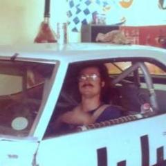
ibj40 Posted July 13, 2019 Share Posted July 13, 2019 Once again, working in 1/18 scale, trying to create models that never existed in this scale, and probably never will. Here are the donors: Body from Highway 61, chassis from Winged Warriors. Chassis To create this: Lots of fabrication that I am not going to bore you with, but had a breakthrough moment over the past couple of days that I wanted to share. Among the issues, was that the original front cage hoop interfered with the front radiator bulkhead of the Belvedere, so I cut some of the diecast to get it to fit. But as I got deeper into the build, it was clear that I needed to replace the pieces of the bulkhead in order to have a "complete" chassis, so I used styrene angle to fabricate and top and bottom for the radiator opening. Still had to cut the roll cage pieces, and will need to meld them eventually as I get closer to completion. Plus, with the differences, I had to insert a piece of brass channel to fill the gap for the front roll cage supports. One other element that I didn't find on 1/24 scale plastic versions of this model was the vestigial rear spoiler. As you can see in the second, black and white photo, there was clearly a piece of aluminum (from my experience) angle riveted to the trunk. I duplicated that with brass angle. Clearly it was painted body color, so I did some primer testing tonight, to see what it looked like. I think I have the rake of the body and the chassis pretty close. Still to go: firewall and dash, rear package tray, fuel cell mounted into trunk, and detailing. Quote Link to comment Share on other sites More sharing options...
swede70 Posted July 13, 2019 Share Posted July 13, 2019 It's looking very good thus far. Thanks for sharing... Mike K./Swede70 Quote Link to comment Share on other sites More sharing options...
randyc Posted July 14, 2019 Share Posted July 14, 2019 You do some great work! Quote Link to comment Share on other sites More sharing options...
ibj40 Posted July 15, 2019 Author Share Posted July 15, 2019 So here's the dilemma; you got two models, and they each have a component that serves a specific purpose, but they aren't exactly identical, so you have to either make a choice or dig really deep into fabrication. Firewall (already sanded vacuum lines, wiper motor, etc. off the Belvedere version) Where the firewall goes. Dashboard Package Tray Where the Package Tray goes. One admission of guilt: Belvedere package tray has already been removed from Belvedere trunk to allow this modification to proceed. Like Arnold said in the Terminator: I'll be back!" Quote Link to comment Share on other sites More sharing options...
vintagercr Posted July 18, 2019 Share Posted July 18, 2019 Coming along nicely Quote Link to comment Share on other sites More sharing options...
ibj40 Posted July 22, 2019 Author Share Posted July 22, 2019 (edited) Made some progress over the weekend. Let's start with the firewall. Here are the two pieces, one from the Belvedere, the other from the Superbird. The issue is to fill in the gaps and make them fit the other model, where appropriate. The Belvedere firewall interfered with the Superbird chassis, so I had to trim some at the bottom. I use a nipper that we used back when I was building race cars, as it has a very sharp bite, and takes a small 1/4 x 1/16 piece with each application. And the revised piece looks like this. When applied back into place, we end up with a gap between the Belvedere firewall and the ends of the rollcage tubes in the engine compartment. I took the Superbird firewall and removed the ends (not a lot of detail to it to begin with) where the rollcage formerly matched up in the Superbird. I installed them onto the ends of the rollcage, and then when I inserted the Belvedere firewall, they close up the gap nicely. I'll chamfer the square edges so that the transition between the pieces isn't so abrupt, and then when it is all painted the same color, I think it makes a nice solution. Next, I attacked the dash, again with two pieces to choose from. Didn't take a lot of progress shots, but since the Belvedere dash will bolt nicely into the Belvedere body, but the Superbird dash, rudimentary as it is, looks kinda "racy", I just ground away the non-essential parts of both. And will put them together. Again, paint will help a lot to cover up some of the crudeness. One thing I did notice as I was closing up shop last night is that the Belvedere dash interferes with the A-posts of the Superbird cage, but a little bit of Dr. Dremel will cure that. Rear package tray and trunk/fuel cell are next. Edited July 22, 2019 by ibj40 Quote Link to comment Share on other sites More sharing options...
zakdoggi Posted July 23, 2019 Share Posted July 23, 2019 Nice build. I like the way you're going about it. I'll be watching. Quote Link to comment Share on other sites More sharing options...
ibj40 Posted July 23, 2019 Author Share Posted July 23, 2019 So, I think I had a successful date with Dr. Dremel last night, although it was a lot more involved than simply grinding away some plastic. First, I needed to take everything apart, starting with the dash, so that I could also remove the windshield (so as not to scratch it) to mark the apparent obstruction. And then put the dashboard back in and get a reference line drawn. And then grind away, and refit. There were several iterations, each one requiring the dashboard to be removed and then reinstalled. And then full reassembly. From the side Before Surgery Post Surgery And while working with the body last night, I decided that the plastic angle I used to replace the front bulkhead isn't substantial enough, so I ordered some brass angle to replace it. These two pieces will be recut from the brass angle and then re-primed. Quote Link to comment Share on other sites More sharing options...
ibj40 Posted July 28, 2019 Author Share Posted July 28, 2019 Update on the dashboard project. Dr. Dremel and I may have been a little too enthusiastic in search of a cure for clearance, so a little bit of cosmetic surgery is called for. Got out my trusty tube of body filler, and some blue masking tape. First pass taught me some lessons, so I ground away most of what I didn't like, and went at it again. This is currently curing on my workbench, not sure I will be able to do much for a few days. Brass angle arrived yesterday, as well, and still thinking about the means to duplicate the two plastic angle pieces. Quote Link to comment Share on other sites More sharing options...
ibj40 Posted August 5, 2019 Author Share Posted August 5, 2019 Okay, well on to Plan B. One of my favorite substances for modeling is JB Weld, just like Frank's Red Hot Sauce, I'd put that s**t on anything. So, with these gaps to fill. Over the weekend, I finally produced this. And don't worry, I had the rollcage bars wrapped in blue masking tape, so this is the end product. Had the dashboard in and out so many times I was dreaming about it. There are about four layers of JB Weld, as I started with a layer on the top, took the dashboard out, lay in a layer on the bottom, and then did that same process one more time. Along the way, I filled in the holes in the hood where the original hood scoops on the donor model were, as well as where the hood ornament was. Threw some primer at the hood just to see how I did. Still a little rough, but when I send the body off to the guy who strips the paint for me, it should clean up just fine with a little bit of sanding. Roughed in the front and rear bumpers, just to get an idea about the final. I'm pretty pleased with where we are, and just need a few more details taken care of. Quote Link to comment Share on other sites More sharing options...
Gramps46 Posted August 6, 2019 Share Posted August 6, 2019 Coming along nicely. Please keep us posted. Quote Link to comment Share on other sites More sharing options...
ibj40 Posted August 23, 2019 Author Share Posted August 23, 2019 It is hot down here in Texas these days, which restricts my working from my non-air conditioned garage workspace, but I've been trying to make progress when I can. One of the issues I had pointed out previously is the rake of the body on the chassis, and how it didn't appear right. Here's where we were and clearly the rear of the car is way too low. This is what a real one looked like on the track. You can clearly see that back in the day, these cars used rear leaf springs, and one of the ways to change the rear ride height was to install a spring shackle in the rear where it mounted to the chassis. With multiple holes in the aftermarket shackle, you could adjust the ride height to suit the track. The other way (and frequently used in combination with the shackle) was a lowering block between the leaf spring and the axle mounting point. Well with diecast, and how the diecast and plastic pieces are created, neither of these methods is available. For this chassis, the rear axle assembly is firmly mounted to the chassis with two screws. So what I have done is built spacers out of brass and aluminum tubing to replicate the effect of lowering blocks. Which required acquiring longer screws than those which located the rear axle in the original location. I experimented with a couple of different heights of my "lowering" blocks, but think I may have nailed the rake pretty closely (although I'm still not fully comfortable with the front). You can see, however, that now the rear of the model's leaf springs don't match up with the model's chassis. To cure that, I will actually build my own "shackles" out of Styrene rectangular rod, and drill down through them all to make it all fit. Quote Link to comment Share on other sites More sharing options...
randyc Posted August 23, 2019 Share Posted August 23, 2019 Looking at the photo of Petty's car and the diecast body, the Petty car's rear wheel openings are higher in the body than the diecast body. The real car is more like the diecast. In my world, that is impossible to fix in the model. That may be contributing to the appearance that the diecast rake is off? Either way, I am enjoying watching the build up. Quote Link to comment Share on other sites More sharing options...
ibj40 Posted August 24, 2019 Author Share Posted August 24, 2019 7 hours ago, randyc said: Looking at the photo of Petty's car and the diecast body, the Petty car's rear wheel openings are higher in the body than the diecast body. The real car is more like the diecast. In my world, that is impossible to fix in the model. That may be contributing to the appearance that the diecast rake is off? Either way, I am enjoying watching the build up. Classic problem with working in diecast. Sometimes you have to squint your eyes and pretend. Did some more tonight, will post up some weekend shots later. Thanks! Quote Link to comment Share on other sites More sharing options...
Gramps46 Posted August 24, 2019 Share Posted August 24, 2019 Thanks for the update and sharing your progress. Quote Link to comment Share on other sites More sharing options...
ibj40 Posted August 24, 2019 Author Share Posted August 24, 2019 One other area that needed attention was the trunk and the fuel cell filler and vent. This is the top of the fuel cell from the Hamilton donor in the trunk of the Belvedere. Clearly I need to get from the end of the black hose through the trunk and left rear fender. Initially I considered just a scabbed piece to close the internal gap. That would be a cop-out, as I have this nicely defined port on the left rear fender. So I drilled all the way through the bodywork, and the trunk. Created a longer transition piece out of thin wall aluminum tubing that picks up the black plastic hose to the fuel cell. And then finished it all out with a vent tube from the top of the fuel cell, routed to an outlet in the left rear taillight. Quote Link to comment Share on other sites More sharing options...
ibj40 Posted August 25, 2019 Author Share Posted August 25, 2019 Got the spring shackles fabricated, 1/8" x 3/16" solid styrene rod, cut 1/4 inch long, with a 3/64" hole drilled lengthwise, secured by a 0-80 x 1 inch screw (I ran out of 0-80 nuts, so had to order them) which I will cut down to length. I'll paint the "shackles" black before final fabrication. Wanted to set the body down and check how it looked, but with the fuel cell mocked up in the trunk, the screws are too long and interfere. Hopefully the nuts will show up this week, and I'll able to get this chapter closed. Although, now that I know how to change rear ride height (and rake), I may go back and attack the front. Quote Link to comment Share on other sites More sharing options...
Gramps46 Posted August 26, 2019 Share Posted August 26, 2019 Good looking fabrications. Quote Link to comment Share on other sites More sharing options...
ibj40 Posted September 15, 2019 Author Share Posted September 15, 2019 Now, for the weekend update. I'm Chevy Chase, and You're Not! Anyway, been working, off and on, trying to get some details done. Built a package tray out of really thin aluminum sheet. Don't have pictures of the structure underneath required to bring it up to the correct height, but trust me, it was clearly a "Hold My Beer" process. For a reason that defies logic, the steering column of the Superbird was diecast, and damned brittle at that! It shattered into more pieces than I prefer to count, but I was able to salvage the hockey stick that actuates the steering and the plastic steering wheel. I have fabricated a steering column out of brass tubing, along with a collar to match up the steering wheel to the column. Again, didn't take a lot of pictures, but trust me, considerable brass tubing was sacrificed to get to this point. I also needed to relieve the cockpit footwell (which includes the cage from the Superbird), and the firewall (from the Belvedere) in order to get the alignment. And then, re-attaching the firewall, to the Superbird chassis, with the Belvedere firewall to match the body, required some ingenuity. I have become an advocate of using pins to connect pieces (my "pins" are actually pieces of paper clips). Here's how the firewall is attaching. You can see the holes I drilled into the chassis to accept the pins. And here it is, assembled. Quote Link to comment Share on other sites More sharing options...
randyc Posted September 15, 2019 Share Posted September 15, 2019 Wow. I'm impressed with your ingenuity. I'd have committed the whole thing in a box by now. Quote Link to comment Share on other sites More sharing options...
ibj40 Posted September 16, 2019 Author Share Posted September 16, 2019 (edited) Wrapping up the Weekend Update with a lot of progress. Here is a picture of the front of the engine compartment, with the cage tube coming around in front of the radiator, and a piece of brass channel to fill in a gap. Here we are with that fabrication completed. Essentially, I had to take about a 1/4 inch slice out of each horizontal tube, and used my post technique to rejoin them. And then for the chassis attachment, I drilled two holes where the cage mounts meet the frame rails, and then drilled two more smaller holes in the brass channel (now painted gloss black to match the rest of the engine compartment). Ending up with what I feel is a reasonable solution. The bar coming around the front of the radiator is actually critical as it locates the height of the body at the front. Edited September 17, 2019 by ibj40 I can't spell. Quote Link to comment Share on other sites More sharing options...
randyc Posted September 17, 2019 Share Posted September 17, 2019 Nice work. I'm sstill watching this one to see how the story ends. Quote Link to comment Share on other sites More sharing options...
ibj40 Posted September 17, 2019 Author Share Posted September 17, 2019 One other work in progress is the fuel cell/fuel filler set up. As you can see, there is a gaping hole where the stock gas cap used to be. Here's the pieces that need to fit. The outlined piece is actually multiple diameters of different tubing sizes, all cut to the same length, with ends clearanced so that they fit inside each other. This is what I hope to build a realistic looking fuel filler with cap. This is the trunk with the fuel cell and fuel hose mocked up. This is what I did last night while my wife watched this season's premier of Dancing with the Stars. This is the largest diameter aluminum tube, JB Welded in place. I'll clean this all up with a Dremel sanding drum, and get the outside back to the proper body contour, and clean up the inside so that the tube just touches the edge of the trunk. After that, I will start staging the other tubing sizes to create the effect I am looking for. Quote Link to comment Share on other sites More sharing options...
swede70 Posted September 19, 2019 Share Posted September 19, 2019 Looking nice and making good progress. Mike K./Swede70 Quote Link to comment Share on other sites More sharing options...
ibj40 Posted September 19, 2019 Author Share Posted September 19, 2019 Forgot to take a picture of the cleaned up outside, but was so excited about how well it looked I took off on the next step. Here is a picture of the next size smaller tubing (brass in lieu of aluminum) that will be the transition piece to the plastic "fuel hose" attached to the top of the fuel cell. And then, after a lot of trimming, a new longer and radiused brass piece, and some fore and aft shifting of the fuel cell top, here's where we are this morning. The extra brass tubing on the outside of the fender will be ground down flush with the bodywork. One thing to notice is that the rear package tray is not installed (for ease of multiple iterations of body/chassis separation), but that it forms an integral component in body height location, which also influences trunk location. I am hoping that when I do a semi-final dry fit of everything tonight that I'm still close. Quote Link to comment Share on other sites More sharing options...
Recommended Posts
Join the conversation
You can post now and register later. If you have an account, sign in now to post with your account.
Note: Your post will require moderator approval before it will be visible.