my66s55 Posted June 8, 2021 Author Share Posted June 8, 2021 The front clip is next. This first pic is the original. Note the lip around the edge of the part. This lip has to be deleted in order to thicken the part for printing. The middle pic is the part after fixing and eliminating the lip. The third print has the walls thickened and is ready for printing. I have found that 1.7 millilitres is the best thickness for body parts.The reason I use individual parts is that it is the best and easiest way to thicken the car. Quote Link to comment Share on other sites More sharing options...
my66s55 Posted June 10, 2021 Author Share Posted June 10, 2021 The original file was a Coronet. I want to create a Custom Royal Lancer. To do that, I need to make files of the Tail fins, the Custom Royal Lancer name on the front fenders and two chrome strips that go on the rear panel below the trunk lid.Notice the file I used to create the name. 1 Quote Link to comment Share on other sites More sharing options...
my66s55 Posted June 11, 2021 Author Share Posted June 11, 2021 Let's take a look to see what we've accomplished. Then do a quick test print. 1 Quote Link to comment Share on other sites More sharing options...
charlie8575 Posted June 12, 2021 Share Posted June 12, 2021 On 6/6/2021 at 1:09 PM, my66s55 said: Sounds like an interesting proposition Charlie. Please keep me posted as to the details. If you'd like, give me your e-Mail, and we can discuss. Also, I tried to order through Facebook one of your Polyhead A-blocks. If you can e-Mail me the details on how to order, I'd appreciate it. I can use at least two or three of them. Charlie Larkin Quote Link to comment Share on other sites More sharing options...
my66s55 Posted June 12, 2021 Author Share Posted June 12, 2021 5 hours ago, charlie8575 said: If you'd like, give me your e-Mail, and we can discuss. Also, I tried to order through Facebook one of your Polyhead A-blocks. If you can e-Mail me the details on how to order, I'd appreciate it. I can use at least two or three of them. Charlie Larkin crai2773@bellsouth,net. Quote Link to comment Share on other sites More sharing options...
MeatMan Posted June 12, 2021 Share Posted June 12, 2021 19 hours ago, my66s55 said: Let's take a look to see what we've accomplished. Then do a quick test print. Good stuff Doug! What printer are you using? Quote Link to comment Share on other sites More sharing options...
my66s55 Posted June 12, 2021 Author Share Posted June 12, 2021 My next creation is the frame. First I find a frame chart for the convertible and take screen shots of the top and side. These I import into a new Blender file. The top goes into the top view and the side into the appropriate side view. Then they are lined up and the drawing begins. I always start with the top view. It's always important to search for reference pic's. In this case, I found a 55 Plymouth frame for sale that had 13 different views. Plymouth, Dodge same basic frame. Quote Link to comment Share on other sites More sharing options...
my66s55 Posted June 12, 2021 Author Share Posted June 12, 2021 33 minutes ago, MeatMan said: Good stuff Doug! What printer are you using? I will only use Phrozen printers. It's a Taiwan company run by 3 Taiwanese engineers. The printer in this case is the 2018 XL I upgraded it from a 2k rgb lcd to a 4k mono lcd last June. Mono lcds let more light through and cure the resin faster. This speed the print time up by i/3 rd or more. The 57 DeSoto took 15 hrs at 2k and 11 hrs 4k. Quote Link to comment Share on other sites More sharing options...
my66s55 Posted June 14, 2021 Author Share Posted June 14, 2021 Frames done. Next comes the front suspension. Quote Link to comment Share on other sites More sharing options...
Bainford Posted June 14, 2021 Share Posted June 14, 2021 Wow. Some pretty impressive stuff going on here. Quote Link to comment Share on other sites More sharing options...
my66s55 Posted June 15, 2021 Author Share Posted June 15, 2021 I used the service manual to find pics to make the upper and lower control arms. Here are 2 of them. Here's the finished parts. Quote Link to comment Share on other sites More sharing options...
Spex84 Posted June 15, 2021 Share Posted June 15, 2021 Fascinating stuff...I'm impressed by the size of the parts you're able to print! I've also encountered the difficulties of free 3D models being absolutely trash from a geometry perspective. Many of the free models out there were either created many years ago by hobbyists, or stolen from video games and modified over the years for other purposes (sometimes with dubious workmanship). That Dodge mesh has some proportional issues, but at least it looks like it was in the ballpark! I really want to do a Stude pickup, but the time required to model, support, and print the parts is pretty intimidating, especially considering I'd have to print the body in small chunks and then assemble them. Quote Link to comment Share on other sites More sharing options...
my66s55 Posted June 17, 2021 Author Share Posted June 17, 2021 Adding a steering knuckle, shock and coil spring makes the front suspension. Quote Link to comment Share on other sites More sharing options...
misterNNL Posted June 17, 2021 Share Posted June 17, 2021 I admire to bring of the short-sided opinion when 3-d models first started being shown that this not going to work well for finished models. The stuff looked like laminated sheets with rough edges that would takes forever and a day to smooth out. Today's stuff has certainly evolved into some very interesting and very buildable offerings. The language is completely foreign to me so thankfully there are those here who can make it all work.my how things have changed! Quote Link to comment Share on other sites More sharing options...
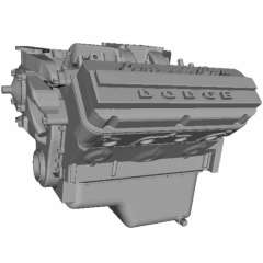
my66s55 Posted June 18, 2021 Author Share Posted June 18, 2021 (edited) So now the body has been corrected. The frame and suspension have been done. I put my 55 Dodge 270 hemi in to help for positioning the next step. Up coming next is under the hood files Edited June 18, 2021 by my66s55 Quote Link to comment Share on other sites More sharing options...
bill-e-boy Posted June 18, 2021 Share Posted June 18, 2021 As an owner of a real deal 56 Dodge CRL coupe you have got the details very accurate. The 55 and 56 chassis were the same but the convertible has an X member for additional strength The front body mount is a U shaped piece welded to the front cross member and does not have a wedge shaped tunnel that carries on to the back of the cross member that is depicted in one of you renderings I have attached an image of that area and of the spring pocket area of the front cross member The front end shown under the Dodge chassis is a Jag XJ6 that I installed in place of the original - a long story that came about but it is on the road now and it is awesome Quote Link to comment Share on other sites More sharing options...
my66s55 Posted June 21, 2021 Author Share Posted June 21, 2021 On 6/18/2021 at 4:25 PM, bill-e-boy said: As an owner of a real deal 56 Dodge CRL coupe you have got the details very accurate. The 55 and 56 chassis were the same but the convertible has an X member for additional strength The front body mount is a U shaped piece welded to the front cross member and does not have a wedge shaped tunnel that carries on to the back of the cross member that is depicted in one of you renderings I have attached an image of that area and of the spring pocket area of the front cross member The front end shown under the Dodge chassis is a Jag XJ6 that I installed in place of the original - a long story that came about but it is on the road now and it is awesome Thanks for the heads up.The bottom pic will help me a lot. Quote Link to comment Share on other sites More sharing options...
my66s55 Posted June 21, 2021 Author Share Posted June 21, 2021 I found a site with a 56 Dodge that was being built for Trans Am racing. There are pics of the sheet metal for under the hood that gave me great insight on how to create the needed parts. This one worked well to make the horse collar. Quote Link to comment Share on other sites More sharing options...
gui_tarzan Posted June 22, 2021 Share Posted June 22, 2021 I think what you're doing is a fantastic thing, but that '64 Buick Skylark convertible is a barrel of errors. I have that one too and I'm just starting to try to figure out how to correct it. There isn't a panel or edge on it that's correct. Quote Link to comment Share on other sites More sharing options...
my66s55 Posted June 22, 2021 Author Share Posted June 22, 2021 1 hour ago, gui_tarzan said: I think what you're doing is a fantastic thing, but that '64 Buick Skylark convertible is a barrel of errors. I have that one too and I'm just starting to try to figure out how to correct it. There isn't a panel or edge on it that's correct. I won't be using that 64 Skylark for my project. I have a raw scan I got off Sketchfab. 1 Quote Link to comment Share on other sites More sharing options...
bisc63 Posted June 22, 2021 Share Posted June 22, 2021 Oh man, I really want a '64 or '65 Buick Skylark model. SUCH a handsome car! I hope you do one... 1 Quote Link to comment Share on other sites More sharing options...
my66s55 Posted June 23, 2021 Author Share Posted June 23, 2021 (edited) Of all the cars I have files for, I don't have one for a 55 Plymouth. I did find a raw scan for a 56 4 dr that I'm using that to create some parts for the 55. This is what I did over the last few days. Take the scan. Cut out that area to make the trunk lid. Trace the needed part. Subdivide it, smooth it and you get this. It's only half,but that's all I need. Thus, you can see how I'll create the above Skylark. Edited June 23, 2021 by my66s55 Quote Link to comment Share on other sites More sharing options...
bill-e-boy Posted June 23, 2021 Share Posted June 23, 2021 Here is a shot of the firewall. The brake booster is a Chebby item and the chassis at this point has been modified for the Jag XJ6 front end And a shot of drivers side chassis with motor in place - not original 315 Poly but an LA360 Quote Link to comment Share on other sites More sharing options...
sbk Posted June 24, 2021 Share Posted June 24, 2021 Nice work! My apologies if you already mentioned it, but what program are you using for design? Thanks, Steve Quote Link to comment Share on other sites More sharing options...
my66s55 Posted June 24, 2021 Author Share Posted June 24, 2021 On 6/23/2021 at 2:37 PM, bill-e-boy said: Here is a shot of the firewall. The brake booster is a Chebby item and the chassis at this point has been modified for the Jag XJ6 front end And a shot of drivers side chassis with motor in place - not original 315 Poly but an LA360 Thank you very much. Any help is graciously appreciated. There isn't enough pics on the internet to fully cover this subject. Quote Link to comment Share on other sites More sharing options...
Recommended Posts
Join the conversation
You can post now and register later. If you have an account, sign in now to post with your account.
Note: Your post will require moderator approval before it will be visible.