Peter Lombardo Posted November 18, 2009 Share Posted November 18, 2009 (edited) This is my next long term project. I plan on taking the new technique I learned, vacuum forming, to the next level. The Art Deco Aero Coupe was a single piece body design. I kept the design more simple since I had no experience with vacuum forming….honestly, I didn’t even know if it would work. What a shock and surprise to me when it worked better than my widest expectations. But that was then and this is now…I must expand my horizons. Ok, in this new era of financially trying times, I figure that the manufacturers will have far less cash laying around for such frivolous things as “Image Enhancing Concept Cars†so I think I should jump in and design and build a concept car for GM. I figure that a new updated concept for the Corvette is long over do so I have taken on the challenge to produce a model of one. I have dubbed my concept the “Corvette XP45C†which stands for eXperimental Prototype 45 inch high Coupe. Ok, maybe that is a little lame and pretentious, but this is my gig and I can do as I see fit. So far, this is just a quick ink rendering of the car along with the main dimensions. I went through a number of ideas, a few with a front engine layout but ultimately settled on the rear engine layout for two reasons. One, I think that is the logical evolution direction for the Corvette platform and two, the current engine and trans-axle when mated up make for a tidy little rear engine combo. The radiator will still be up front, with a hot air exhaust vent on the front hood, ala, Ferrari P330. The body is a little narrower in the mid section with the body work flaring out at the wheel fender covering areas. The design has a full wide track, but the body tapers inward in a subtle F1 race car style. The rear wheel has a “spat†skirt over it because I like the way they look on the Art Deco Coupe I am working on now. There will be no steering wheel in the cockpit, as this car will incorporate the latest “fly by wire†technology. All engine and steering control functions are going to be controlled by a “joy stickâ€. Actually, I think Mercedes just introduced a concept coupe that uses this style of vehicle control management, so I think the technology belongs on a Corvette too. You know, since all the kids today grew up on computer games, autos should evolve too. I have incorporated side scallop indentations behind the front wheels as a small tribute to the early 60’s Vettes. And the two doors will open upward with hinges way up in the front wheel area. What you do not see in these renderings is that I have the rear deck designed low, just over the top of the engine, with a window allowing a viewing access to the engine top, like the new Corvette Z06 showed. The rear sail panels are high but the rear deck is low. I guess I should have done a rendering from that angle also showing the rear panel, exhaust outlets and tail lights. My design has been influenced by many cars and designs that have gone before…a little P330 Ferrari, a little GT40, a little Corvette, a little Star Wars, and a little Cosmic Motors. I love the design work of Galaxion 5000 and the similar designs by Daniel Simon, and his visionary Cosmic Motors. My final design is certainly unique to me, but as all things new, it is influenced by what has gone before. I expect this to be more challenging to mold and I am planning on a two part body. I am planning on building the mold in two parts, the top half and a bottom half. And this time, I am planning on doing it more like the factory design studios did it, I am planning on building the molds with clay. I picked up a “brick†of modeling clay the other day in the art store, so I will try working with the clay this time. My brother told me to try it, so why not. I did a little clay sculpting in High School (Female Torso) so I will try it again; besides, grinding away all that wood is such a dirty and messy job. I have a C5 Corvette Z06 just sitting there ready to give up its chassis components, engine/transaxle and much of its interior for this build so I think I am only limited by my free time. I am seeing this one in a soft pearlescent whiteish / silver with a pale blue interior, although, colors are always subject to change as my mood and feeling toward the build progress. Ok, that’s it for now….I will post the clay, in process, photos as it moves along and once again I will see if I have bitten off more that I can chew. Man, I just love a challenge. Edited December 13, 2009 by Peter Lombardo Quote Link to comment Share on other sites More sharing options...
remingtonbox Posted November 18, 2009 Share Posted November 18, 2009 First off... can I buy some of your skills!?!?! Secondly, that is AWESOME!!! This will be the project of the year! I am seeing it in a satin silver... ala Jay Leno's helicopter engine powered thing that GM built a few years ago... Well... I am out of words to describe this... CONTINUE! I feel this will be one of those threads that I refresh every 5 minutes to see if there is an update. Quote Link to comment Share on other sites More sharing options...
Foxer Posted November 18, 2009 Share Posted November 18, 2009 That sucker is GORGEOUS! ...even if it is a Corvette. I suspect the Vette camp may string you up for that mid-engine, but it makes sense to me. Quote Link to comment Share on other sites More sharing options...
ale8oneboy Posted November 18, 2009 Share Posted November 18, 2009 (edited) Very cool looking concept. Please post pictures of the vacuum form process. "It's mega-maid, she's gone from suck to blow!" Edited November 18, 2009 by ale8oneboy Quote Link to comment Share on other sites More sharing options...
Raul_Perez Posted November 18, 2009 Share Posted November 18, 2009 Peter, I like the drawings and I've seen your other vacuform work, so I'm really looking forward to seeing your progress on this build. Later, Quote Link to comment Share on other sites More sharing options...
Corvette.Jeff Posted November 18, 2009 Share Posted November 18, 2009 this is gonna be cool, but just a little sugestion. maybe make it not so tall? 48" is tall for a 'vette, my c4 is well under 48", and its at stock hieght. this is gonna be awesome though! Do you need an ls1 still hooked up to the tourque tube? I've got an extra laying around. Quote Link to comment Share on other sites More sharing options...
Corvette.Jeff Posted November 18, 2009 Share Posted November 18, 2009 That sucker is GORGEOUS! ...even if it is a Corvette. I suspect the Vette camp may string you up for that mid-engine, but it makes sense to me. A mid engine 'vette would be amazing! as long as they weighed the front down some how, every 'vette ive ever ridden in tends to "walk" the rear end once you get over 80 mph. i even know guys who have put sand bags in the spare tire carrier to weigh it down! Jeff Quote Link to comment Share on other sites More sharing options...
diymirage Posted November 18, 2009 Share Posted November 18, 2009 very interesting i have a revell aerovette kit in my stach the wife bought me for my birthday Quote Link to comment Share on other sites More sharing options...
Tony T Posted November 19, 2009 Share Posted November 19, 2009 Ooooooo. Man, that is cool. I'm watching your modern Art Deco car build in awe, and now this, too! Wow. Thanks for bringing up Cosmic Motors. I hadn't heard of it before, and a quick Google search located the website. Wild stuff! I agree about the Galaxian 5000. Cool! Quote Link to comment Share on other sites More sharing options...
Peter Lombardo Posted November 19, 2009 Author Share Posted November 19, 2009 (edited) In the first post I realized that I did not have a rear view or a top view of the car. I took a few minutes and drew up the missing views. As you can see, this car would use video cameras (nothing new here, but certainly not “mainstream†yet) instead of rear view mirrors. There is a large video monitor in the dash center that would display the rear view and any navigation info needed. The video cameras would be mounted on the rear wheel top fender point to give a wide angle view of the cars behind it. The top view clearly shows how the body curves inward in between the wheels in a slight F1 race car style. Next up is the clay styling work so then we will see if the design works for real. On paper is one thing, but in three dimensions is where the truth comes out. Edited November 29, 2009 by Peter Lombardo Quote Link to comment Share on other sites More sharing options...
Peter Lombardo Posted November 19, 2009 Author Share Posted November 19, 2009 I posted the last post before seeing the most recent responces. Thanks for all the kind words, and I can't wait to get this party started. I am so excited about this build that I think about it all the time. This will be fun. I will post a very detailed discription of the entire vacuum form process along with the little vacuum form machine that I am using. I was not too expensive and I think this is a technique that many can use. Again, thanks for watching and thanks for the positive comments. Quote Link to comment Share on other sites More sharing options...
customsrus Posted November 20, 2009 Share Posted November 20, 2009 come on pete, lets get started can't wait to see this corvette in 3d, it is going to be amazing. Quote Link to comment Share on other sites More sharing options...
vizio93 Posted November 20, 2009 Share Posted November 20, 2009 Wow I'm gonna be watching this build like a hawk ! I'm also thinking of starting to vacuum form things. If this comes out like how your other one did then I'll really consider it. Quote Link to comment Share on other sites More sharing options...
Peter Lombardo Posted November 22, 2009 Author Share Posted November 22, 2009 I had a little free time this afternoon, so I thought I would get started with the clay model of the XP45C. I haven’t used or modeled anything in clay since high school, let’s just say, it was a very long time ago. So a traced the outline of the bottom of the car onto tracing paper and secured that to the desk. I then took out the clay, which was pretty hard. I broke off a few smaller pieces and started kneading them to loosen it up a little. You don’t realize it at first but, it sure makes your fingers tired working this stuff, if you are not used to it. So, not really knowing where to start, I just began laying down lumps of softened clay over the outline drawn on the tracing paper. Little by little I began building up the clay into the basic shape of the car. I have to tell you here that I was very unhappy at first as I began laying down the clay. I almost stopped and put the clay away. I was thinking that I would have to go back to the wood carving again. But I continued on with the clay, and before long, it actual began to look like the car. I wanted to take some early pictures of the process, but my hands were just so full of clay and I may have damaged the camera, so I waited until I was at a place where I could stop, wash my hands a shoot a few shots. I am a long way from done with the clay form, and I have yet to begin the lower portion of the car which will be a separate clay piece. I want to use two molds for the vacuum forming because there are reverse and compound curve which would make for a very difficult molding process I am sure, so I chose to mold in two pieces and attach everything later. So far I am very pleased with the way the mold is coming out. It needs a lot more smoothing which will come later, but over all, I am very happy with the look of the mold. I followed my design very closely with only minor deviations. I added air vents behind the rear wheels, which I did not have on the drawing and I “squared off†the back end a little more than the drawing showed. I fully expected a few changes because as you go to 3D, from the 2D drawing, I find that I see things a little differently and changes to the design are the norm. I like the squared off back better, and as a bonus, it is a design queue from the current Corvette, so it makes perfect sense. I was not planning to use the tail lights from the C4 Vette, but now I will because they will look just fine on this backend now. Like I said before, I am all jazzed up about this build now. I can’t wait to vacuum form this body and begin the process of actually building the car. Quote Link to comment Share on other sites More sharing options...
Bernard Kron Posted November 22, 2009 Share Posted November 22, 2009 On your "something completely different" thread I referred to the excitement of "a whole new world of possibilities opening up...". Well, it looks like it's wide open now! Wonderful to watch the details of the shape emerge from the clay. Quote Link to comment Share on other sites More sharing options...
vizio93 Posted November 22, 2009 Share Posted November 22, 2009 On your "something completely different" thread I referred to the excitement of "a whole new world of possibilities opening up...". Well, it looks like it's wide open now! Wonderful to watch the details of the shape emerge from the clay. It definitely is !!! . I remember seeing the wooden one you made. Wouldn't the clay melt when you put the hot styrene on it ? Quote Link to comment Share on other sites More sharing options...
Tony T Posted November 22, 2009 Share Posted November 22, 2009 Now, that is looking great, but you're getting sidetracked!! Don't forget that fabulous coupe! Quote Link to comment Share on other sites More sharing options...
Peter Lombardo Posted November 25, 2009 Author Share Posted November 25, 2009 I have made some headway on the body of my fantasy Corvette XP45C. Sunday afternoon I “baked†it in the oven at the lowest setting for a few hours and it dried most of the moisture out of the clay. I have been using my Dremel with a sanding drum and a few of the grinding bits to get most of the big contours in the body. I have also been sanding the clay to get the imperfections out of the surface. I still have a long way to go, and this is the most tedious part of the process, but it must be done. I will then mold the bottom portion of the body once the upper section is set. When both components are molded, I will then combine the two sections to make the body. This top section needs about an actual ½ inch below the section you see here. A few guys asked about the process of getting the body symmetrical. This is done first by “eyeâ€, but then I employ a contour gauge. I thought I would show how it works. You can see that the gauge is pressed over the body and a visual mold is made of the section. You can then compare the two sides and any variances are easily identified. I also use it on the two sides. I take a contour of the left side and then place the gauge over the right side to insure that the two side contours are the same. It is a very simple process, but it is priceless in insuring the same dimensions are uniform throughout the design. I still have a few adjustments to make, and I will have to use some small portions of auto body putty to correct a few “low†spots…but overall, the bulk of the contours are correct as they are. At first, I was getting concerned using the clay method rather than the wood sculpting method as the Areo Coupe employed, but seeing the results that the clay is producing, I am glad I tried it. I just love this build….this will be a challenge all the way through, but controlling the process and the design is a gas. Quote Link to comment Share on other sites More sharing options...
Custom Hearse Posted November 25, 2009 Share Posted November 25, 2009 WOW!!! I'm loving it! I've always wanted to scratchbuild a car myself. Yours looks totally wicked! I'm definitely looking forward to seeing this one! Quote Link to comment Share on other sites More sharing options...
kustoms Posted November 25, 2009 Share Posted November 25, 2009 Very interesting I like your dezine and your enthusiazim is very insperational Im taking notes and I defanatly want too try this someday I just haft too come up with a dezine.... Please keep up the great work and keep posting your WIP's thank you. Bud Ellis Kustoms Quote Link to comment Share on other sites More sharing options...
Peter Lombardo Posted November 29, 2009 Author Share Posted November 29, 2009 I started working on the engine and transmission for the XP45C. I removed the drive shaft and mounted the transmission directly to the engine. It was fine, but I realized that because the driveshafts mount at the very rear of the trans, I needed to “rearrange†the transmission a bit. I took a little engineering “license†and set the driveshaft mounting piece of the trans more in the middle so that the engine could be moved back a little (don’t need the engine in with the passengers). I am approaching this build as if I were designing a real car. Obviously, I am no aerodynamic engineer, so all of my ideas are based upon what I have seen and read over the years of following street and race car design. I think it is important to try and make this as realistic as possible. I built the engine with the intake manifold on backwards because the air intake will be coming in from the rear. You will notice a large air intake just in front of the rear wheel well. On the model, that air intake will have a splitter in the center of it. The top half of each intake will feed the intake manifold of the engine. The bottom half of each will feed a radiator. The driver side will cool engine oil and the passenger side will cool the transmission oil. I also rearranged the air scoops and the air outlets. I really liked the idea of using the C1 side scallop as a “throw back†design queue, but on the 3D model, it just didn’t work. Like I said earlier, you need to see it in 3D to really get a feel for how something works or not. I filled in the scallop and replaced it with air outlets that are much more similar to the C5 and C6 ones. Because of the air intake by the rear wheel having this style of design, the front air outlet needed to have more symmetry with it, so I made the change. Then I added air outlets behind the rear wheel that are angled along the same line as the air intake at the front of the rear wheel well, again, to keep the look the same. This would release excess air and heat from the rear brakes I have recessed both the front and rear grill areas so hopefully when the vacuum forming happens, I can just cut out the area that needs the mesh grill. The air outlet is opened in the front where the water radiator will be so that hot air will ventilate up and over the body. The vents behind the front wheels are there to allow excess heat from the front brakes and air out from under the car, at speed, so as to help keep the front end down, plus the shape of the nose and the front cowling would act as an air spoiler (wing) and help apply down force to the nose of the car. I incorporated a spoiler in the rear deck area to help add some down force to the rear of the car. If a racing version were built, I think it would have conventional steering and foot petals, (I think I want to do one just for a laugh) I think a “largish†wing would be added to the rear and a more dramatic front air dam would be needed…but that is a whole other story. I am expecting to crank up the vacuum form machine later today…..first I have to go hang the Christmas Decorations and bring in some “summer only†items from the deck. I can’t wait to see if this body design will “form up†ok. I opened the major orifices so hopefully the styrene will get drawn in and hold my body corrections to a minimum. We’ll see. Quote Link to comment Share on other sites More sharing options...
Custom Hearse Posted November 29, 2009 Share Posted November 29, 2009 I can't wait to see how it does! I am VERY intrigued with this build, and I'm definitely looking forward to seeing how this works out!!! Bummer the side scallops didn't work out though, that would've definitely given this car a Corvette flavor. Keep up the awesome work! Quote Link to comment Share on other sites More sharing options...
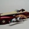
Peter Lombardo Posted November 30, 2009 Author Share Posted November 30, 2009 Ok, we finished up the Christmas lights, they came out very nice, but I could not wait to get in and fire up the vacuum machine and make a copy or two of the XP45C. I put the top and the bottom sections on the vacuum plate, heated up the plastic and ran off a copy. There are two imperfections on the car, the driver side front wheel face, that gets removed anyway, and a small glitch on the driver rear, but that is easy to correct. I had a difficult time getting the mold out of the body, but with a little cutting it popped out. So here is the body. It needs to have a few small imperfections fixed, all very easy and the lower body pans added, doors, truck lid and windows cut in, but all and all, this is going to be fun. The other day I made a quick vacuum body in clear, so I can cut the windows out of that body and use them in this one, as they have the proper curves in them. I think you guys are tired of this posting, so I will not return to it until I have the panels opened and ready for the chassis and interior work. Thanks for looking. Quote Link to comment Share on other sites More sharing options...
Custom Hearse Posted November 30, 2009 Share Posted November 30, 2009 I'm not tired of it! I'm seriously enjoying seeing the process! Please don't end it... Quote Link to comment Share on other sites More sharing options...
charlie8575 Posted November 30, 2009 Share Posted November 30, 2009 Very interesting, Peter. My complements to you. Charlie Larkin Quote Link to comment Share on other sites More sharing options...
Recommended Posts
Join the conversation
You can post now and register later. If you have an account, sign in now to post with your account.
Note: Your post will require moderator approval before it will be visible.