fractalign Posted August 11, 2014 Author Share Posted August 11, 2014 (edited) Later on I decided to add a rear flange to the cab, this was originally to go on the lower panel but I decided to put it on the cab to keep the build consistent. Edited August 11, 2014 by fractalign Quote Link to comment Share on other sites More sharing options...
fractalign Posted August 11, 2014 Author Share Posted August 11, 2014 Here is how the two fit up, the lower panel still needs tidying up and to do this I will reinforce the inside and smooth it out. Quote Link to comment Share on other sites More sharing options...
fractalign Posted August 11, 2014 Author Share Posted August 11, 2014 I sanded down the outside of the panel some more to get it to sit flush with the cab sides. I was going to run a belt line along the bottom of the panel but I decided not to because I don't think the original ones had them. One thing I will have to do is find a way to lock in the cab to the chassis to stop it slip[ping down and that will be the next task. Quote Link to comment Share on other sites More sharing options...
Chariots of Fire Posted August 11, 2014 Share Posted August 11, 2014 Just a suggestion for holding the cab in place. Glue a small tab to the inside edge of the frame rail web about 3mm square. With the cab in place glue another tab to the inside of the cab so that it sits directly over and touches the tab on the frame. Do not glue the two together. Holding the cab in place drill a hole up from the bottom through both tabs. Insert a piece of brass rod the same size as the holes you drilled into the tab that is glued to the cab. Glue that in place in the tab on the cab only. Do the same to the opposite side. The pieces of brass rods will then be directly in line with the holes in the tabs on the frame and will provide stability and alignment every time. Quote Link to comment Share on other sites More sharing options...
tbill Posted August 11, 2014 Share Posted August 11, 2014 this is coming along great! nice work so far. this is a cool project Quote Link to comment Share on other sites More sharing options...
fractalign Posted August 12, 2014 Author Share Posted August 12, 2014 Thanks for the positive feedback and advice guys. I did not get anytime to do anything today but I will be back on track with the build tomorrow. Quote Link to comment Share on other sites More sharing options...
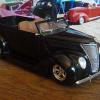
fractalign Posted August 14, 2014 Author Share Posted August 14, 2014 (edited) Hey Guys. I finally got back on track with the build today after a few days off, focussing on another build. This image shows what I am aiming for with this build. The main changes I have made include to the windscreen area, I am halfway through making it a flat unit like the 35 and 36,s and the wheel arches, they have been enlarged. Another very important change is to the lower cab section, this is now part of the fender units, this will make adding the cab a lot easier because instead of having the upper and lower section there will only be the upper section as the lower section is now integrated into the fenders. By doing this I have also made the fenders more rigid because without a floor they needed a replacement form of structure. Edited August 14, 2014 by fractalign Quote Link to comment Share on other sites More sharing options...
fractalign Posted August 14, 2014 Author Share Posted August 14, 2014 The windscreen was surprisingly easy. All I did was cut through the centre at the top and make a cut along the width of the frame with the angle grinder. Because the angle grinder cut was at least a millimetre wide, the frame was pushed back into this space, effectively flattening it. I will do the same for the lower part of the frame as well. The strip of balsa wood acted as a frame to hold the newly reshaped frame together. This has now been filled with putty. Quote Link to comment Share on other sites More sharing options...
fractalign Posted August 14, 2014 Author Share Posted August 14, 2014 One thing I will be doing now that I have worked out how to properly reshape the windscreen is to fix up the one on the white cab, which is very rough. Quote Link to comment Share on other sites More sharing options...
fractalign Posted August 14, 2014 Author Share Posted August 14, 2014 (edited) The white kit is the conventional one and checking it against the chassis shows that it will need to come down 1mm or so to sit flush. Because I need to retain the floor in this one, I came up with a solution. Edited August 14, 2014 by fractalign Quote Link to comment Share on other sites More sharing options...
fractalign Posted August 14, 2014 Author Share Posted August 14, 2014 (edited) The area marked in black texta pen will be sanded down forming channels for the chassis rails to slot into. That will lock the two together and make them flush as well. Next task will be to do this and to continue working on the other cab. Edited August 14, 2014 by fractalign Quote Link to comment Share on other sites More sharing options...
fractalign Posted August 16, 2014 Author Share Posted August 16, 2014 (edited) Hey Guys. I have taken some time out from the cab to focus on the chassis. Because the two are interconnected getting the chassis up to date will make the placement of the fenders a whole lot easier. I put several layers of undercoat on it this morning. And having done that I re-punched the holes in the front crossmember for the axle u bolts to go through because they had filled with paint. The u bolts them selves were made from the binders of old notepads. These old not pads are a good source of materials because the plastic covers themselves are perfect for making up door trims etc, due to their grainy surface. The wire once un wound can be bent into shape four just about any thing. I will using the same binding four my engine wiring for future projects. The other thing I did was cut back the surrounding at the rear of the front crossmember. On these larger truck chassis, the engine mounts and crossmember are combined. Edited August 16, 2014 by fractalign Quote Link to comment Share on other sites More sharing options...
fractalign Posted August 16, 2014 Author Share Posted August 16, 2014 (edited) Checking the fit go the engine. This block is from the the Lindberg 34 Pickup because this chassis was originally only going to be used for the 32 and 34 BB trucks that I am working on. When I googled some images of the 35/36 Ford trucks I realised there was very little difference between them and their earlier BB counterparts, so that was when I decided that it would be easier top adapt the 35 body to this chassis rather than create a new chassis. I was originally going to finish this chassis first then cast one, cut off the front and graft the front of the pickup chassis onto it. When I saw the google image I realised that the front half of the pickup and truck chassis were completely different. The truck chassis is straighter and deeper. The main difference between the 34 Lindberg engine block and the Monogram 36 engine block is in the engine mounts brackets found on the blocks so I will need to work out a way of adapting the two engine types to the one set of engine mounts. Edited August 16, 2014 by fractalign Quote Link to comment Share on other sites More sharing options...
fractalign Posted August 16, 2014 Author Share Posted August 16, 2014 Another thing I did was peg up the fenders and chassis with the front end to see how the wheel fits into the front fender bay. Its not to bad and i should ad that the front end sitting under it in these shots is actually the pickup front end. Quote Link to comment Share on other sites More sharing options...
fractalign Posted August 16, 2014 Author Share Posted August 16, 2014 To get the ride height, I will need to make up some inner fender panels. These will act as spacers as well as flanges to lock the fenders onto the front of the chassis. These inner fender panel will most likely be attached to the existing fenders rather than be separate units. Quote Link to comment Share on other sites More sharing options...
fractalign Posted August 16, 2014 Author Share Posted August 16, 2014 I am undecided as to which front end I want to run under this truck. While the one from the 37 pickup looks the part it is a little narrow. The other axle is for the BB trucks. I was thinking of casting this one and adapting the axle to the 37 leaf spring wishbone assembly until realised that the leaf spring on the 37 is actually wider than the BB leaf spring. What I might do is widen the 37 axel at either end to bring it into line with the BB axle. Quote Link to comment Share on other sites More sharing options...
fractalign Posted August 16, 2014 Author Share Posted August 16, 2014 (edited) In my previous post I was talking about the reducing the gap between the chassis and the floor on the other set of fenders by creating channels for the chassis to lock into the floor pan. The problem with doing this is that ride height is sacrificed at the same time the gap is eliminated. I have come up with a solution where by ride height is retained and the gap is eliminated. All will be revealed in the next post. Edited August 16, 2014 by fractalign Quote Link to comment Share on other sites More sharing options...
southpier Posted August 16, 2014 Share Posted August 16, 2014 this definitely a "labor of love"! Quote Link to comment Share on other sites More sharing options...
fractalign Posted August 19, 2014 Author Share Posted August 19, 2014 Hey Guys. A long over due update on the project, I have been preoccupied with another build but I took time out from it to work on the truck, namely the front end. In the last post I was unsure if I was going to use the kit axle because it was a little narrow. Well I solved the problem. First I cut each stub axle off. Taking some thick plastic tubing, sprue, I cut to lengths and glued them onto each end and then reattached the stub axels. The fit axel to did not have these pivot points, so in real live this axel would not steer. With the stub axels corrected, I drilled holes in each one. The steering brackets will attach to these. Quote Link to comment Share on other sites More sharing options...
fractalign Posted August 19, 2014 Author Share Posted August 19, 2014 The other thing I did was add some half round to the base of the wish bone, the other side is yet to be done. The axel now looks like a proper truck axel and not a pickup axel. Sorry there are no more photo's but I have been flat out packing today because I am going a way for a week or so. When I return I should have a fresh batch of model building material so that i can really get back into the build. Cheers. Quote Link to comment Share on other sites More sharing options...
Danno Posted August 19, 2014 Share Posted August 19, 2014 Keep in mind, Robert, the Revell '37 Ford pickup and panel kits replicate passenger car based light commercial vehicles. The larger truck you are modeling would use the same front axle as the BB, not the smaller axle from the passenger car/light commercial series vehicles. Quote Link to comment Share on other sites More sharing options...
slusher Posted August 19, 2014 Share Posted August 19, 2014 Nice progress. Looks really good.. Quote Link to comment Share on other sites More sharing options...
fractalign Posted August 19, 2014 Author Share Posted August 19, 2014 Keep in mind, Robert, the Revell '37 Ford pickup and panel kits replicate passenger car based light commercial vehicles. The larger truck you are modeling would use the same front axle as the BB, not the smaller axle from the passenger car/light commercial series vehicles. So what you are saying is that I should modify the BB axel that I am using for the 32 and 34 truck and use it instead, if thats the case, I will do that instead. Cheers. Quote Link to comment Share on other sites More sharing options...
greymack Posted August 26, 2014 Share Posted August 26, 2014 Awesome looking truck man and one of my favorite era's of trucks too Quote Link to comment Share on other sites More sharing options...
fractalign Posted August 26, 2014 Author Share Posted August 26, 2014 Hey George. The Thirties were indeed a golden age for truck design. It was the birth of the big rig with makes such as Faogel the forerunner to Peterbilt, Federal, Kenworth and Diamond T all building ever larger trucks. The first truly modern semi trailer based trucks all evolved from this era. Quote Link to comment Share on other sites More sharing options...
Recommended Posts
Join the conversation
You can post now and register later. If you have an account, sign in now to post with your account.
Note: Your post will require moderator approval before it will be visible.