fractalign Posted June 18, 2015 Author Share Posted June 18, 2015 With the transmission cross member in place. Quote Link to comment Share on other sites More sharing options...
fractalign Posted June 18, 2015 Author Share Posted June 18, 2015 Without a doubt the most frustrating part of this build was sourcing wheels. For two years I tried a number of different methods from scratch building them, to looking for aftermarket wheels to even buying a 1:24 scale diecast kit to get the wheels off. I even tried scanning and 3d printing a 1:1 wheel that I owned, before buying the diecast kit. Nothing worked, I had settled on using the diecast wheel until I broke it from over machining. That was a good thing because it was far from accurate to begin with, even with my improvements. With that wheel broken it was back to the drawing board and scratch building another wheel. This time I would plan everything out. not only did the stud and hole placement need to be even, the disc face need to be correct as well. Here is what I came up with. Although far from perfect its a vast improvement on anything else I have seen. I have not worked out how I will create the outer rim yet but I have a few ideas in mind. Quote Link to comment Share on other sites More sharing options...
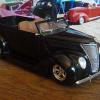
fractalign Posted June 18, 2015 Author Share Posted June 18, 2015 The wheel and drum sitting around the stub axle. The next task will be to get the rest of the chassis finished then I can move onto completing the wheel and front end. Quote Link to comment Share on other sites More sharing options...
olsbooks Posted June 18, 2015 Share Posted June 18, 2015 WOW! Just a 2 cent suggestion on the outer ring. A trip to the hardware store and look in the plumbing section for hard plastic washers. Those used on the joints of plastic drain pipes on bathroom sinks come to mind. I seem to recall seeing some in good mom and pop hardware stores of all sorts of diameters. The other thought is I have had good luck with a bit of patience and more patience is bending small Evergreen "L" channel over a piece of pipe after sticking it in hot water and using a hairdryer. Good luck. Most impressive work! Peace. Quote Link to comment Share on other sites More sharing options...
gatorincebu Posted June 18, 2015 Share Posted June 18, 2015 Bloody el ! this has to be one of the most comprehensive build threads I have seen here. Your work on this project is inspiring. This will be a really cool and unusual model when completed. Be Well Gator Quote Link to comment Share on other sites More sharing options...
fractalign Posted June 19, 2015 Author Share Posted June 19, 2015 Thanks for the positive encouragement guys ! Quote Link to comment Share on other sites More sharing options...
3100 chevy Posted June 19, 2015 Share Posted June 19, 2015 I just noticed this, Wow! Quote Link to comment Share on other sites More sharing options...
Superpeterbilt Posted June 19, 2015 Share Posted June 19, 2015 Excellent work. Good to see you back on it. Quote Link to comment Share on other sites More sharing options...
Tesla Posted June 19, 2015 Share Posted June 19, 2015 I applaud you for your determination to build an accurate model. What you've done so far is exceptional! Quote Link to comment Share on other sites More sharing options...
fractalign Posted June 21, 2015 Author Share Posted June 21, 2015 Thanks for the encouragement guys, I managed to get the fourth cross member added and undercoated today. There is only the rear cross member left now. Once they are all in place I can add the remaining studs and the chassis will be finished. I hope to have some photos up tomorrow. Cheers ! Quote Link to comment Share on other sites More sharing options...
fractalign Posted July 10, 2015 Author Share Posted July 10, 2015 (edited) Hey Guys. Hey Guys. I thought it was time for a quick update on the build, it has been painstakingly slow. At the moment I am working on getting the wall thickness of the rails to be uniform. The idea will be to be able to swap the cross members over from their respective positions and have them be interchangeable between each other. This will only apply to the last three cross members where the rails are straight and square. The front half of the chassis bows out to so its not possible to do the same here, also the wall depth decreases as it gets closer to the frame horns. Even so I will be working to get the wall thickness uniform here as well so that the respective cross members can reversed and slot back in equally. Its vital that I get this correct before I finally add the cross members. One thing that I changed was the width of the chassis, its now at least a couple of millimetres more narrow which will make it easier to fit the rear end in. It will take time to get the balance right but the upside is that the chassis will be far better than originally planned. The biggest change though has been in the second last cross member that lines up with the front of the leaf springs. This is the most complex of all the cross members. Along the bottom, the edge is arched and flanged, along the top there is a recess at either end where the triangular brackets join it to the top of the chassis rails. While these features were obvious in the sourced images there was something that was not as noticeable. Looking down from above the walls actually bow out. I needed to make this change and so I sliced along the length of the cross member and added material to the centre. The diagram below shows the cross member and its shape. Next task will be to get the wall thickness finished and then add the cross members. Edited July 10, 2015 by fractalign Quote Link to comment Share on other sites More sharing options...
Chariots of Fire Posted July 10, 2015 Share Posted July 10, 2015 (edited) I'm going to draw up a suggestion for you based on the rim you show. I think it would work for you. Here it is. Edited July 10, 2015 by Chariots of Fire Quote Link to comment Share on other sites More sharing options...
fractalign Posted July 11, 2015 Author Share Posted July 11, 2015 Thanks for that information ! I will certainly be following up with it once the chassis is finished ! Quote Link to comment Share on other sites More sharing options...
fractalign Posted July 21, 2015 Author Share Posted July 21, 2015 (edited) Hey Guys. It has been a while since I put anything up of the build, not because I have I have stopped working on it more for the fact that has taken so long to get any thing done. I have worked solidly to get the chassis finished. This has been tedious to say the least. Getting the inside of the rails to the same wall thickness and getting the cross members right has taken me weeks to work out. I finally put the chassis together last night and layed primer on it today. In order to make sure all the cross members were sitting evenly I blew this image up to 285 percent which is the same size as the actual chassis. This is a kind of digital jig so to speak. The second last cross member is actually sitting over the one in the image. With the chassis only needing the studs to finish I have turned my attention to the differential. You can see the actual diff is much longer than the one in the diagram. Also the enclosed driveshaft on the one in the image tapers in towards the transmission. Edited July 21, 2015 by fractalign Quote Link to comment Share on other sites More sharing options...
fractalign Posted July 21, 2015 Author Share Posted July 21, 2015 To make the tapered drive shaft I used synthetic baking clay known as Fimo. I stretched and rolled a piece to the same shape as the one in the image. After taking it out of the oven I sanded out the the imperfections by hand. No lathe means this is slow work. But I have glued the length to the diff centre and its a lot shorter than how it looked before the modification. The wishbones are from the Revell 37 Pickup kit. When I baked up the drive shafts I also baked up a length for the shafts that sit either side of the diff centre. The will be added later. I also managed to finish constructing the outer rim of the wheel. I used five lengths of 1mm by . 0.3 mm strip. To avoid damage to the centre disc. I used strips of double sided tape to fasten the first band to the wheel. There are three bands in total. The inner and outer bands consist of two strips one on top of the other. The centre band is just a single strip. On the 1:1 wheel there is a concave channel between the two bands this single strip represents that. The next task will be to finish off the diff and clean up the holes in the wheel. Quote Link to comment Share on other sites More sharing options...
fractalign Posted July 21, 2015 Author Share Posted July 21, 2015 (edited) The bottom three holes are ok but the top two need some work. It will take a while to get it right but this is the closest I have ever come to scratch building a wheel that I am truly happy with. I have done several previous to this one but none have come close to this one for the correct shape. I actually own an original 1:1 pair of these wheels so I will reference this one against the original until I am happy with it. Edited July 21, 2015 by fractalign Quote Link to comment Share on other sites More sharing options...
Tesla Posted July 21, 2015 Share Posted July 21, 2015 Very good progress and the FIMO clay sounds interesting! It's the first time I've heard of this product. Quote Link to comment Share on other sites More sharing options...
fractalign Posted July 22, 2015 Author Share Posted July 22, 2015 Its well worth using, once baked it takes on the same properties as resin or styrene plastic, it can be sanded and glued to regular parts. Quote Link to comment Share on other sites More sharing options...
fractalign Posted July 22, 2015 Author Share Posted July 22, 2015 Hey Guys. Tonight I focussed on the differential. That included making up the shafts that attached to the centre. Here is where things stand. Right side up ! I also decided to see who things would look with the cab sitting on top of the chassis. It looks odd at the moment due to the fact that I have not made up the tandem rear end. Of course I will need to mould this differential to do that along with the rest of the wheels once I have finished the wheel. Before I do that I will need to add the cross member studs to the chassis. The front ones were added a while back so the front is effectively complete. That will be the next task and once I Have done that the chassis will be finished at last ! Quote Link to comment Share on other sites More sharing options...
gatorincebu Posted July 24, 2015 Share Posted July 24, 2015 Robert, I am really enjoying following this build thread. Your attention to detail is astounding. Cheers. Be Well Gator Quote Link to comment Share on other sites More sharing options...
fractalign Posted July 28, 2015 Author Share Posted July 28, 2015 Hey Guys. Sorry for the lack of updates, work has slowed a bit, I am putting the finishing touches to one of the cross members on the chassis. With the chassis itself almost done I have also turned my attention back to the cab. One area in particular that I would like to finish is the hood. Anybody who has been following since last year would know that I have scratch built this particular hood. The swage on the one in the image takes on a beak like appearance which I recreated on my own version. I am in the process of making sure both swages are asymmetrical. The second image is a diagram that shows just how different the Dearborn C.O.E is from the conventional Ford truck that its based off. I did not have this diagram when I started working on my own version so there was some guess work involved on my part. I will of course cross check my version with the diagram to insure accuracy because the next task once the hood and cab are finished will be to mould them. Quote Link to comment Share on other sites More sharing options...
Chariots of Fire Posted July 29, 2015 Share Posted July 29, 2015 That's a lot of work but very effective. I really like your approach to this. All in good time as they say. Quote Link to comment Share on other sites More sharing options...
fractalign Posted August 5, 2015 Author Share Posted August 5, 2015 Hey Guys ! I have been a bit slow with the project of late. In my last post I said I would turn my focus back on the cab and the hood in particular, well I reshaped the beak shaped front swage and it looks more asymmetrical. With that worked out I was concerned with the filler panel between the chassis and the cab. The original one was attached to the fenders and I had begun the process of reinforcing the inside walls with car bog to make the whole easier to mould. I realised this would be a mistake so I decided to build a new one rather than finish the old one. I purchased some more styrene over the weekend and used some for this new panel. In order to make sure the top of the panel followed the bottom swage at the rear of the cab, a piece of Fimo was pressed into the cavity to create an impression. Fimo is a form of synthetic baking clay perfect for this purpose. Once baked, the piece was trimmed, sanded and attached to the top of the panel. Over the next few day I am going to concentrate on making sure this panel looks exactly like the ones in the archival images. I have also decided the panel will be a separate from the fenders to make both units easier to mould. Quote Link to comment Share on other sites More sharing options...
fractalign Posted August 19, 2015 Author Share Posted August 19, 2015 (edited) Hey Guys. Still working away, just realised its been over a year now, actually a year and three weeks, where has the time gone ? Anyway there have been a few changes, some major ones at that. One of the changes is the trucks themselves. I was originally going to have two 35/36 Dearborns and a 35/36 Regular Ford. I have decided to replace one of the 35/36 Dearborns with a 37 Dearborn.I have three grills and a cab left over from this project and I decided I should put it to use. Visually there is not a lot of difference between the 36 and the 37 Dearborn. The hood on the 37 encloses the grill and the grill itself is much taller than the standard grill other then that everything else will be the same. Not sure which one I prefer, the 36 or 37 but either one looks better then Ford's first Factory C.O.E the following year. Edited August 19, 2015 by fractalign Quote Link to comment Share on other sites More sharing options...
Chariots of Fire Posted August 19, 2015 Share Posted August 19, 2015 The '37 looks more like it should be whereas the '36 looks like the grill is so out of place. A first stab at designing and using what you have I guess. Still the oversized cab and small fenders on both rigs do look a bit odd. Like your work on this one. And there has been a lot of it! Don't fret the time it has taken. Took me 2-1/2 years to complete my '37 Seagrave. Quote Link to comment Share on other sites More sharing options...
Recommended Posts
Join the conversation
You can post now and register later. If you have an account, sign in now to post with your account.
Note: Your post will require moderator approval before it will be visible.