dptydawg Posted January 20, 2008 Share Posted January 20, 2008 This is a little background on my current modeling project. For the past several months I have been slowly piecing together a 1/25th scale model of a Sandy Construction Gravel crusher. From the mid 30's to the mid 50's Tom Sandy built these gravel crushers in Goderich Ontario. The unique design was patented by Mr. Sandy. These units were very popular with the local contractors in Western Ontario. Several of these old crushers still survive and a few are still in operation. Since my uncle and later his son owned a Sandy crusher as well as several other of my friends had Sandy crushers cross their paths, I decides that I had to build one to preserve some of the local history of the area. What follows is a chronicle of my build with some pictures of the real thing plus my model. For those forms that have a 3 picture rule per post, I'll try to stay close to your limit and post often. The most distinctive feature if these machines in the revolving cylindrical screen Gravel that passed through the screen was pushed out by the paddles on the screen to a conveyor belt to a waiting truck. If the rocks were too large to pass through they were scooped up to the top of the screen then dropped into the jaw crusher which cracked the rocks into smaller pieces. These were either sent to the conveyor belt or again carried to the top and this time dropped into a roll crusher. The cycle repeated until the rocks were small enough to pass through the screen. The machine was powered by a diesel engine. Usually a UD14 International or a 3-71 Detroit Diesel via a flat belt drive. Some have been converted to run off tractors pulleys Thnks for looking Carl Avis Quote Link to comment Share on other sites More sharing options...
dptydawg Posted January 20, 2008 Author Share Posted January 20, 2008 the first part ...building the Screen I Started this project by building a screen. The overall diameter is about 120 inches. The length is 6 ft. Since I scratch build at 1mm = 1 In. The screen is 120mm dia. X 72mm long. When I started I didn't have large enough sheets of Evergreen to cut the rings so I built the rings from segments The 3 rings were tied together with 2X2 stringers to form a cylinder. After the glue had cured I wrapped nylon window screen over the outside of the cylinder to form the screen. I then installed strips of styrene over the outer edges of the screen. This is the wear ring where the drove wheels for the screen run. Next I installed the scoops and buckets inside the screen to pick up the large stones for further processing. I also installed strips across the outside of the screen. These are the paddles that push the gravel out of the crusher and onto the conveyor belt. Looking at the rear of screen And the front of the screen These crushers are constantly exposed to the elements as well as the abrasive conditions of rock dust therefor there is little or no paint left on them but they are well rusted. The primary colour is rust in about 10 different shades to be continued Thanks for looking Carl Avis Quote Link to comment Share on other sites More sharing options...
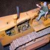
dptydawg Posted January 20, 2008 Author Share Posted January 20, 2008 The Jaw Crusher The unique design of the crusher jaws were patented by Tom Sandy in 1935. I used his patent office drawings to help build my model From these drawings and field measurements of old crushers, I made a pasteboard/masking tape mockup of the jaw frame. This I used to check for clearances on the model From the mockup I then cut the various bits from Evergreen sheet and strip styrene Which were then built up into the various components of the jaw crusher. The shafts were turned from 6mm plastic knitting needles. The eccentrics and cam rollers were turned from 10 mm knitting needles. The jaw plates were made by gluing 2mm half round strips to a 1mm plate. The pillow bearings are trailer landing wheels that were cut in half then glued to a plastic block and the whole assembly was drilled to clear 6mm a #B drill bit. The Roll Crusher Along the left side of the jaw crusher there is a roll crusher which does the secondary and final crushing of rocks. I built the support frame from surplus truck and trailer frame parts in my parts box. The rolls are built up from a pair of truck brake drums. The hubs were cut from the drums and used on the frame as bearing caps. The structure on top of the jaw frame is the feed hopper which directs rocks dropping off the screen buckets into the jaws. With all the pieces fabricated the jaw was ready for painting and assembly. The pillow blocks are held in place with small screws that were pillaged from an obsolete camera. This allowed for assembly for fitting then dismantling for painting and reassembly again. Quote Link to comment Share on other sites More sharing options...
dptydawg Posted January 20, 2008 Author Share Posted January 20, 2008 (edited) Paint and Assembly Once painted with some battle ship gray and a lot of shades of rust the jaw was reassembled This is a shot of the bottom showing the tension rods which hold everything tight against the toggle plates. The springs allow movement as the cam rollers follow the eccentrics on the main shaft. This is a front view with the various parts labled. Still to add are gearboxes and chain case covers on the right end of the main shaft and a pair of flat belt pulleys on the left end. Main drive pulley All power used by the crusher is transmitted from its diesel engine via a flat belt to the main cam shaft, which acts like a layshaft and distibutes power through pulleys, gears and chains to the rest of the machine. The main pulley is 48"X 9"flat pulley. The rim is a 9mm slice from a plastic container. The spokes are 1.5 X 4 mm Evergreen strip with 2mm half round added to both sides. The hubs are 5mm slices of 10mm kniting needles. The centre was drilled to fit the main shaft. Ther is a secondary 15" pulley outboard of the main pulley. A 15" mag rim from the parts box was dechromed and machined flat to form this pulley Both pulleys were painted Neutral Gray then weathered with several rust colours. The pully faces were painted metaloc gary them brushed with dark metalizers, and steel. The faces were coated with future to give a shine like worn metal from belt friction. this is where I'm at curretly with my build. The next phase is to mount the various components onto the frame of the crusher. As I make progress I'll post more pictures Thanks for looking Carl Edited January 21, 2008 by dptydawg Quote Link to comment Share on other sites More sharing options...
Jefbo Posted January 21, 2008 Share Posted January 21, 2008 Hi Carl, That's amazing work! Thanks for posting all the photos. I will keep coming back to see how this one comes together. Jefbo Quote Link to comment Share on other sites More sharing options...
mackinac359 Posted January 21, 2008 Share Posted January 21, 2008 WOW! Most impressive. Tim Quote Link to comment Share on other sites More sharing options...
lonewolf Posted January 21, 2008 Share Posted January 21, 2008 Carl, Great job on a build that I've never seen attempted before. Having worked in construction for 30 years, I've got to say you're really nailing this one. I'll be following this one and look forward to seeing the finished product. Quote Link to comment Share on other sites More sharing options...
Old Albion Posted January 21, 2008 Share Posted January 21, 2008 Carl, This is without doubt an Outstanding Piece of Model Engineering. Very Impressive! This would be an excellent load for an Old Low boy trailer pulled by an Old weathered Pete 351 or maybe a White Diesel Truck. Quote Link to comment Share on other sites More sharing options...
dptydawg Posted January 22, 2008 Author Share Posted January 22, 2008 HI Guys Thank you all for the kind words. These Sandy Crushers were sort of legend in the local construction folklore. I really enjoy making construction models and scratch building. Since there is not a lot of consturctuion models offerd in 1/25th scale, I started to build th eodd one on my own. The crusher seemed like a natural. It has lots of interesting sub assemblies and since the original was essentially home made it did not have many compoud curves to form. It has however taken much longer than I figured it would. It seems that of the hundreds of referece pictures and measurements I took I always managed to miss something critical for building it. These crushers were built as a trailer to be mobile. The rear axles were old truck rearends with the pots removed. They didn't bother with springs or brakes either. I suspect that they were pulled by single axle gas powered tractors. thanks for looking Carl Quote Link to comment Share on other sites More sharing options...
dptydawg Posted February 5, 2008 Author Share Posted February 5, 2008 I spent a good chunk of the weekend trying to get some more done to the crusher. These are some pictures of the various modules mocked together. I hope it gives some sense of the finished machine. Once I install the front screen supports the screen is locked in, therefore I have to paint and weather everything before final assembly I discovered a SpecCast diecast 1937 Ford pickup with an Resin International U2 gas engine in the bed. While its not as big as the UD14 diesel engine on the prototype, I have it and don't have to scratch build one. I turned a new pulley for the engine and wrapped it with thread. Rope wrapped pulleys was one of the tricks used to increase friction between the pulley and the belt The rollers supporting the screen are inner wheel centres stolen from an AMT Lil Red Express kit. The red pulley is made from some old truck rims. it drives a differential that turns the screen. This shows the .differential Like the prototype it is a truck rearend that has been cut up and had mounting brackets welded on. The shiny thing in the background is may first attempt at the belly pan that goes under the screen. My sizing is off but the technique worked. I'll be making a better fitting one soon. I used some old aluminum press plate that I had. Its very soft and easy to work with. I built the stuff under the frame and infront of the screen as a module that I could paint and weather then hopefully install with minimum damage done to the rest of the model. The belly pan goes between the rollers, the paddles on the screen sweep any gravel that falls through the screen out onto the yet to be built conveyor belt. The black strip at the rear is the feed conveyor. I have it weathered and will remove it before the rest of the frame is painted Thanks for looking Carl Quote Link to comment Share on other sites More sharing options...
wiremonkey Posted February 5, 2008 Share Posted February 5, 2008 Awesome job on a unique build. Great to see somthing built entirely from scratch. Keep up the great work. Quote Link to comment Share on other sites More sharing options...
mackinac359 Posted February 5, 2008 Share Posted February 5, 2008 WOW! Tim Quote Link to comment Share on other sites More sharing options...
James W Posted February 5, 2008 Share Posted February 5, 2008 This is a great project. Thanks for the WIP pictures. I love the flywheel. Quote Link to comment Share on other sites More sharing options...
studioman3 Posted February 7, 2008 Share Posted February 7, 2008 Carl, Very impressive, the detail is awsome, it looks like you could throw some rocks in there and make ballast out of em. It is so neat to see someone make something out of nothing using only a few pictures and a great mind. You are very talented for sure and it shows. My dad does the same thing with wood and locomotives, just boggles my mind Nice job Tim PS. think you could do a 1-1 money minting press.................oops never mind Quote Link to comment Share on other sites More sharing options...
dptydawg Posted February 18, 2008 Author Share Posted February 18, 2008 I've made some more progress on the beast lately. Some of the painting and weathering as been done. I did a mock up of the frame without the screen to show the various components. the shafts still have to be trimed to fit. The froon end needs to be dirtied up a bunch. Here are ssome shots with the screen in place Thanks for looking Carl Avis Quote Link to comment Share on other sites More sharing options...
locoengr Posted February 21, 2008 Share Posted February 21, 2008 Thanks for looking Carl Avis NO! Thanx for posting!!!!! Outstanding work Carl. WOW is all I can keep saying when I look at your work! Quote Link to comment Share on other sites More sharing options...
dptydawg Posted March 22, 2008 Author Share Posted March 22, 2008 Hi All I finally got my crusher finished. I had a show deadline that kind of forced me into it. Here are a few shots of the finished product. and here's what the show ready piece looked like It will now become part of a gravel pit diorama Thanks for looking Carl Quote Link to comment Share on other sites More sharing options...
Clay Posted March 22, 2008 Share Posted March 22, 2008 I have been following this build since day 1, and I have been amazed the whole time. Love your work. Awesome job. Quote Link to comment Share on other sites More sharing options...
studioman3 Posted March 22, 2008 Share Posted March 22, 2008 WOW, a few thousand words come to mind here, but for time's sake I'll just leave you with a few. Friggin phenomenal! Darn nice work! Simply amazing! Tim Quote Link to comment Share on other sites More sharing options...
fkuaso Posted June 8, 2008 Share Posted June 8, 2008 ive said it before. im envious. Quote Link to comment Share on other sites More sharing options...
george 53 Posted June 8, 2008 Share Posted June 8, 2008 JUst saw this post and allI can say Is WOW!!!!!! You are definatly a VERY talented builder! Not a whole lot to say But I'll say it again,WOW!!!!!! Quote Link to comment Share on other sites More sharing options...
broch Posted June 8, 2008 Share Posted June 8, 2008 WOW!!! Just fantastic! It's really a special pice of work! Quote Link to comment Share on other sites More sharing options...
Recommended Posts
Join the conversation
You can post now and register later. If you have an account, sign in now to post with your account.
Note: Your post will require moderator approval before it will be visible.