
CrazyCrank
-
Posts
261 -
Joined
-
Last visited
Content Type
Profiles
Forums
Events
Gallery
Posts posted by CrazyCrank
-
-
Hello everybody
")
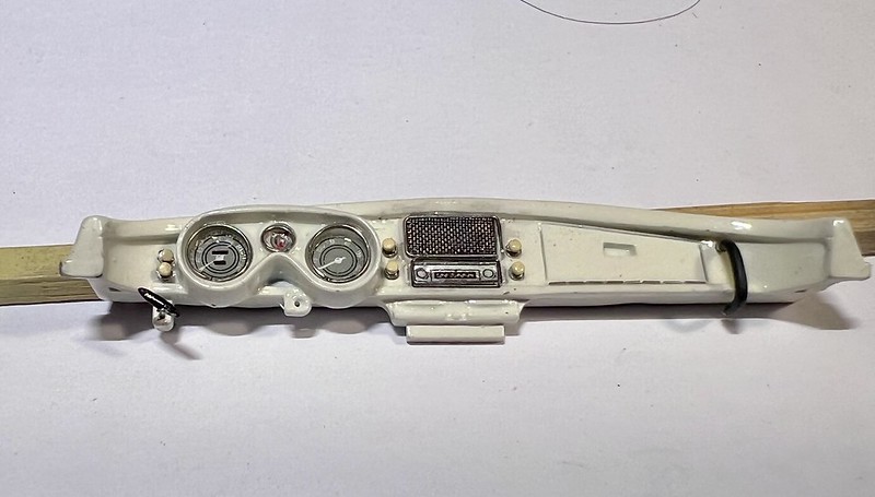
Today, I'll show you how I made and assembled all the dashboard components - part 1
- The dash was semi-gloss clear coated
- The decals have been placed, not without difficulty because those ones were very fragil. Used a lot of Microscale Microsol to soften them, but damaged a little bit the central one (not visible at the naked eye)
- Once dried, I sprayed a finale layer of 1K Gravity clear over the decals .... et voilà !

Next I 3-D drawn and printed a new handle for the handbrake (the lever I thought it was a starter, placed under the dash on the left side)
It will be painted with Molotov Chrome
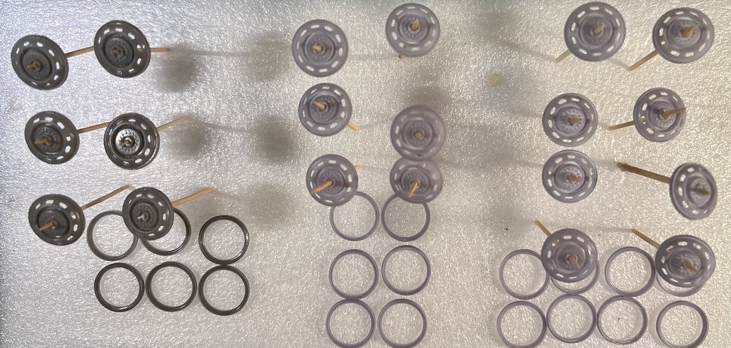
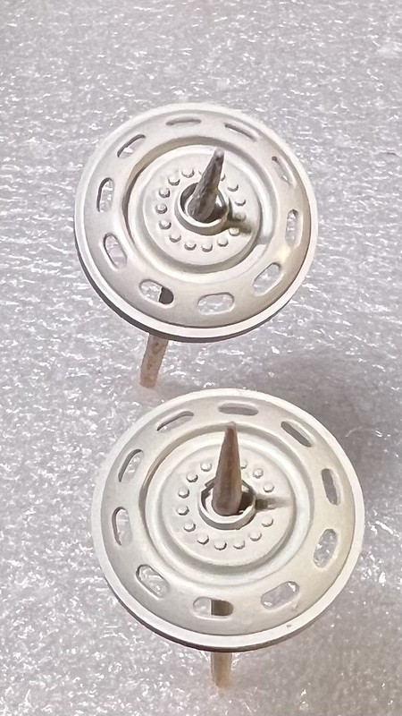
I 3-D drawn and printed the different knobs of the dash and radio
They will be painted ivory.
I 3-D drawn and printed a new passenger handle (placed on the right side of the dash, on the right of the glove box).
It will be painted matt black
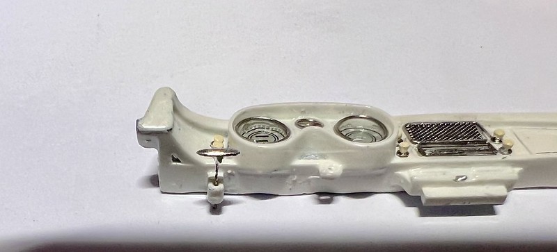
The meter's glasses have been improved using drops of Gauzy agent put on the decals. Once dried, it's fully transparent and shiny
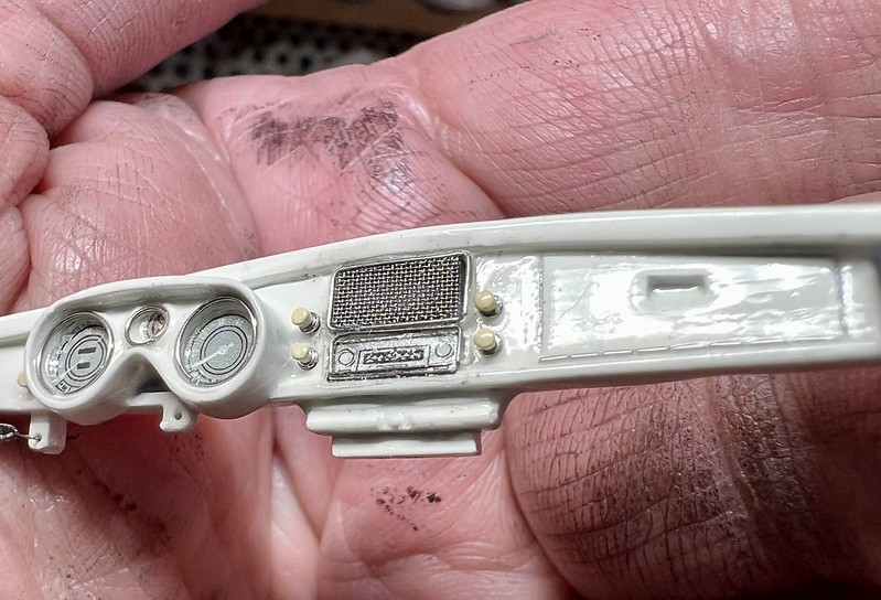
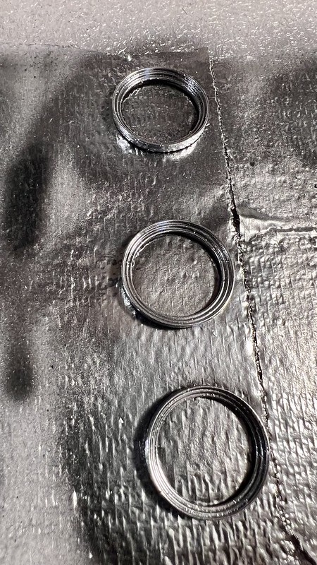
I've scratched the gauge's bezels, the elements of the fake glove box hinge, and the chrome frame of the speaker and radio with Nickel-Chrome 0.25 mm wire
I've already glued the bezels of the 3 meters and fabricated the fake hinge for the glove box.
All those little bits of Nickel-Chrome 0.25 mm rod have been glued using Gauzy agent (from AK), instead of Micro Liquid Tape, because it's much less thick, dries faster and if much more transparent.
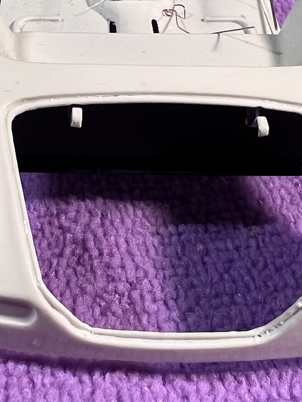
The thin mesh of the radio speaker, at the top center of the dash, was simulated inserting in the hole a rectangular piece of thin mesh (0.1 mm
It has not the right number of rows (30 would be needed to be accurate) but looks good imho.
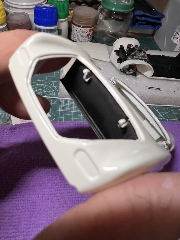
The grill is in place, and the meters's bezels as well:
Then, I painted chrome all the dash knobs that I'd resin printed.
And next, I brush painted ivory the buttons, under magnifying glasses
I had also painted chrome he passenger handle, because on its top end, there is as well a chrome bezel, and I've painted the handle Nato Black (AK 11360), which looks like a black leather.
The result is really nice :
The dash knobs an radio buttons were placed on the dash.
To highlight them, they have been painted light ivory instead of Pearl white, as the body.
We can see, on the closest photo, their chromed bezels
The handbrake handle was painted chrome and put in place:
Stay tuned if you like, and thanks for watching and criticising. ?
-
I do love your highly detailed engine bay ?
-
Hi guys
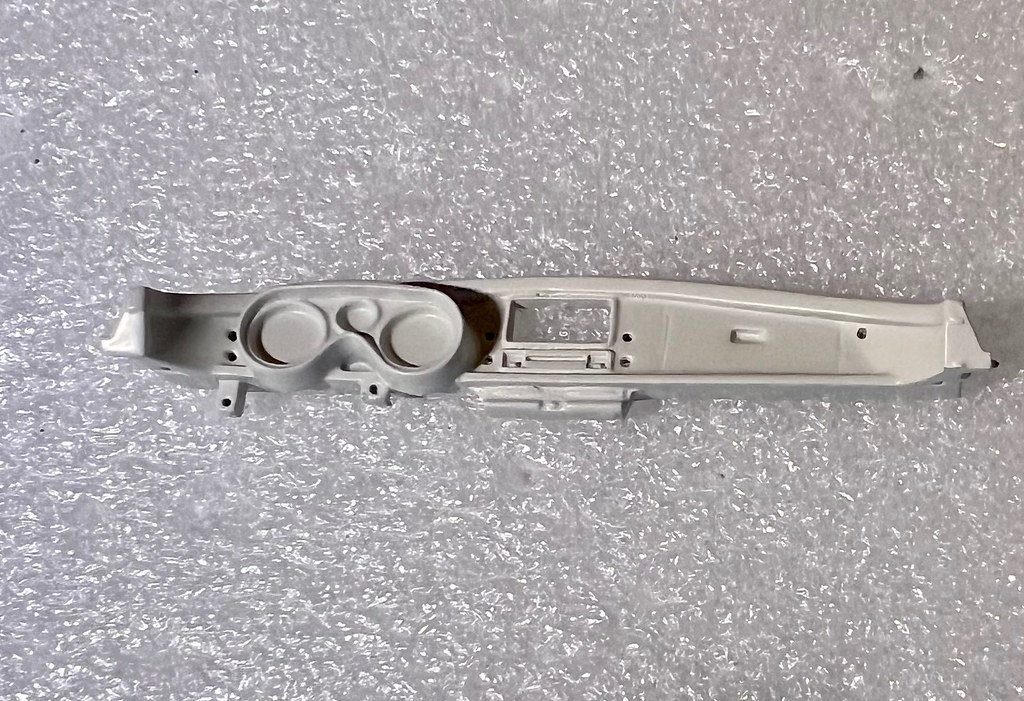
The dashboard I showed you painted with the new wheels isn't the kit part.
In fact the kit represent a BMW 507 Series I when Elvis's one was a Series II, which has a different dashboard, amongst many other features.
So, I hadn't any other option than make a new one...and what's more appropriate to do this job than 3D design and printing ?
Hereunder the kit dashboard, and a picture of a series II dash:
My drawing in Autodesk Fusion 360
All that stuff has been sliced, 3 pieces in 103% and 3 in 104% ( @Spiny ? )
And the 3D printed final part:
I presented it on the windscreen, because it's no impossible to follow the assembly instructions which ask to fix the dash on the cabin.
The new part will be attached to the windscreen frame:
-
In fact, as it is in the first post of this thread, she's not finished ?
Indeed, I've added the little detail that makes THE difference:
You should know that when The King finished his military service in Germany, he brought his car back with him to America.
He was already famous and his female admirers regularly left lipstick marks on the pearl-white bodywork of his BMW as they kissed it fanatically.
So much so that, fed up, he had it repainted red! !A model-maker friend of mine was able to produce 1:24 scale decals on his dedicated printer, based on a ‘lipstick kiss’ design I provided him with, and, because I thought it"s funny, I've affixed several of these decals to the bodywork and windscreen here and there, as a nod to the history of The King and this incredible car.
Let' see below some pics:
Enjoy
-
32 minutes ago, drodg said:
Beautiful masterpiece, congratulations.
Thank you for your kind words ?
-
23 hours ago, BK9300 said:
Truly masterful work - a pleasure to see it come all that way, from a basic kit, to its final, grand completion - amazing work!
Thank you for this great praise ?
17 hours ago, Rattlecan Dan said:Great attention to detail. Really nice build.
Thank you. I'm glad you enjoy it
4 hours ago, DoctorLarry said:Very nice and clean. I love the engineering that went into opening doors, trunk and hood. At first glance you would think it was the real car. Excellent!
Thank you very much ? The fuel filler flap over is also opening, and, much more, the sun visors are hinged and freely moveable
-
Morning guys
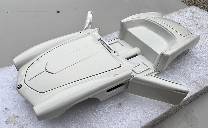
Clear coating of the body parts:
Some pics under artificial light
And under natural light during a cloudy weather
Trunk lid and trunk modifications:
Trunk lid:
I was inspired by this photo:
I've scratched, using 0.4 mm thick plastic plate, the panel which covers the inner side of the trunk lid, and drilled on it some 0.3 mm holes to simulate its screws fastening.
Later on, I'll thread into the holes some small sections of 0.3 mm steel rod, to simulate the screws.
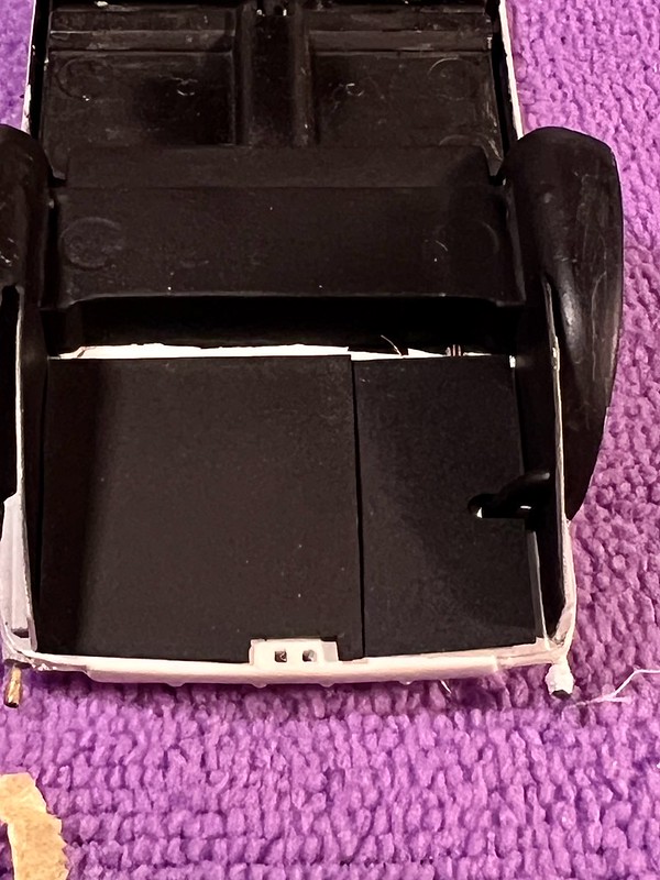
Trunk panels:
I've painted semi-gloss black the interior panels of the trunk, using a new method (for me at least) in order to get a grainy aspect which simulate, at this scale, a felt lining.
To do that, I used Tamiya Lacquer Semi Gloss Black LP 8, without thinning it, sprayed at 20 psi, with a very low paint flow, in several layers.
The rendering, at this scale, is far better than what I would have obtained If I had used flocking powder or thin adhesive velvet.
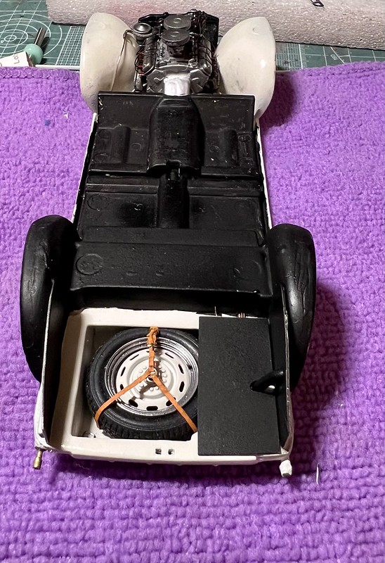
Invisible parts :
I've finished to scratch the fuel primary pump, adding two copper lines on my 3D printed part, after having painted it silver.
The part has been glued in place.
The same way, I've finished to scratch the fuel gauge, painted it silver and adding the electrical cables
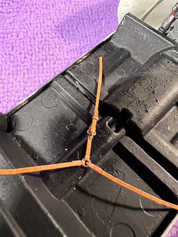
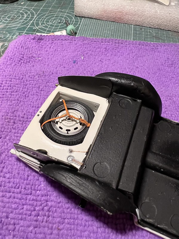
Spare wheel:
At least, I've installed the spare wheel straps in the trunk and placed the wheel in its housing.
That's all for now, guys
")
-
1 hour ago, NOBLNG said:
Believe me, it is well deserved! I also thank you for posting the techniques you’ve used. Outstanding results!??
Thanks a lot NOBNLG ?
If you are interested in scale modelling videos, you can subscribe to My YouTube channel
Most of my videos have English subtitles.
21 minutes ago, Justin Porter said:Really some seriously good improvements to what is not a bad kit, but one that does show its age in places.
Thank you very much ?
It's not a bad kit, but it's a very difficult one, due to the terrible fittings, the amount of flash, the poor quality of the plastic, which is either too hard, or too brittle, or too soft, and does not accept the paint easily!
-
3 hours ago, Misha said:
Amazing progress! The thought and focus combined with imagination and artistry with the technical building skills is exceptional!
Thank you for your detailed descriptions and photos; there is so much useful information for all of us.
Congratulations & cheers, Misha
Wow, what a lot of praise! Thank you very much, but I'm not sure I deserve it. ?
-
Hi guys
My apologies for not posting for a long time.
This build is finished and already posted in the "Under Glass" section.
However, I'm going to complete the WIP section of this charismatic car and share my tips and tricks with you.
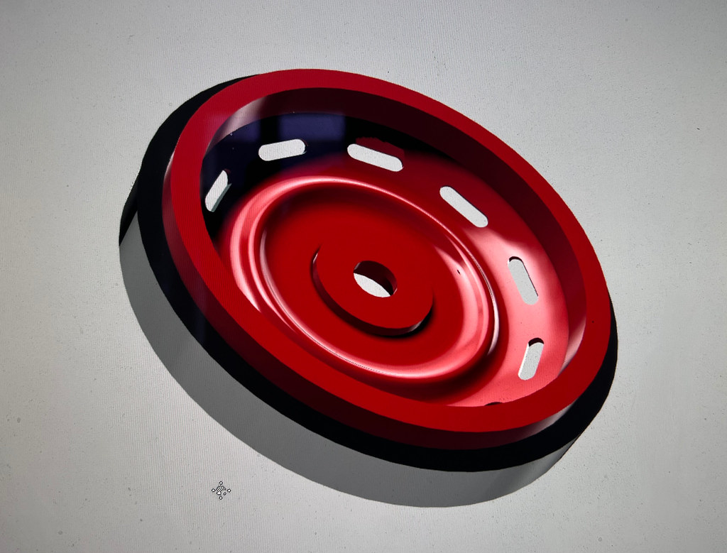
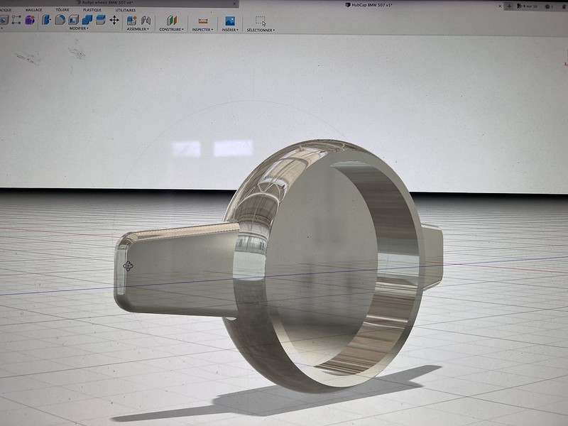
Wheels:
This BMW 507 was equipped with Rudge wheels, which are not supplied in the kit.
I spent some hours on Fusion 360 to draw the Rudge wheels, and the hubcaps.
In fact, I drew only the outer part of the rim, the inner part of the kit beeing correct.
Below the photos of the drawings
As you can see on the drawings, I've separated the rim in two sections, the peripheral, which is chromed, and the central section, which I've colored red for a better rendering (but will be Pearl white on the model, as on the real car)
And It's obviously possible to 3D print the two sections separately, and to reassemble them later.
This tip will allow to paint easily the 2 sections of each rim.
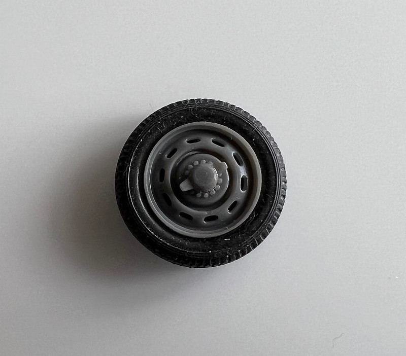
And here's the result after the second print attempt, and a tyre mounted on the rim.
The fitting with inner part of the rim and the wheel locker was excellent, so I printed separately 10 peripheral and 10 central parts of the outer rim
My workbench turned into a wheel factory :
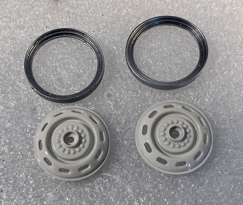
I painted the two parts of the outer half-wheel:
- Primer and 3 coats of Pearl White for the central part
- Primer, 2 layers of Alclad gloss black base, and 3 thin coats of Alclad Chrome for the peripheral parts.I also painted Alclad Chrome, the same way, my dozen of knock-off nuts.
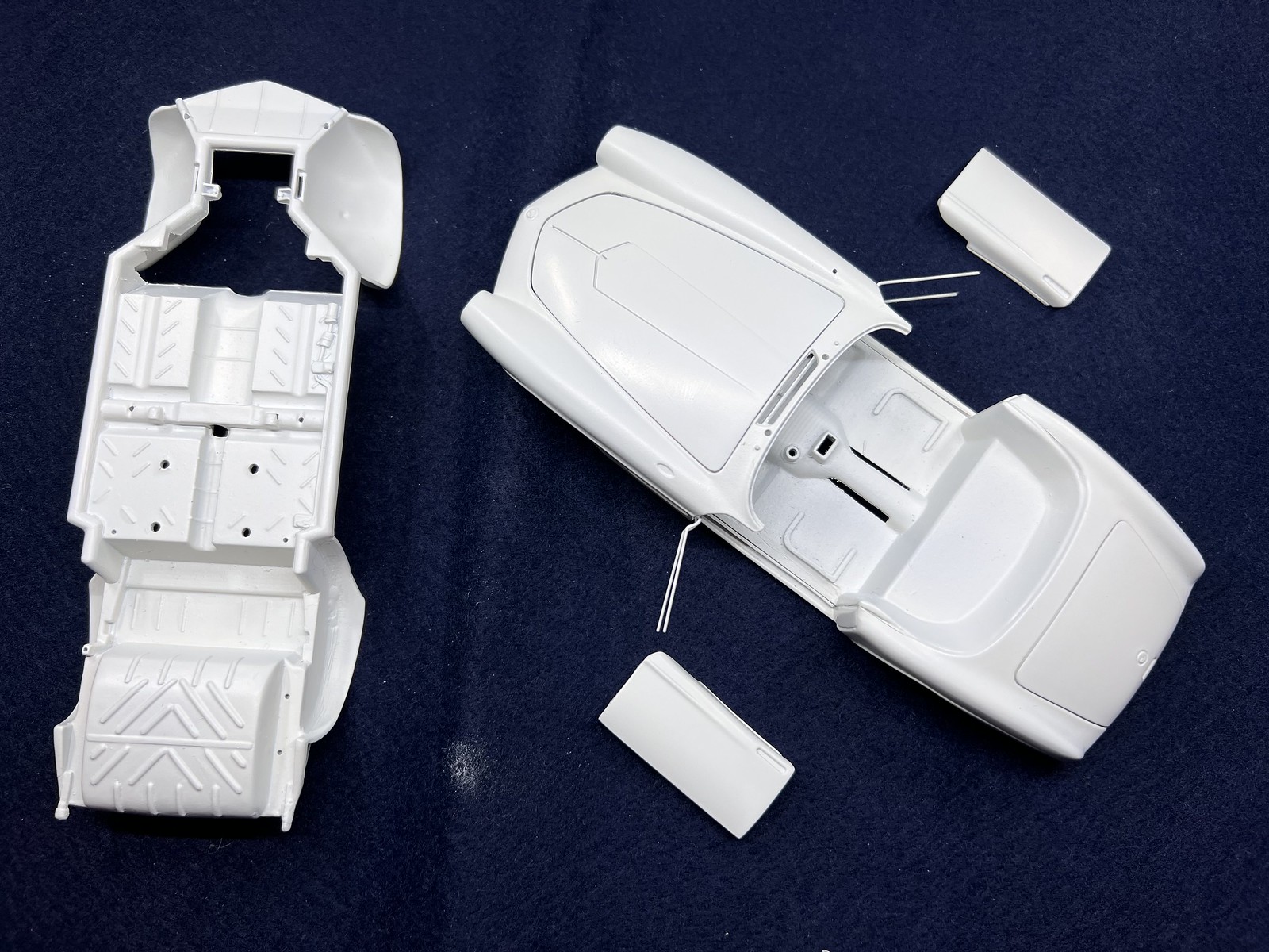
And painted Pearl white 2 copies of the dashboard .
Somes pictures of all that stuffs:
`
Clear coating stage:
I've had to test various varnishes over the Alclad Chrome I sprayed over the inner and outer half-rims and on the nuts, to check whether Alclad Aqua Gloss Clear ALC600 was effectively the one which keeps the best shine .
Unsurprisingly, it is the winner
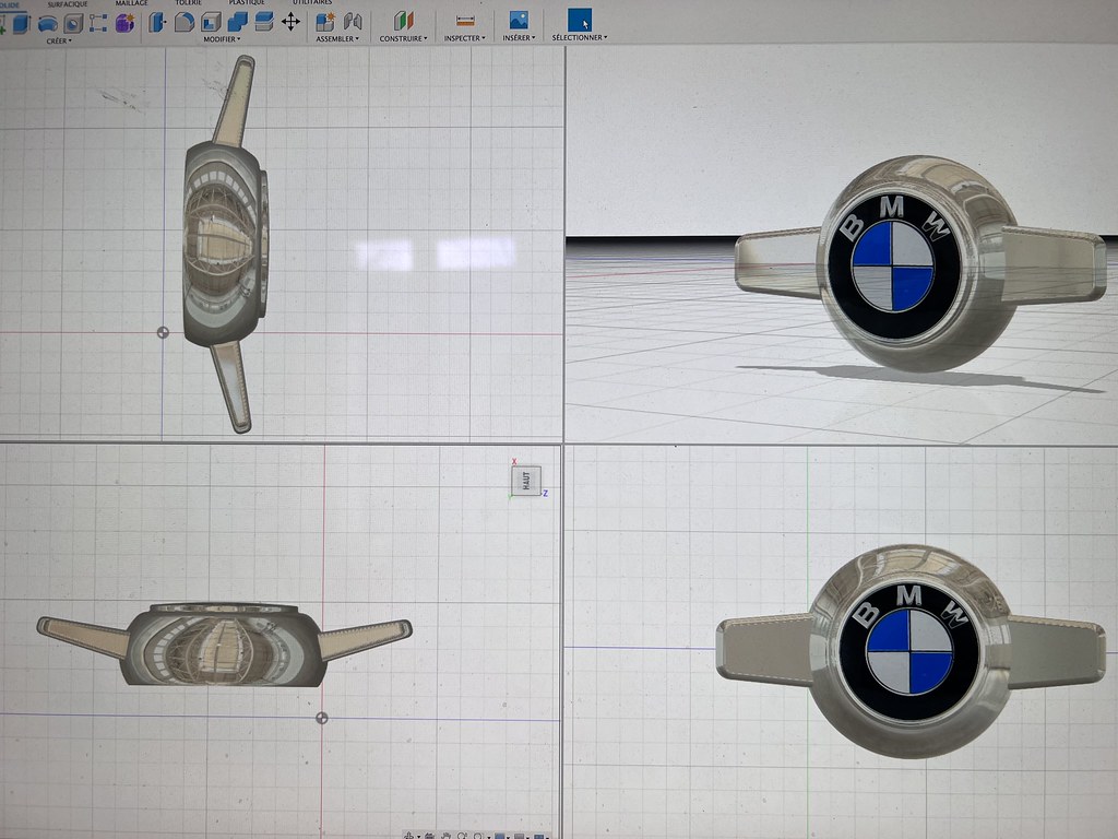
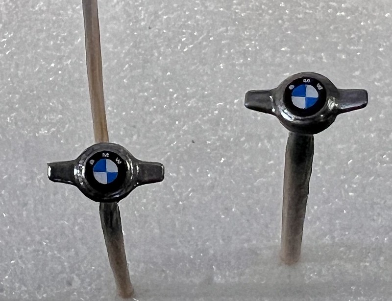
The best 4 knock-off nuts have been chosen and the BMW logo decals applied on them before clear coating.
For the rims, I've used Mr Super Clear Gloss Clear, decanted from the spray can, and then airbrushed. It's perfect for small parts and dries very quickly !
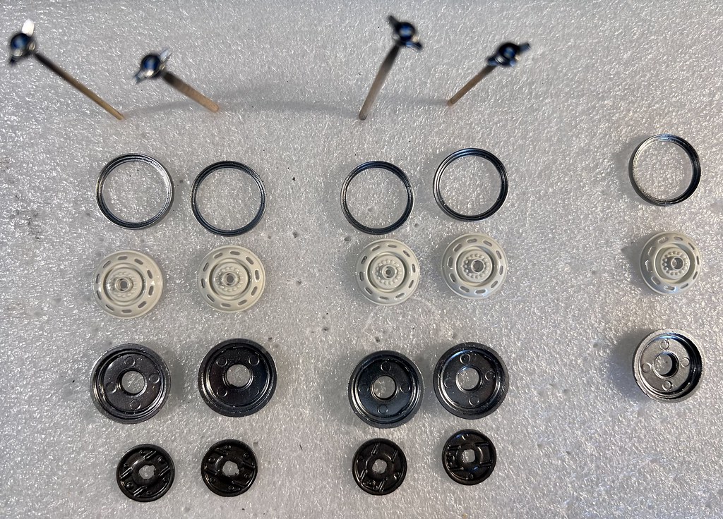
And then, I had to select among 12 sets of 3 pieces, which ones I will keep to assemble 5 rims (4 wheels on axles and 1 spare), each composed of 3 elements.
Not any one is perfect under magnifying glasses, but I manage to find good enough parts for my goal.
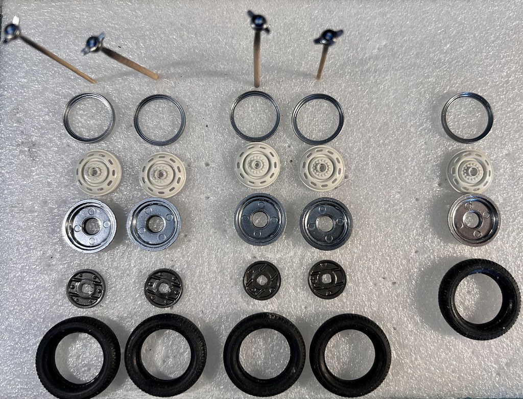
Hereunder some pictures of sets , before assembly:
And I finished then to improve 1 wheel !
I made the inflation valve using:
- a short section of black electrical wire sheath of 0.6 mm outer diameter and 0.4 inner one, that I threaded over
- A short section of 0.37 mm brass wire
- A micro touch-up of the valve's top with Tamiya Rubber Black
The whole set glued in a 0.6 mm hole drilled on the outer half-rim's periphery.
I was inspired by this picture of Elvis' restored BMW:
And my interpretation:
The knock-off nut hadn't been glued yet. This would be done at the very end, and a drop of UV clear resin would be added to the BMW emblem to enhance its shine.
Wheels now achieved ?
I will now continue with the dashboard and the varnishing of the body parts... stay tuned if you like ?
-
 1
1
-
-
On 10/29/2024 at 5:54 AM, slusher said:
Absolutely Stunning!
5 hours ago, Kah puts said:Primo work on this build ??
47 minutes ago, beeRS said:Truly a masterpiece. I followed the build thread with interest. It’s great to see it finished. The result was well worth all the hard work.
40 minutes ago, Roger U said:Beautiful model. Nice clean work.
Thank you guys for your great comments.
I started a build thread on this forum, but have been too lazy to continue!
I'll try to complete it ...
-
15 hours ago, Greasefinger said:
As previous members have said, absolutely great micro-engineering! Have you by any chance seen the real thing in the BMW museum in Munich? I had an opportunity to visit the museum last summer and as I was following your thread in another forum I of course had this in mind when wisiting.
You were very lucky to have this opportunity.
I've planned to visit the BMW museum in Munich and the Mercedes-Benz's pointe in Stuttgart/
Thank you very much for your huge praise ?
-
 1
1
-
-
Thank you so much guys for your kind praises ?
-
19 minutes ago, Hard_2_Handle_454 said:
Very Nice! I've been wanting to get a 2nd one, but they're very hard to come by now. I was lucky to find my first one at a good price.
You were very lucky indeed!
I needed two kits to make this model, due to the drastic plastic surgery the bodies have undergone, and a third would have been welcome
-
You were very lucky indeed!
I needed two kits to make this model, due to the drastic plastic surgery the bodies have undergone, and a third would have been welcome
-
28 minutes ago, Jim B said:
Beautiful BMW. Fantastic work.
Thank you so much, Jim ?
-
4 hours ago, XYHARRY said:
Very impressive build there Thierry, really well done and a fine tribute to the King.
Cheers,
David. ??
Thanks a lot, David ?
-
When I started working on this rare old REVELL 1:24 kit, excited by the press articles and videos of the restoration of Elvis Presley's BMW 507 by BMW between 2014 and 2016, I hoped to make a faithful reproduction and, to be honest, I didn't know that I was embarking on a real adventure, if not dangerous, at least full of surprises, both good and bad, that would test my nerves and patience to the limit!
And this saga lasted almost 2 years, because real life isn't just about modelling.
In total, I spent more than 600 hours on this model, not only studying the 'official' documents, designing, drastically modifying and assembling the body, but also designing and 3D printing the many parts that were added or modified.
The REVELL kit contained only 167 parts including decals; my model now has more than 500 parts and barely 30% of the original parts remain.
You can't imagine the emotion I felt when I finished the model by fitting the canopy.
I think it was surprisingly as intense as when my first granddaughter was born almost 7 years ago!
I dedicate this model to the memory of the King and all his admirers.
Here is a selection of photos. Sorry, but the bodywork is not as clean as I would have liked. I was so afraid of damaging it when cleaning it that I didn't do much.
And now a little video:
I hope you enjoy this model as much as I enjoyed to building it
-
13
-
-
Evening gentlemen
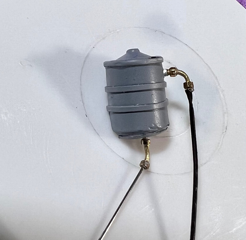
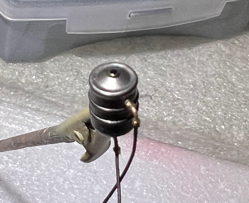
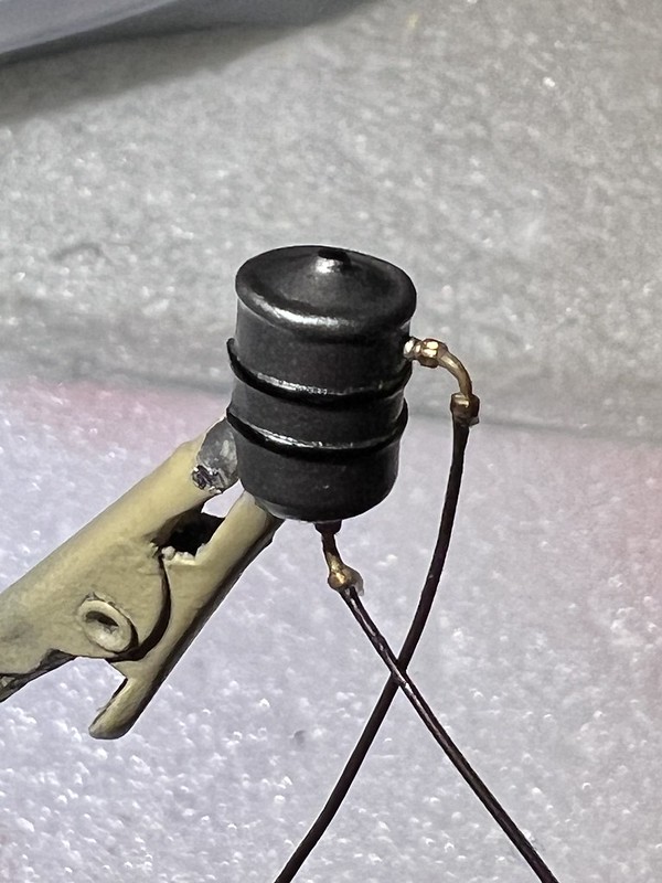
Improvement of the water expansion tank
The kit part:
Mine, after having added a few bits of thin styrene sheet and after priming :
- 1 superior strip (0.5 mm wide) to increase the diameter of the lid
- 2 strips(0.6 mm) on the middle of the tank, which simulate the routing collars
- 1 plate to close the tank at the bottom
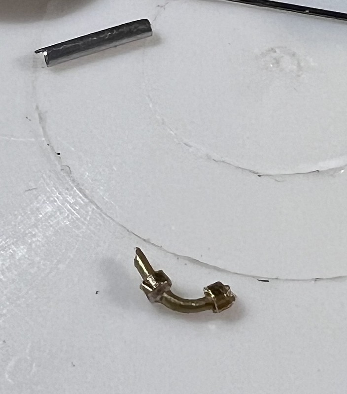
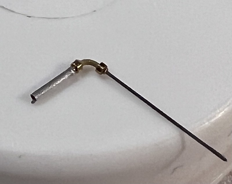
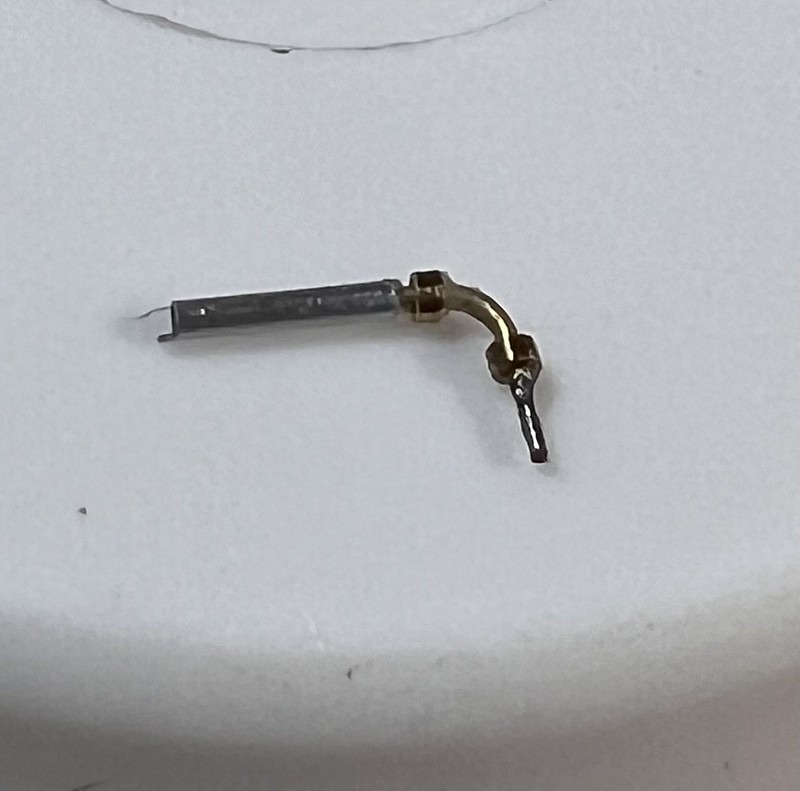
Obviously, an expansion tank has 2 hoses,for entry and exit, one at the top, and the other at the bottom.
I've taken inspiration of these pictures, the left one from Elvis restored car, and the right one from another one:
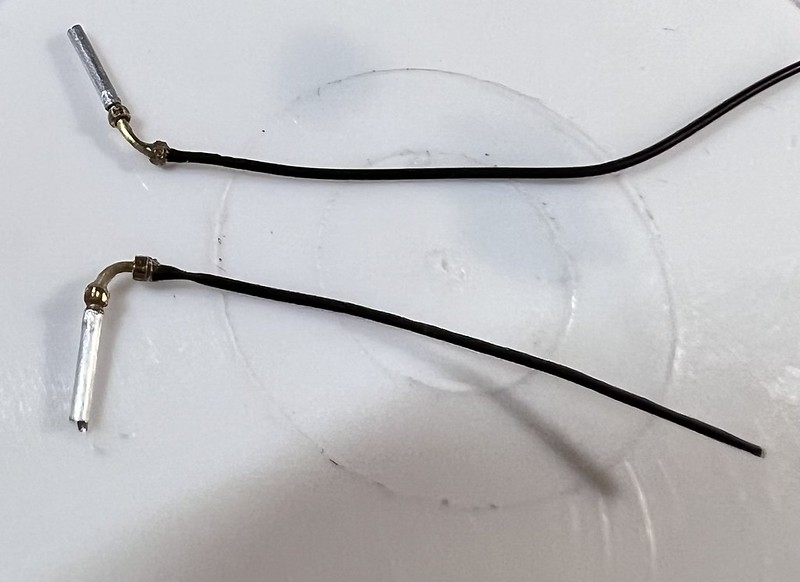
And have machined the superior and inferior hoses and connectors, using:
- 0.5/0.3 mm diameter brass tube .
- 0.3 mm steel wire
- Two micro-bolts: 1.0 mm head, and 0.6 mm thread, that I've re-drilled to 0.6 mm
- some 0.8/0.6 mm aluminium tube
- 0.5 mm electrical cable of which I only kept the plastic sheathI proceeded as follows:
- bended a short section of brass tube,
- threaded and glued two bolts on it,
- inserted a short section of 0.3 mm steel wire at one end,
- threaded the plastic sheath on the steel wire
- inserted the free end of this set into the hole of the aluminium tube
And hereunder is a close view of water lines
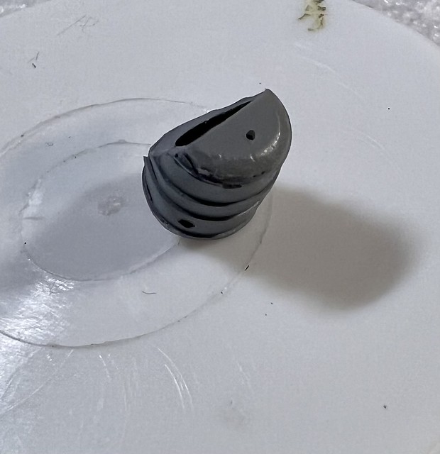
After painting:
While the paint of the the expansion tank was drying, I've fabricated the file supply line which comes from the rear of the car and is visible in the engine bay
Ì used:
- 0.4 mm Ni-Cr wire
-3 brass bolts 0.6 mm as previously
- a short section of 0.6 mm brass tube
- A thin strip of Hasegawa Mirror Finish for simulate the collar
- And after market silver braided line 0.8 mm (0.6 mm would have been more adequate butI didn't have it, so...)
I took inspiration of this picture:
My interpretation:
Fuel supply and expansion tank installed in the engine bay
It is now time to move on to more serious matters, so, stay connected ?
-
1
-
-
Morning gentlemen
A lot of work on this since my last post.
The chassis has been clear-coated, semi-gloss on the whole underbody but the trunk, and gloss on the inner and outer sides of the wheel arches and the underside of the trunk.
Don't take in account the molding marks in front of the radiator and on the top of wheel arche"s...they will be hidden once the assembly is done !
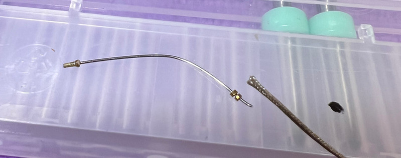
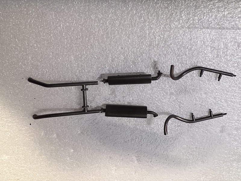
I began to paint and assemble the exhaust lines, and the rear axle.
A little bit of weathering remains to do on these.
The transmission shaft has been painted (gloss black) and is temporarily put in place, waiting to be glued on the rear of the gear box, at its front end, and to the differential housing at its rear end.
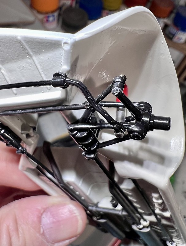
About the rear axle, it remains to to add the shock absorbers, but those supplied in the kit are ....how could I say it ?.... awful !
So I decided to scratch them:
- A 3D designed and printed part for the upper part
- And a true metal stuff for the lower: I haven't decided yet whether it will be a nickel-plated brass rod, or a polished and varnished aluminium one. I"ve to sleep on it !
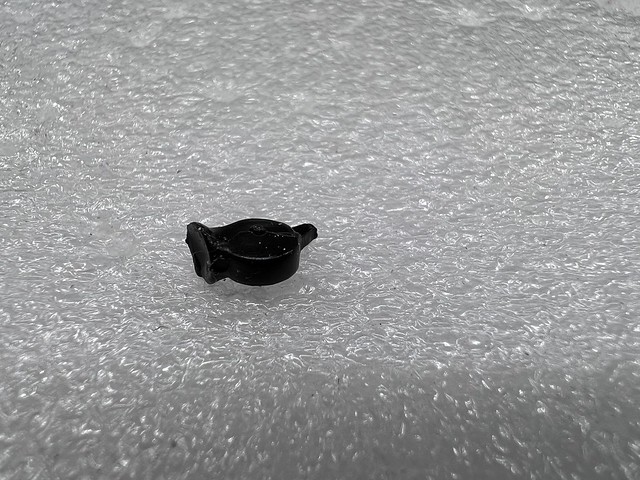
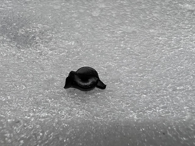
The horns supplied in the kit, that have to be glued on the front of the radiator, are very bad pieces of ugly plastic, twisted and unrealistic, so;, I designed them as well !
The kit part:
My 3D one:
At least, the radiator has been modified, by the addition of a very thin piece of mesh on both sides
A little bit of progress with the completion of the rear axle.
Finally, for the shock absorber's pistons, that must look like polished steel, I decided to scratch them with a rod of brass, that I nickel-plated, and they look great, even if their is a bit low (1.0 mm instead of 1.3 on the kit part)
The upper resin part has been painted red and gloss clear coated.
The horns have been primed and painted semi-gloss black, and are now glued in place in front of the radiator .
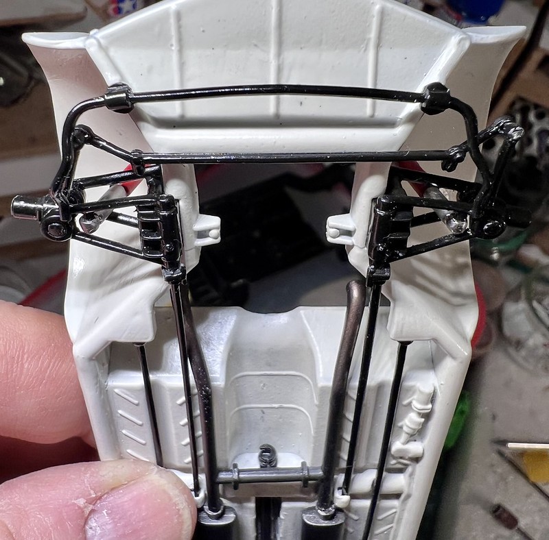
The front shock absorbers are those of the kit, but have been enhanced with some painting:
I used a very nice chrome (Gravity Color Mac Laren chrome set), sealed with Alclad Aqua gloss
Front axle assembly achieved, not without a lot of difficulties, since the instructions are very poor, and the drawings not explicit.
But it's done, and it works
It remains to give the front axle a little bit of weathering, because the restored car has already be driven on several roads, and I'll use some road dust pigment and polished metal pigment to highlight the reliefs of the axle components.
Of course, it will be done at the very end of the build.
The chrome exhaust tips still need to be made.
The parts supplied in the kit are of poor quality, incorrect size and are solid, whereas tube is required.
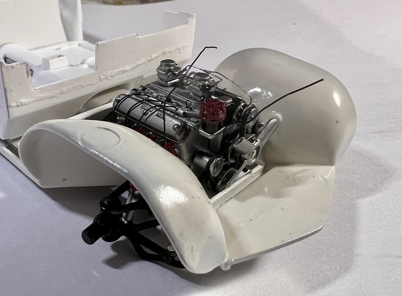
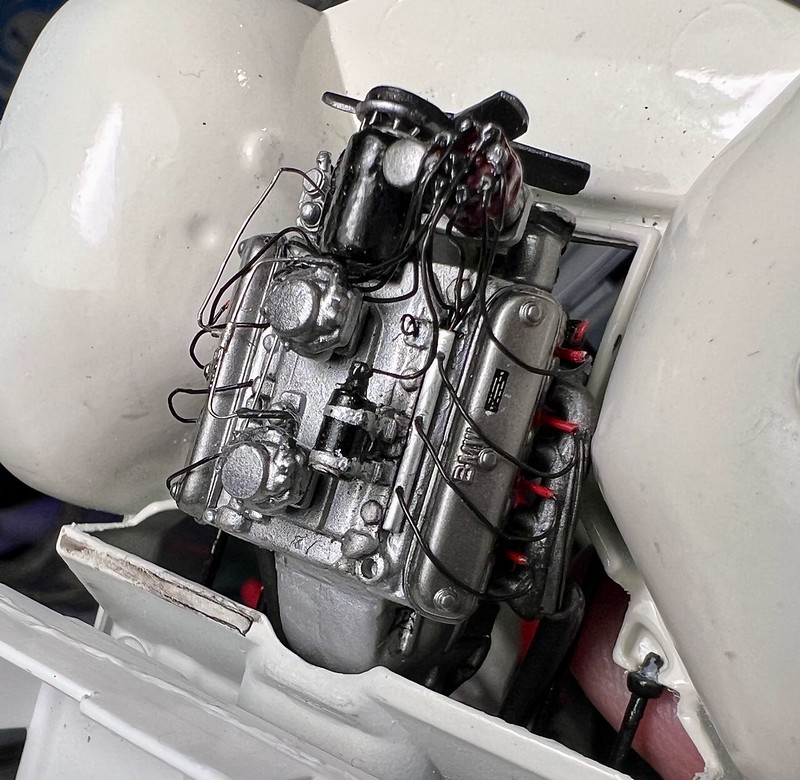
They will therefore be turned on the the lathe in brass rod, then nickel plated.The engine has been placed and glued in the chassis, and of course connected to the transmission shaft.
Don't pay attention to the dust and stains on the bodywork at wheel arches level, I know I've to tidy up the engine bay !
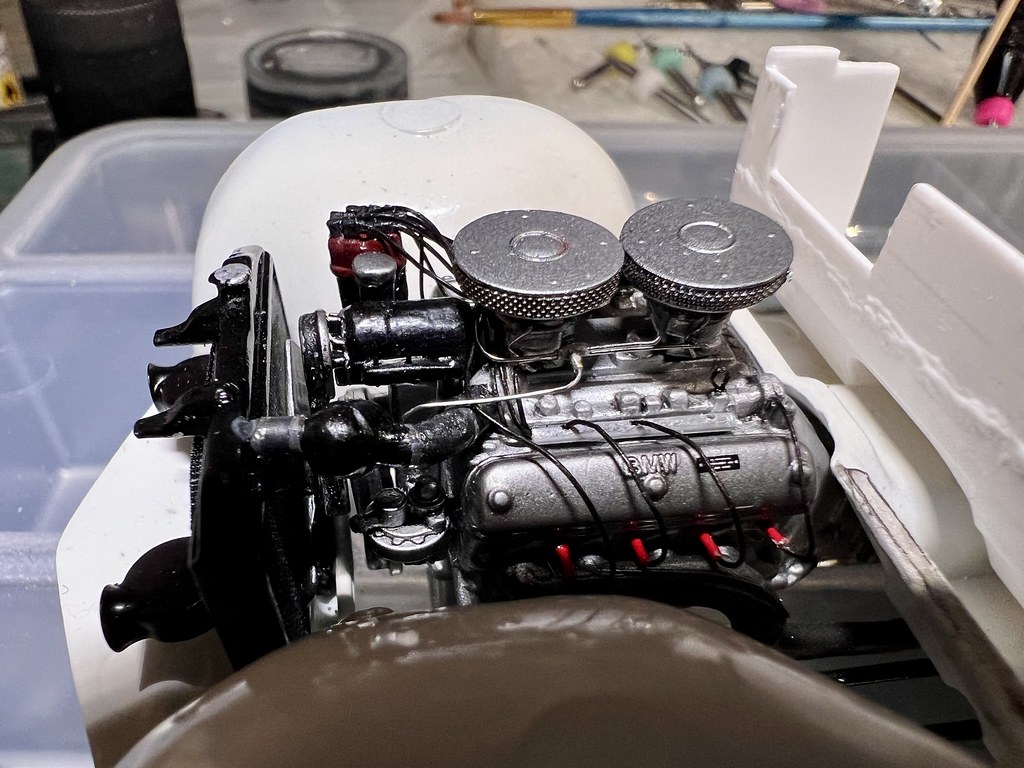
I've tried to make a test fit with the radiator and it appeared that it's not possible to position it vertically for two reasons:
- one: the fan is too protruding and hit the rear side of the radiator
- two: the lower edges of the radiator hit the wheel arches, what prevent it as well to set verticalSo, I've had to make a delicate surgery:
- cut off the fan, and decrease the thickness of its hub, on the rear, from about 1 mm
- trim out the lower edges of the radiatorAnd now, all's OK, or so (on the photo below, the radiator bend slightly forward because it's not glued and the weight of the horns is unbalancing it)
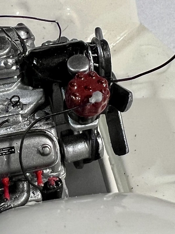
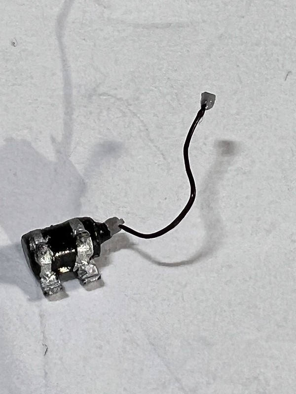
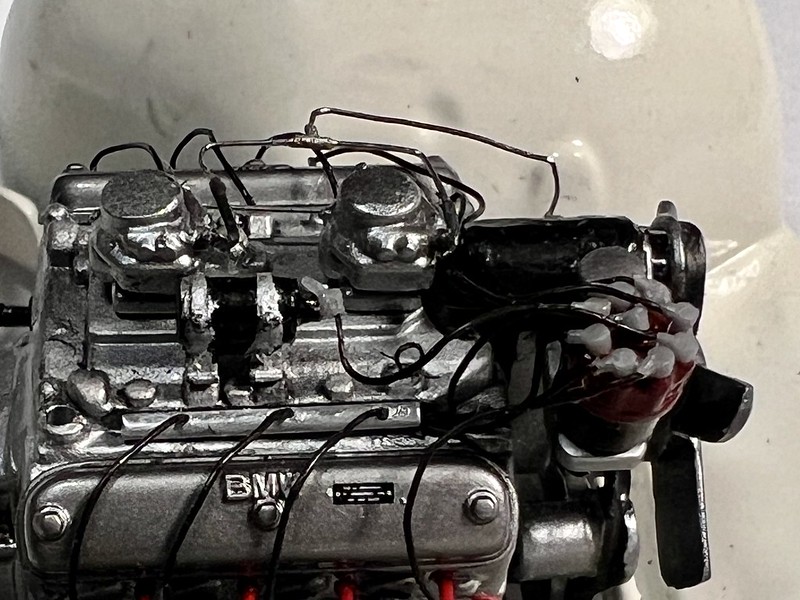
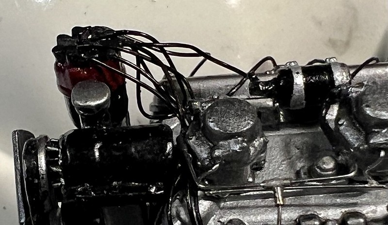
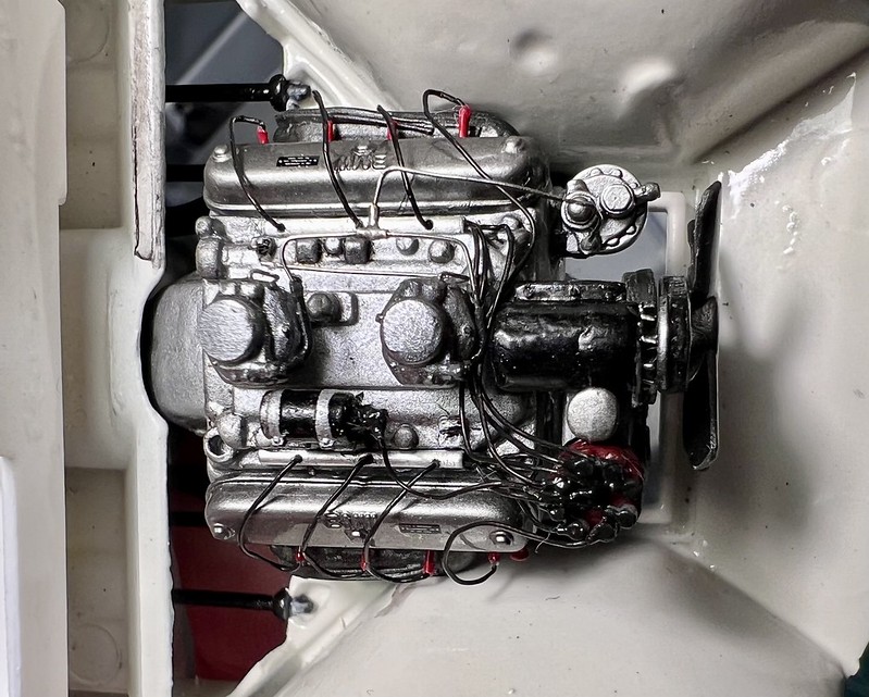
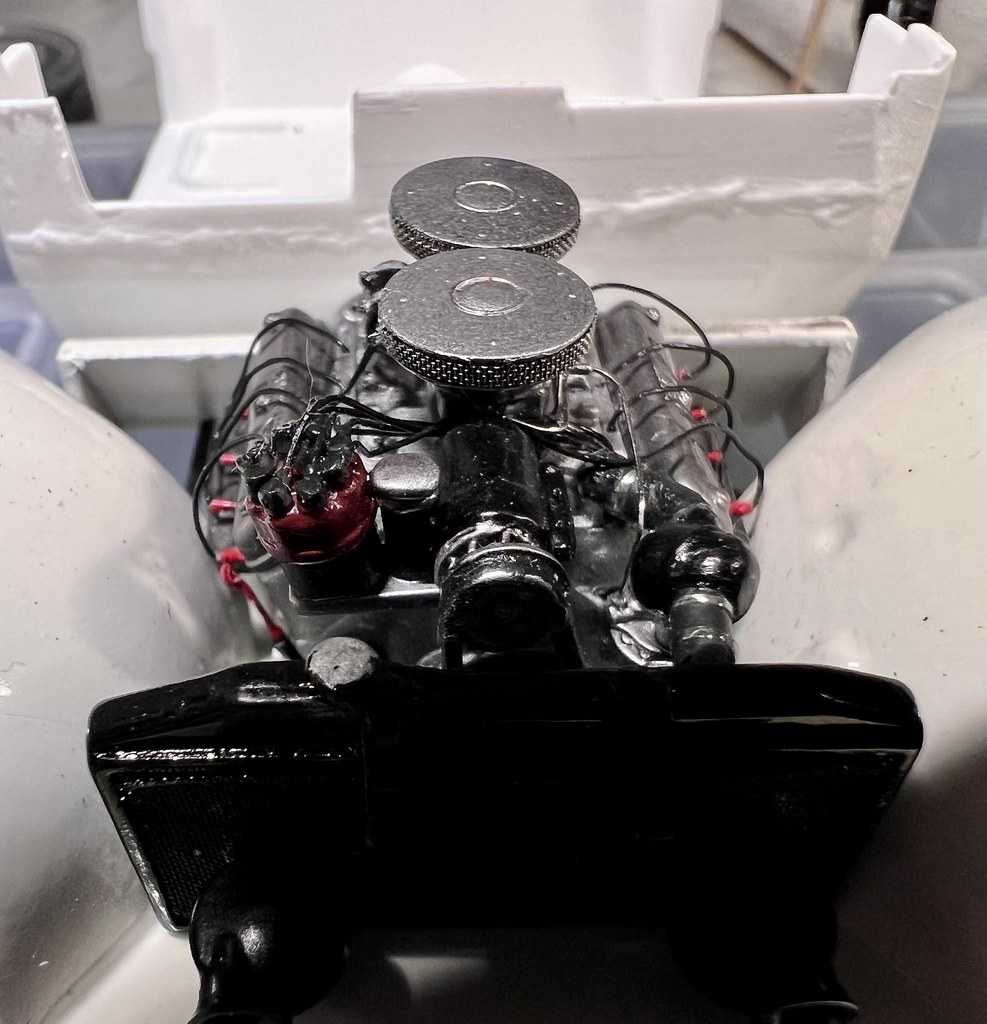
However, the radiator won't be glued immediately, because my hands need room to place easily my tiny spark plugs and their wiring !I've spent no less than 5 hours to place correctly the ignition wiring !
Not less than 8 spark plugs connected on the distributor, plus the ignition coil plug !
A lilliputian work under magnifying glass, with several pauses in order to calm my tremor !
But it was worth the efforts !
During the process:
Once achieved:
Once painted:
A total of 42 parts were assembled for the ignition system !
She's coming to life !
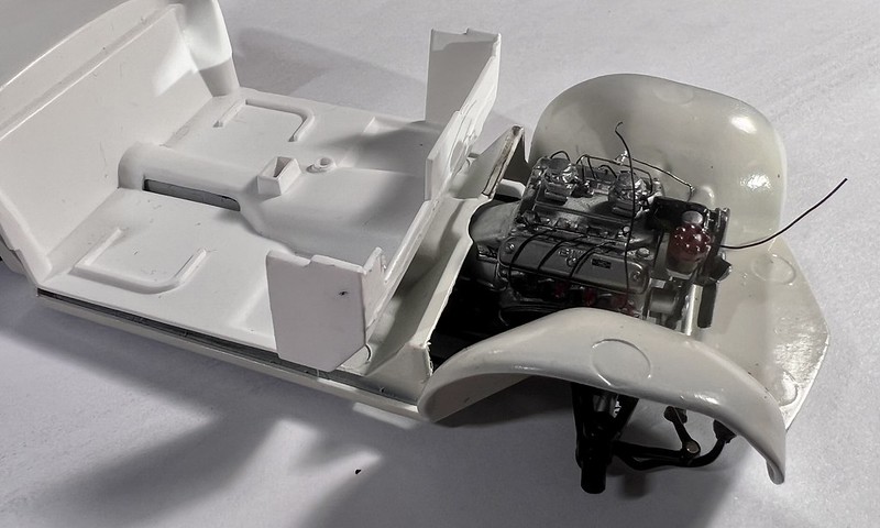
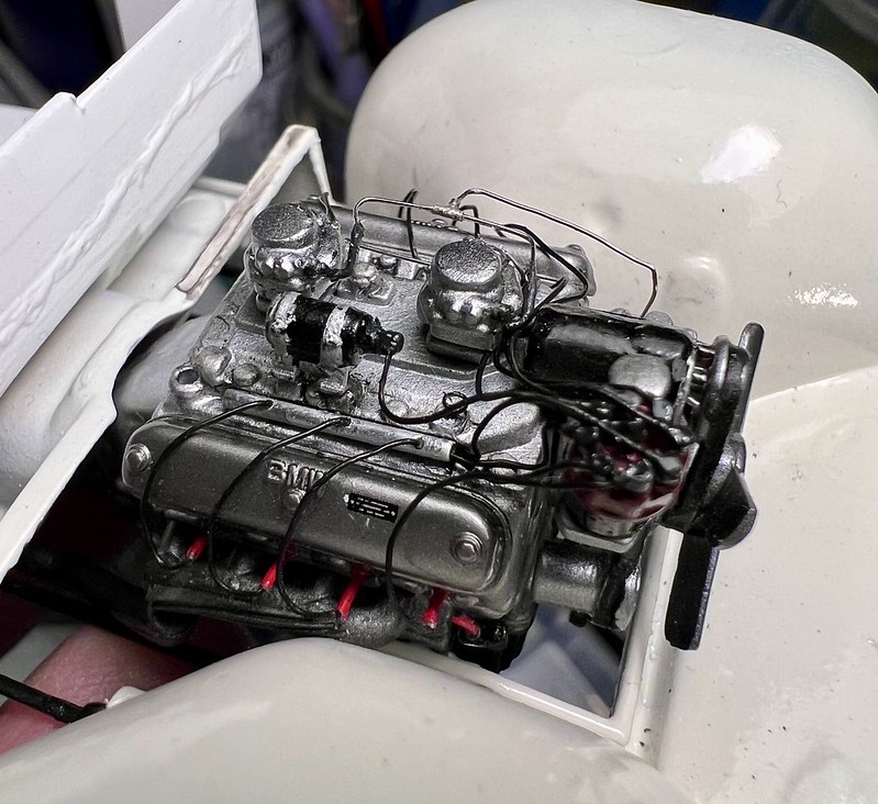
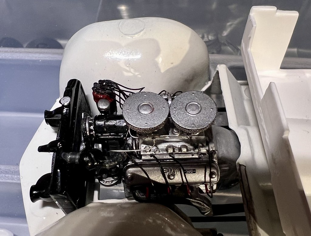
I've spent a few hours today to prepare, paint, and improve a single part: the water cooling upper duct.
It consist in 2 rubber hoses separated by a roughly spherical piece, connected, on the front to the radiator, and on the rear to the engine block
The whole part was too large to fit correctly between the engine and the radiator, and I've had to make some surgery.
The rubber sections have been painted rubber black, and the middle part semi-gloss black.
As on the true car, I've added fastening collars, 2 on each rubber section, made from very thin strips of Hasegawa Mirror Finish (about 0.5 mm wide).
Not an easy job on a painted tiny part.
I'm not absolutely happy with the result, but you know that I'm too much perfectionist.I've as well decided to modify the carburetors fuel supply lines, because the angles of the lines were too sharp, and I wanted them rounded.
A delicate and tedious job, but it was worth the pain.
At last, I've glued in place the air filters
Don't think the job is over!
There are still a lot of things to install in the engine bay and under the bonnet:
- first of all, the expansion tank and its hoses
- but also the fuel inlet pipe and its connection to the filter
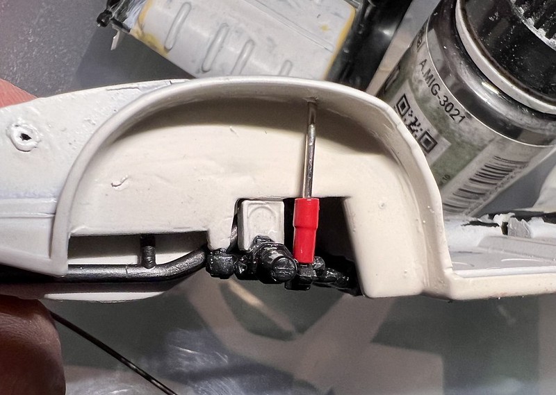
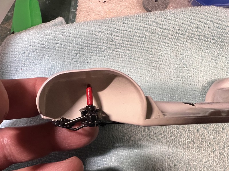
- the steering,g mechanism
- and several pipes, once the firewall, currently attached to the body, will be in place ... and this is not for tomorrow!
- and all the rest, which I will spare you the enumerationI leave France on Thursday and don't know what I'll be able to make on this model during the 2 next days, but stay tuned, if you like
-
1
-
-
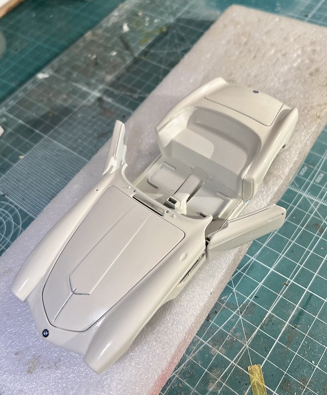
Morning guys
As promised, here is the result of my painting job for Elvis BMW 507's bodywork
I do think the final color is very close to the original white pearl it arbors since its restoration , the same color as it had when Elvis bought it.
I've been very surprised when I placed side by side my damaged and unpainted plastic body and the painted one, because in day light, the colors are very similar
It remains now to give it some layers of gloss clear coat.
This will be done in a few days.
And then, the assembly will be able to go ahead
-
On 11/27/2022 at 4:02 PM, Pierre Rivard said:
Travail magnifique Thierry,
Always inspirational and a bit intimidating looking at your craftsmanship.
I just spent hours reviewing your Moss SLR w.i.p. on BritM because I want to learn before I tackle mine (thinking to do a Fangio conversion). If I can achieve 10% of your detailing magic I will be very happy!
Thank you for sharing your work.
Merci Pierre
Thanks a lot ?
-
Thanks guys for your kind compliments ?
-
Incredible result on this one ! I could swear this is the real one !


![BMW 507 elvis - [REVELL] BMW 507 cabriolet 1958, ayant appartenu à Elvis PRESLEY (base de 1991) Réf 7200 52231629796_69932b448a_c](https://live.staticflickr.com/65535/52231629796_69932b448a_c.jpg)
![BMW 507 elvis - [REVELL] BMW 507 cabriolet 1958, ayant appartenu à Elvis PRESLEY (base de 1991) Réf 7200 52231893159_bdf580bebb_c](https://live.staticflickr.com/65535/52231893159_bdf580bebb_c.jpg)


![BMW 507 elvis - [REVELL] BMW 507 cabriolet 1958, ayant appartenu à Elvis PRESLEY (base de 1991) Réf 7200 - Page 2 52372535165_7bc88a0b27_c](https://live.staticflickr.com/65535/52372535165_7bc88a0b27_c.jpg)
![BMW 507 elvis - [REVELL] BMW 507 cabriolet 1958, ayant appartenu à Elvis PRESLEY (base de 1991) Réf 7200 - Page 2 52381284909_a4378b39ca_c](https://live.staticflickr.com/65535/52381284909_a4378b39ca_c.jpg)
![BMW 507 elvis - [REVELL] BMW 507 cabriolet 1958, ayant appartenu à Elvis PRESLEY (base de 1991) Réf 7200 - Page 2 52380974216_d1b9f7881a_c](https://live.staticflickr.com/65535/52380974216_d1b9f7881a_c.jpg)


Marvel's Hydra coupe 1/12 scale full scratch build
in WIP: Model Cars
Posted
Dropped my jaws on the floor, again ! 👍