BigTallDad
-
Posts
1,526 -
Joined
-
Last visited
Content Type
Profiles
Forums
Events
Gallery
Everything posted by BigTallDad
-
I recently finished the model; started with the '93 Mustang Cobra kit. Changed the rear spoiler, got wheels from the '91 convertible kit, replaced the Cobra side emblem to the scratch-buit 5.0 ,scratch-built the cover for the cargo area, filled in the grill, wired/plumbed the engine, used the '91 taillights, added the brake cooling scoops (non-functional, just like the 1:1), scratch-built and tinted the moon roof, and painted those tiny MUSTANG letters on the rear quarter glass (they are less than 1 mm tall) This is my original 1:1 The model of it Not the best quality photo; the model is attached to a clear base, so I just shot thru it
-

Best stock early flathead?
BigTallDad replied to OldNYJim's topic in Model Building Questions and Answers
What about the flattie from a '40 Ford? The Revell kit has a nice engine, although the radiator hoses are not quite correct. -
Quite by accident I discovered that vinyl insulation on electrical wire has a “memory”; if stretched, it will revert to its original size after the stretching implement is removed. Here are the components of a plug, the boot, and the plug wire. I used .030” styrene rod for the plug, and eyeballed the size for the boot and the wire. Note that the boot is slightly larger than the wire and the plug, but the inside diameter is still too small to insert the styrene and wire. I used a common push pin as a stretching tool. Place the boot on the point of a push-pin, stick the pin into an eraser or similar material (corrugated cardboard works very well too), then work the boot to the thickest part of the pin. Although I'm only showing one boot, several can be placed on a single push-pin. I discovered (the hard way) that you need to let the pin do the stretching for at least an hour; the longer the vinyl stretches, the longer it takes (within reason) to return to the original size. If you only wait a few minutes, the vinyl shrinks almost immediately and you’re back to square one. I set the stretched version on the sample to give you an idea of what the stretching will do. Note that the boot is larger in diameter (and can be worked with easily) but is a bit shorter. Don’t worry, when the almost-original diameter returns, the length will too. Place the styrene in some kind of clamp (I use a vacuum-base vise). Working rather quickly, remove the boot and slide it over the styrene; place a drop of CA on the end of the styrene, slide the boot over the tip of the styrene (leaving room for the plug wire), and insert the plug wire into the boot. After the boot has returned to the original (albeit slightly larger) size, trim the styrene rod to the desired length. Use a number 68 drill to drill the holes for the plugs and cement the plugs in the holes, leaving a portion of the white (to represent the porcelain on the spark plug) exposed. After all is said and done...
-
Although pre-wired distributors are available, some of us like to do it the old-fashioned way. The tutorial is separated into two sections: making the guide, and using the guide. Making the guide. I used brass tubing, 1/32” and 1/64” inside diameter. With the help of a variable-speed drill and Dremel cut-off wheels, I cut a 1/2" length from each size. Make sure the lengths are equal! It is important to keep the length of the guide short; otherwise, a longer portion of the drill bit is exposed which increases the chances of breaking the bit. I then inserted the 1/64” into the 1/32” tubing, with just a hint of the 1/64” protruding and soldered the two pieces together. The protruding 1/64” tubing will cause a small cup at the other end of the guide, thus the 1/32” tubing will be used to fit over the distributor nipple. Next, I put a #78 (or so) bit in my pin vise and, using the guide for reference, set the depth of the hole. Using the guide. I prefer medical tools (such as hemostats) to hold the guide, since they have the ability to lock. Make sure your holding device has “teeth” that grasp the guide, otherwise the dreaded “Ping, I wonder where it went” syndrome will rear its ugly head and you’ll need to make another guide. Needle nose pliers, with strong rubber bands around the handles, will also work. I used double-sided masking tape (as used in putting new grips on golf clubs) A LOT! In this case, the tape is placed on a popsicle stick and the stick is locked in a small, vacuum-base vise. The distributor cap is then placed on the tape. Since one hand will be holding the hemostat and the other hand will be operating the drill, stability of the distributor cap is very important! Place the 1/32” end of the guide, insert the drill, and drill away. Remember, we’ve already set the depth of the hole in a previous step. For photographic purposes, I darkened the hole with a lead pencil. As you can see, the hole is centered and is of the desired depth. While this might not be everybody’s cup of tea, it certainly works well for me. If you find the #78 drill is too small, use it anyway, then graduate to a larger drill. The previously-drilled #78 hole will act as a guide for the larger bit and maintain centering.
-
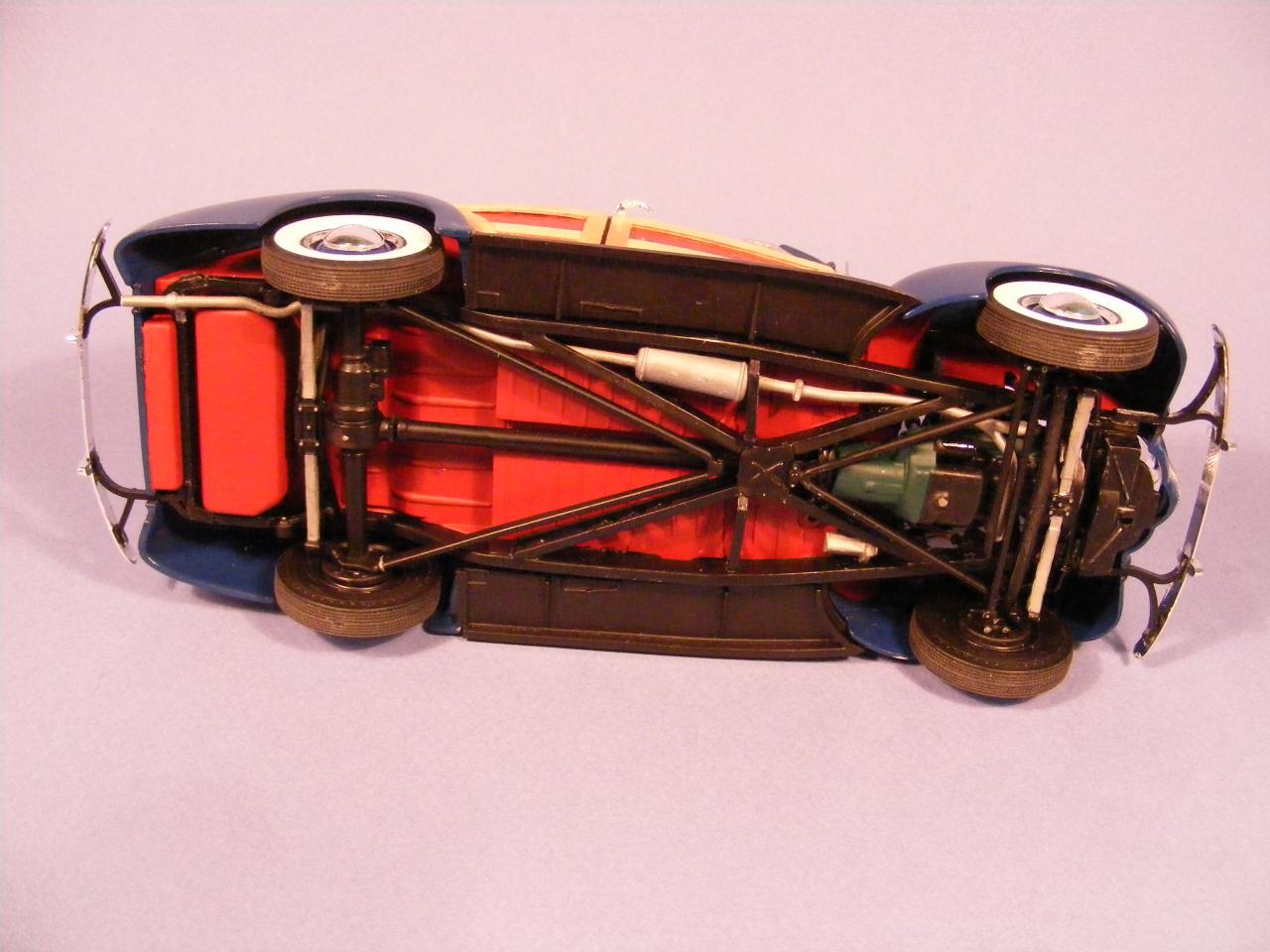
In response to the comments... Harry, you're shooting the messenger LOL. I didn't pick the wheels/tires, the owner did. The chassis is the typical molded-in AMT variety, carefully painted The colors are shown on the 1:1 below
-
Years ago I had a Dakota and I finally got around to build a model of it. I started with a Lindberg snap kit, and I was very surprised at the quality, and level of detail. Although everything on the chassis is molded in (ala AMT) the details are crisp and plentiful The wheels are attached to the sprue in the center of the rim (which is covered by the tire) therefore there are no little nicks on the edge of the rim. The tires do not have the customary ridge in the center of the tread pattern. I've never seen tires/rims treated in this fashion, and I was amazed that they were in a snap-kit! Perhaps the other model makers can learn from this. Here are some shots of the completed model. Remember, this is a curbside kit, so there are no engine pictures. The tonneau cover is scratch-built (does not come in the kit).
-
My son is the foreman at a local auto-repair shop; last year his boss (the owner) bought a ’66 Mustang and the two of them did a restoration job…lots of new panels, a hood scoop, and a fresh engine/tranny combo. I found the AMT kit at a model show and built it to match the 1:1. The actual color is more of a metallic maroon; the lighting makes it appear somewhat red. I used the left-over paint from the real car, so the match is exact. The tires came from the MPC SVO Mustang kit and I found the wheels online. The wheels/tires are an exact match to the 1:1, even down to the wider wheels/tires on the rear. The engine is a 302 block and a 351 crank, resulting in an ultimate displacement of 347. The camshaft is insane, with so much duration that there is difficulty building vacuum for the power brakes. I found the valve covers online, but the lettering was in black. A pixel-by-pixel replacement resulted in the red decals. On the 1:1, the original master cylinder was replaced with a dual master cylinder, so I had to scratch-build one. The bracing in the engine compartment was not included in the kit, so that too was scratch-built. Also, take a close look at the graduated tint at the top of the windshield. I just had to show off the vanity plate! I used a silver PRISMACOLOR pencil to highlight the smaller lines, and I highly recommend it. If you have an oops you can wash away the error with a small paint brush and window cleaner.
-
I had considered using styrene rod, but liked the way the pattern matches the 1:1 welting. The thread also conforms to curves more easily, and there is no sanding involved.
-
Regarding the welting, I just (a few minutes ago) added a tutorial called "Another use for thread" I'm still learning how to function on this site and hope this link will take you there directly. http://www.modelcarsmag.com/forums/index.php?showtopic=101745
-
When I built it, I found that the rear fenders are separate from the body and need to be glued on. No matter how I fussed and fiddled with the alignment, there's still a gap. Here's a shot of the fender/body gap on the model. Here's a shot showing (for photographic purposes) the white thread I'm using. It's Button & Carpet, 74% synthetic and 26% cotton. The cotton lends itself to magic markers as well as Elmer's white cement. After coloring with a magic marker, run the thread through some Elmer's white glue and wipe off the excess. Using a doll-house clothes pin, secure one end then push the remaining thread into place. Here's what it looks like after the glue has dried and the ends are trimmed off. Any excess glue can be removed with a swab and Windex. The final results. This will look great under some Tamiya TS-13 clear.
-
I was recently in Rodeo Shack and saw some circuit board for experimenting. The board had a LOT of small, evenly spaced holes. After buying one (less than ten bucks, if I recall) and scrounging up some scrap lumber, I came up with this. The bottom was deliberately left longer so I can clamp it to a work surface. As I said, there are a LOT of holes. There is a hole in the back for my shop vacuum; the hole in the front, in combination with the gate, allows me to lightly hold part in place whilst heating it with a heat gun (from Harbor Freight). When the plastic is soft enough to form, close the gate and let the vacuum do the rest. For forming smaller pieces, cut a hole in some aluminum foil and continue to march.
-
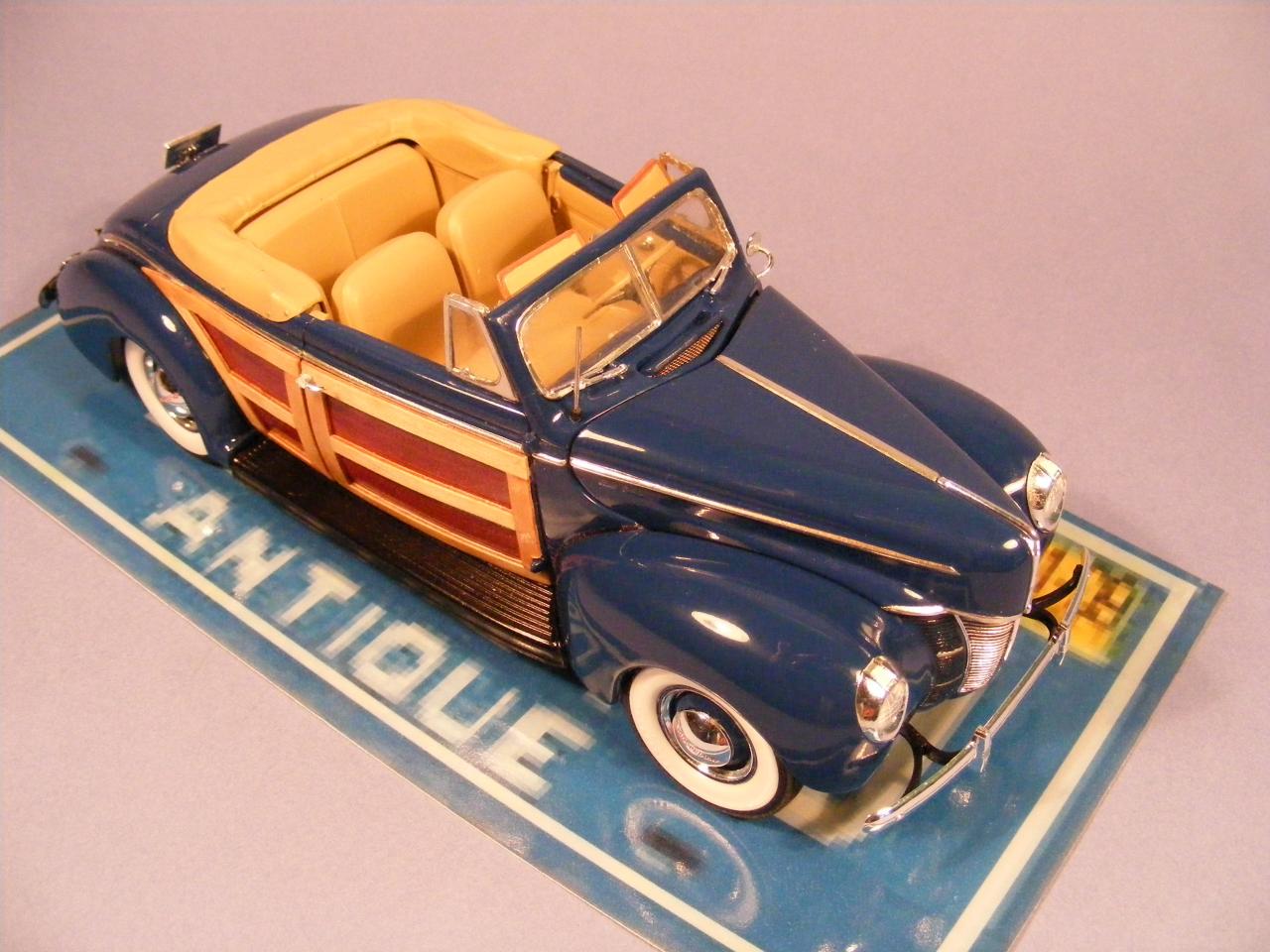
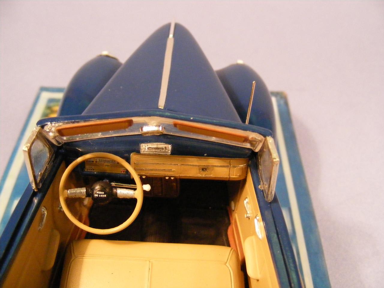
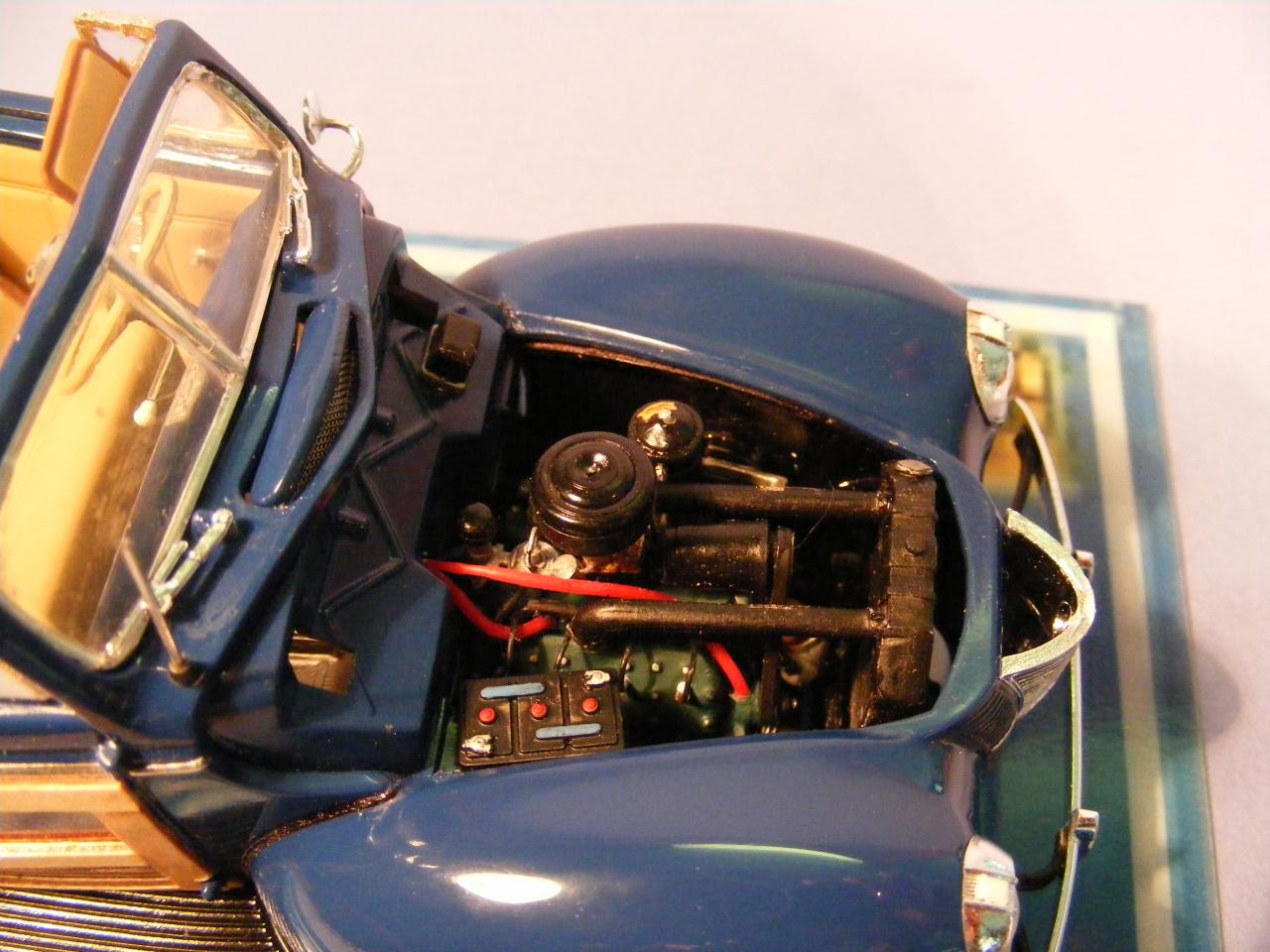
Thank you for the nice words! Bear with me while I learn how this site operates. Just for some background info... The dark wood siding is a decal. but the light siding is 1/32" plywood, all hand-cut and hand-fit The fender welting is thread The open fresh-air cowl has a screen, just like the 1:1 The antenna, kick-panel courtesy lights, plug and wires (as well as the tube), fuel line, and sediment bowl are scratch-built. As others have mentioned, I'm a member of another forum (that might change soon) and in the process of bringing info from that area to this one. If there is a lot of interest in the wood process, I'll put that at the top of the list.
-
This is my first post, so be gentle..

-
I got this website from SmellyFatDude, so I thought I'd give it a try.