Peter Lombardo Posted January 12, 2008 Posted January 12, 2008 This is an update on the progress I have made on the 68 Sunray Corvette, but really, I wanted to post some shots of how the dashboard on the Sunray is being fabricated. First things first…. The engine has been completed and dropped into the chassis. I have obviously wired the sparkplugs and set in the main oil line and the beginnings of the brake lines. I will be adding all of the small electrical wires next as the dashboard, dash bar support (driver side) steering wheel and gages go in. One point of interest, I fabricated the trans. linkage for the transmission. The kit transmission has the linkage molded on and since it is not seen very well, it is good enough...but on this "cutaway" model, it is in plan sight. I cut off the molded linkage and then sanded it smooth. I drilled out the area where the linkage attaches to the trans. I cut out of very thin plastic the two"oval" shaped connector pieces that go from the linkage to the trans and pinned them to the trans. I fabricated the linkage from thin brass rod and shaped it to fit. I cut the mounting bracket for the shifter out of a piece cut from a coke can and bent it to the proper shape, drilled two holes for the linkage and mounted everything to the trans. The only part left to do is the actual shifter mounted to the unit and it will be good to go. I have mounted the wheels and tires, which only need the Goodyear decal logos installed. The wheels are correct for the car, but the backing rim was all wrong. Revell used a solid backing rim and the real car, obviously would never have that, but the wheel/tire mount to the axle via the back of the rear rim. Using my Dremel tool with a cone shaped grinding stone/grinder, I cut out the center of the rim leaving just the outer rim that fits into the wheel. When this is mated to the front part of the wheel (painted to replicate the alloy mag. wheel from the actual car) it looks like the prototype wheel, and as you can see from the picture, you can now see through the mag. wheel, just like the actual car. But like I said earlier, I had to fabricate a new mounting system for the wheels which is simply Aluminum tubing cut to fit the proper distance, so that the wheel is the correct in reference to the wheel openings. Then this is super glued to the back of the front half of the wheel center and then mounted on the kit wheel hubs. As you can also see, I opened up the front headlight so I can mount “real†headlights, and not use the “decal†headlights from the Greenwood car. It is interesting to me that they make a relatively accurate clear cover for the headlights, but chose to do the lights with decals…I know it is because they did not want to modify the mold, but I still think they should have made the adjustment, oh well, I guess that is left for use guys to do. Not hard to do, I cut through the sides and back of the flip up light cover, along the panel lines. When done. I “scored†the front edge along the panel line, to release the tension on the plastic and allow it to be bent down, then I glued in the back and side pieces and it was finished. The headlights are taller then the opening (made from Alum. tube and MU jewel lenses (HO train items) but the neat thing is how the clear cover is raised to allow the lights under them). The gas tank is roughly painted dark silver, it will get a “galvanized†steel splatter paint job and the filler line added next, along with the tie down straps fabricated from thin strips cut from a coke can. On to the half dashboard, which is the reason for the post… The Greenwood car, which is the starting point, comes with a simplified dashboard. This may be correct for that car, I don’t know or care at this point, but it is not correct for the Sunray car. I took out the dash from the Baldwin Motion Corvette, that I have, and have not built (This car gave up it’s two “stock†seats, one for the passenger seat in this car, and one for the passenger seat in the #29 car I did earlier, as both of those seats are replaced with resin, semi-race seats, thinking that if I owned a Baldwin Motion Corvette, I would have upgraded the seats to ones that could handle the cornering ability and additional power of that car) Anyway, I did not want to lose the dashboard for the Baldwin car, and being that I only need the right half for the Sunray car, a quick molded copy would be the best solution. Now, let me say first off, I have made a number of resin casts from molds I have made, and yes I know the right way to do it…this is not that method. This is a fast and dirty, if you will, one time use mold and copy for a piece that will not be in the forefront of the model and more importantly, is not intricate with lots of “ins and outs†to it. You can see from the photos, I started with a piece of the putty that is supplied in a resin casting kit, used to form a “Dam†for the silicone mold material. ( If you don’t have this putty, just steal some from one of your kids play putty, it will work just as well) I worked it with my hand to warm it up and make it more elastic (important) then I pressed the dash into the putty being sure that it was high enough to cover the sides. Next I mixed up a small batch of Bondo two part putty being sure to have the hardener mixed in very well with the putty. I let the putty sit for about 30 seconds so that the chemicals could begin to bond. Then I slowly added the putty into the mold taking care to try and not have any air pockets in the bottom of the putty where it touched the pattern, female mold part. (try as I did, you can see I have two small pinhole to fill, no biggy) I tapped the mold firmly on the table to help the Bondo settle in, than I layered on the rest of the putty. I allowed the bondo to harden which takes about 15 or 20 minutes, to be on the safe side. Then I carefully began working the putty away from the hardened Bondo. You can see, as it pulled away, little bits of putty stayed with the molded part. I used hot water, soap and an old toothbrush to clean them off. Then I used my Dremel tool with a sandpaper grinding drum to grind off the excess. You can see a black line where I will cut the dash, then fill the two small pinholes with Tamiya body putty, paint it black and install it. It just took me at least three times longer to explain the process, then it took me to do it. So, if you ever need to make some small simple parts, and you need them yesterday, this could work for you. Next up, I will wire the electrical system, prime and paint the body, and build the dash roll bar and install the gauges…P.S. I just stumbled on what I think is a neat way to make a tachometer. I will post that later, assuming it works, with pictures, once I build it. Thanks, and congratulations, if you made it to the end of this post, go to your local hobby shop and reward yourself with a new kit…you earned it.
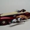
Peter Lombardo Posted January 20, 2008 Author Posted January 20, 2008 This is the final installment before I finish the Sunray Corvette cutaway. These shots were taken over a couple of days, so you can that the Corvette detailing has progressed. The body has been primed and painted with the base white. I will mask off and complete the blue section in a day or two. I needed to replace the right side inner door panel as the Greenwood kit has a flat smooth one, so I went back to the Baldwin Motion kit and made a mold of the door panel out of putty. The white powder you see is mold release powder. As with the dashboard, I molded the door panel out of Bondo body putty. It came out nice, just a few small pin holes to fill, then it was painted black and installed in the interior tub. I mentioned in the last post that I found a nice little way to make a tachometer. For the last few weeks have had a fuse for a string of Christmas lights in my pocket. The other day, when I put my hand in my pocket, I could feel that the fuse had come apart. When I took the pieces out of my pocket, it hit me. The two ends looked exactly like an older style tachometer. I needed one for this Corvette, so it just fell together. I drilled a hole in the side, filled in the center with epoxy, and inserted a rod in the side hole. When dry, I decaled the face, covered that when dry with clear Tamiya paint and the tach. was done. I made the dash roll bar and fabricated the brake bolster support. I made the brake and clutch pedals and connected them to the dash. The clutch pedal connects to the rod that runs to the clutch. I wired the gages and tach. I ran the oil line over to the oil overflow tank on the right inner fender wall. The fuel tank was painted to replicate the galvanized material that the real tank is constructed from. The fuel line is installed and the fuel breather is on top painted blue. I only need to install the fuel filled once the body is in place. The tires finally got the Goodyear logos and I gave them a flat sheen to make them look more realistic. The seat is installed, just waiting for the seat belt which I am constructing now. Once the body is painted, decals go on and final assembly will be completed. Thanks for looking.
Recommended Posts
Create an account or sign in to comment
You need to be a member in order to leave a comment
Create an account
Sign up for a new account in our community. It's easy!
Register a new accountSign in
Already have an account? Sign in here.
Sign In Now