Ognib
-
Posts
784 -
Joined
-
Last visited
Content Type
Profiles
Forums
Events
Gallery
Everything posted by Ognib
-
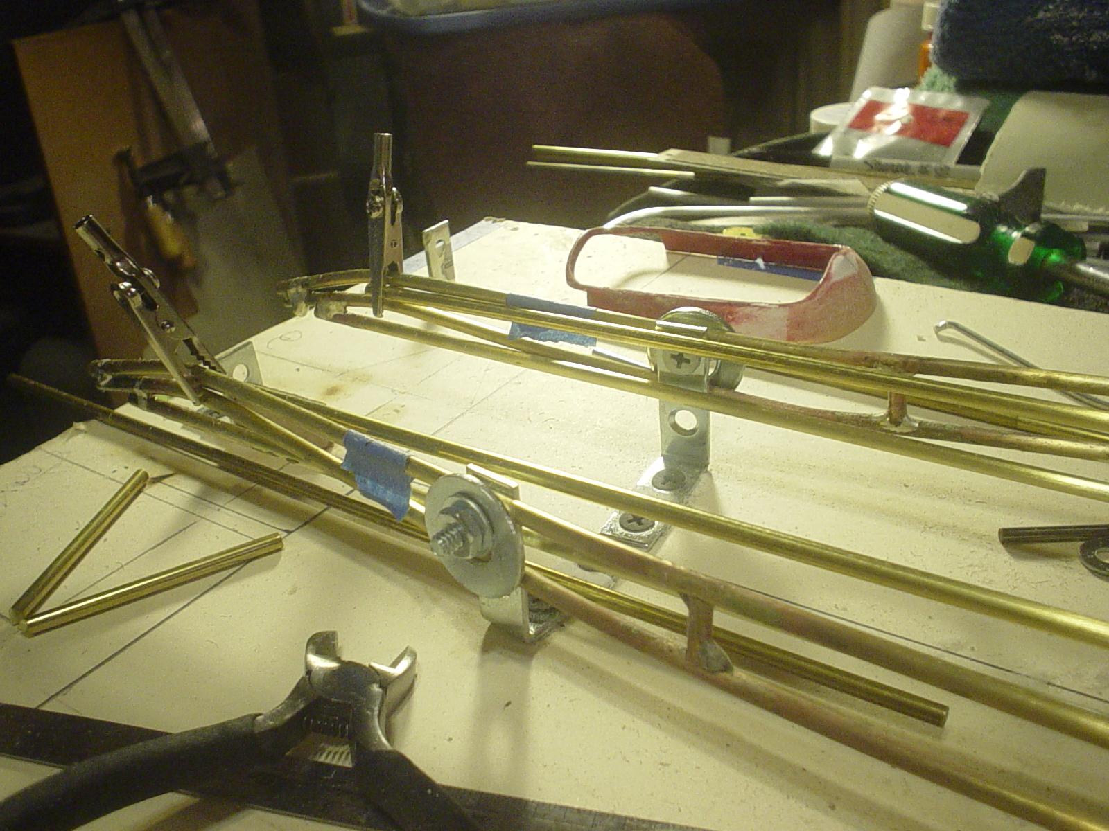
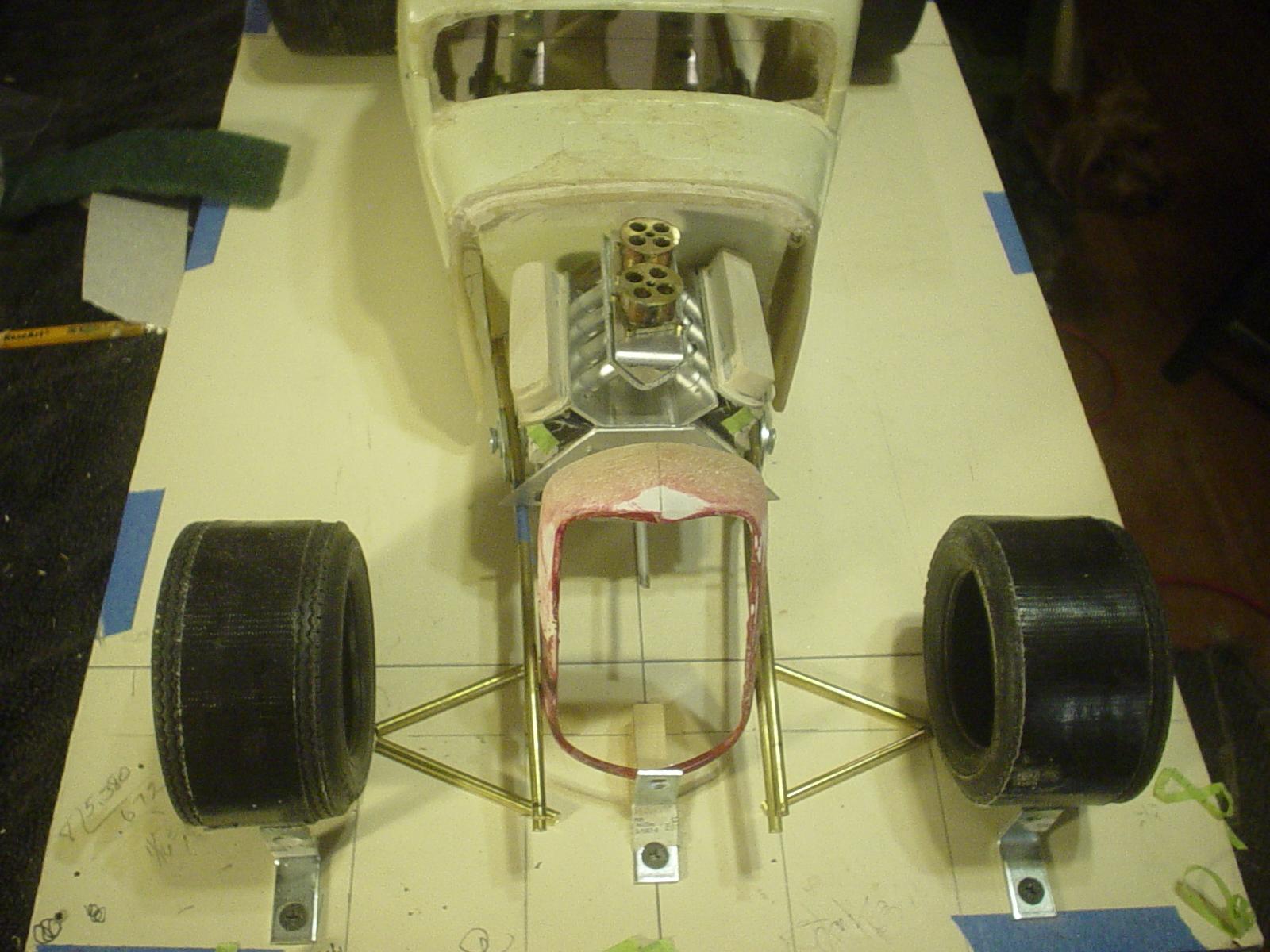
...wondering what if...I were to expose the sides of the frame...& tuck the dump tubes in between the frame tubes....like such... Previous
-
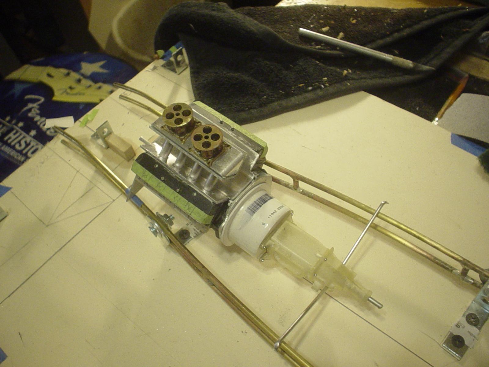
I am having fun building & posting, Tim. All kinds of knotty little "how am I going to do this" problems which are my strongest attraction to this. The nascar motor is a 358" small block...in my head, if this were 1:1, it would be close to 600 ci. Single 4 on this one just isn't radical enough to suit me.
-
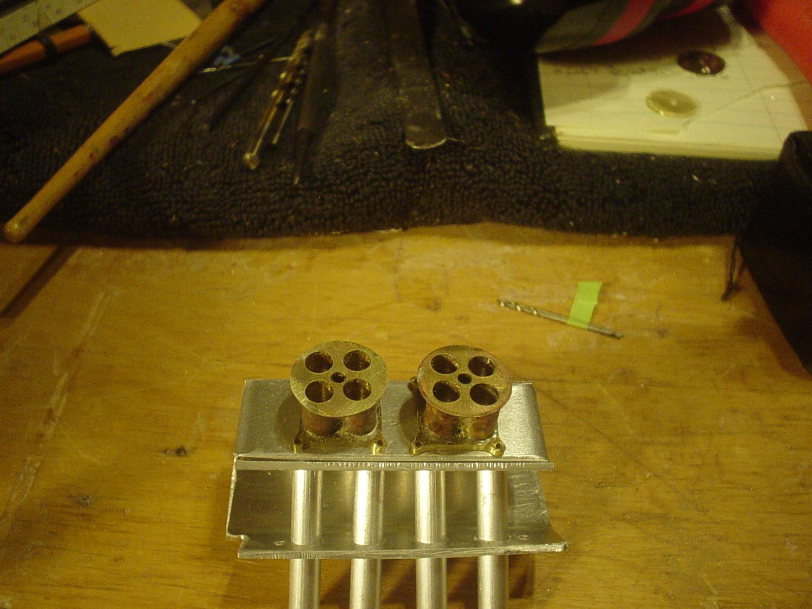
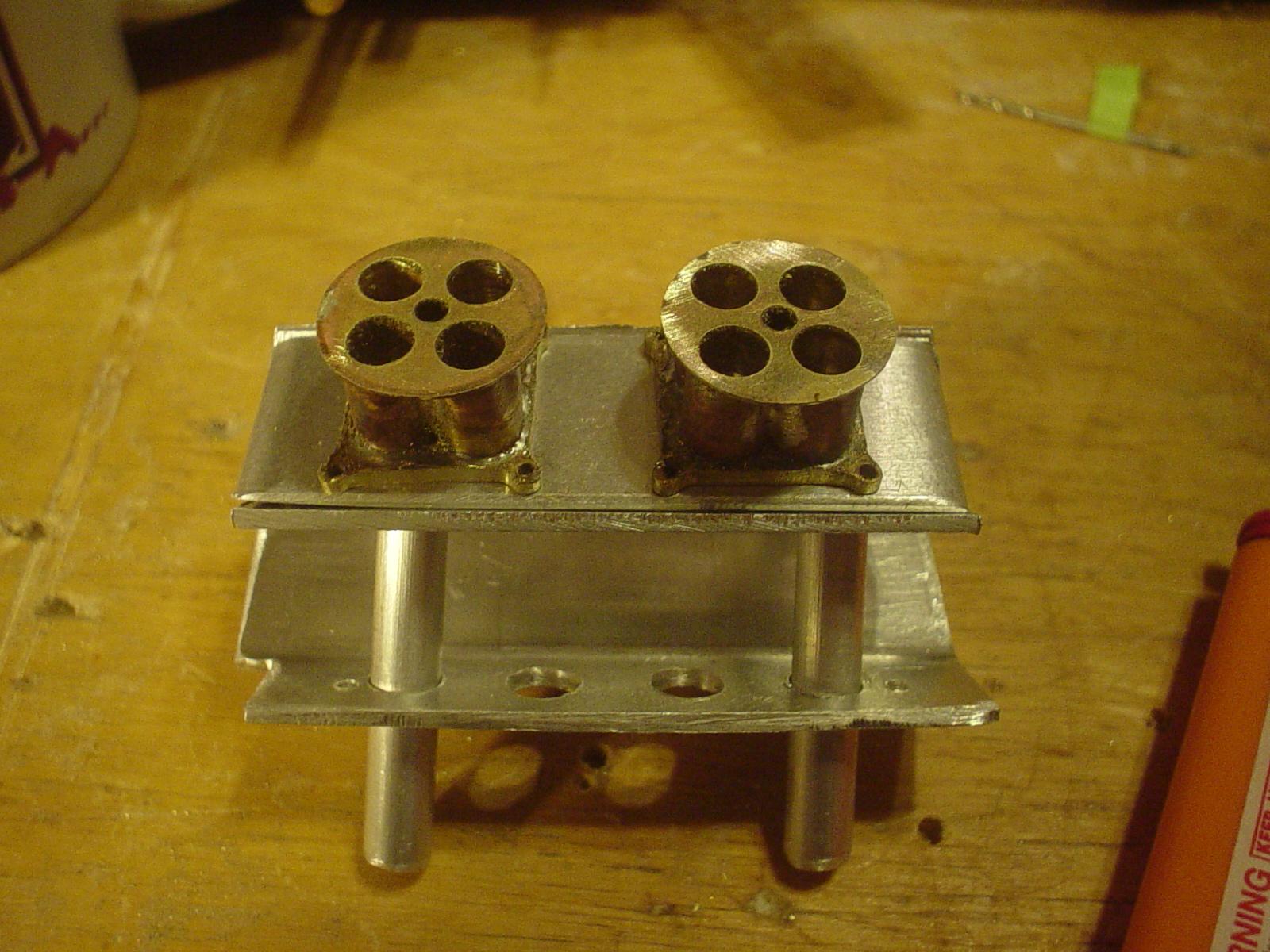
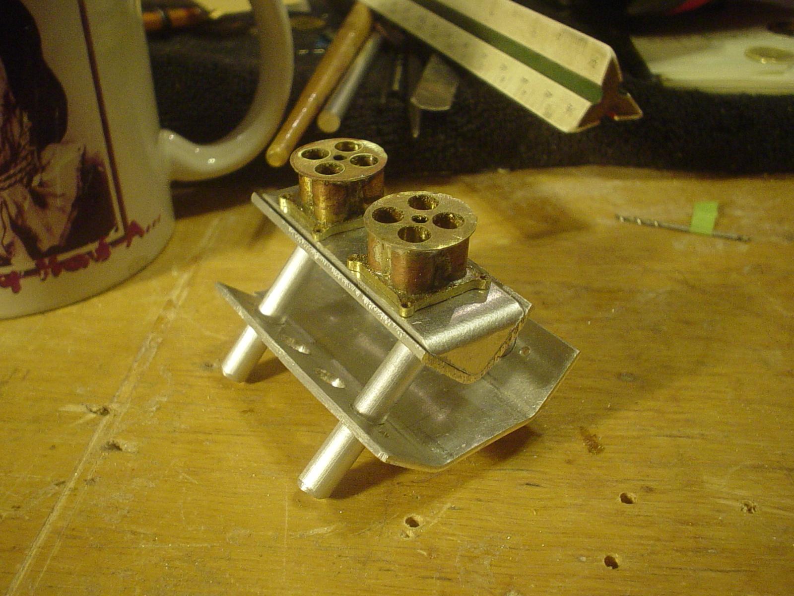
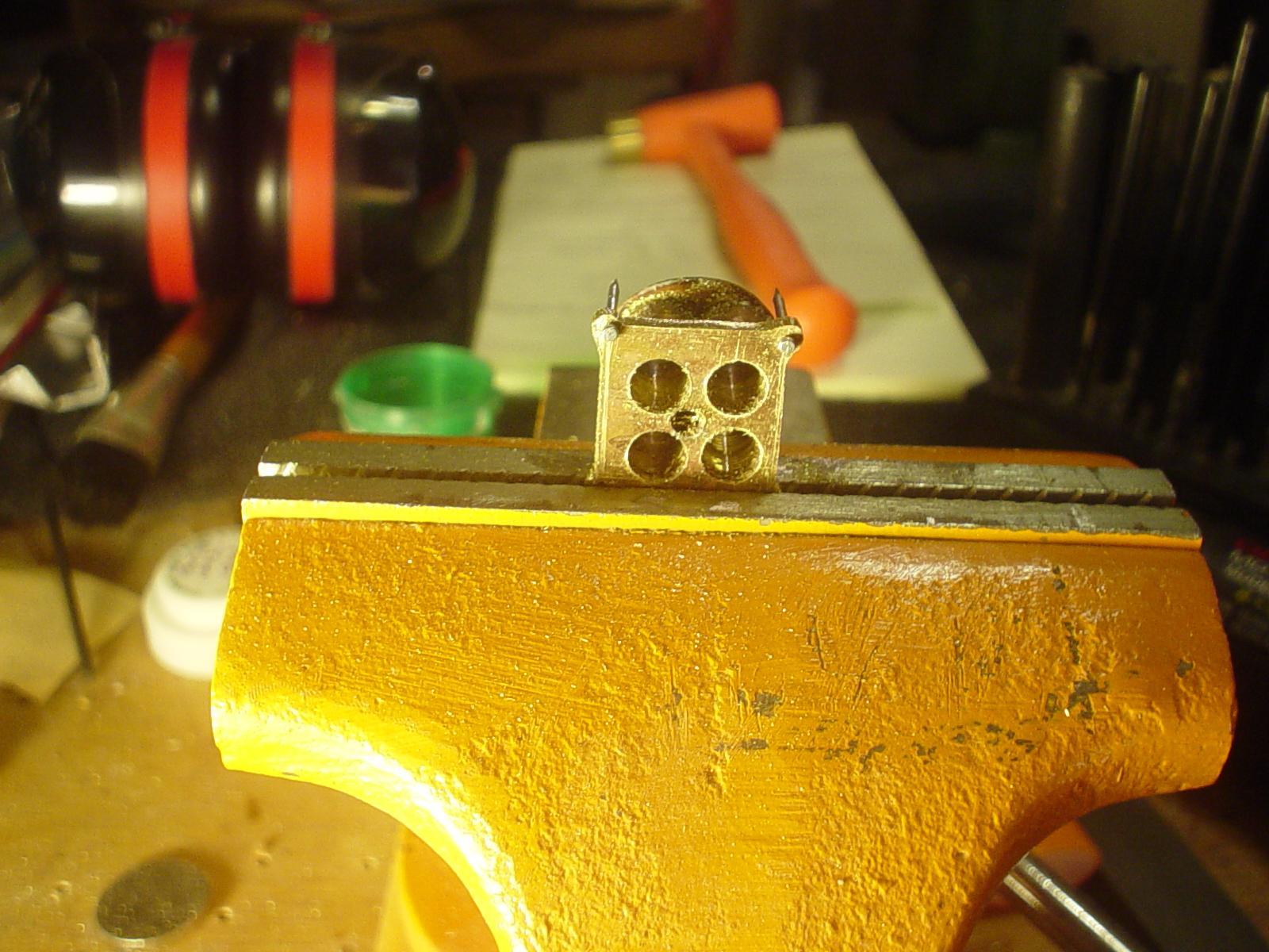
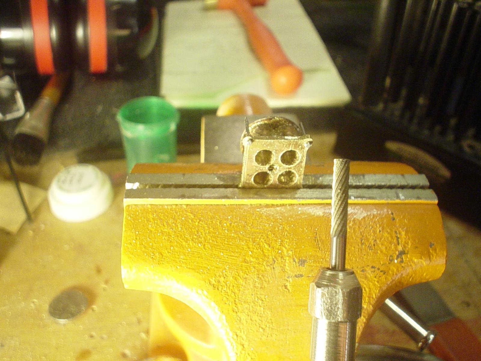
This is the RO7 nascar head. Very business like in it's look. Not trying to do a reproduction here, just grab the vibe & look. Especially want the individual 3 bolt per tube mounting ring feature on my heads. Trimmed most of the excess tube & epoxy off the front. Shaping some aluminum washers to use as retainer rings for the tube to head. With the tube in the head, the header just slips easily in place & hangs securely there with it's own weight.
-
I'll check that out, Michael, thanks. Scott, that's what I'm reading now. I know when I annealed the material when making the aluminum grill shell for the roadster, about half way through, it softened it considerably. Alloy has something to do with it as well, I think & the rod is pretty stiff & hard. Interesting...
-
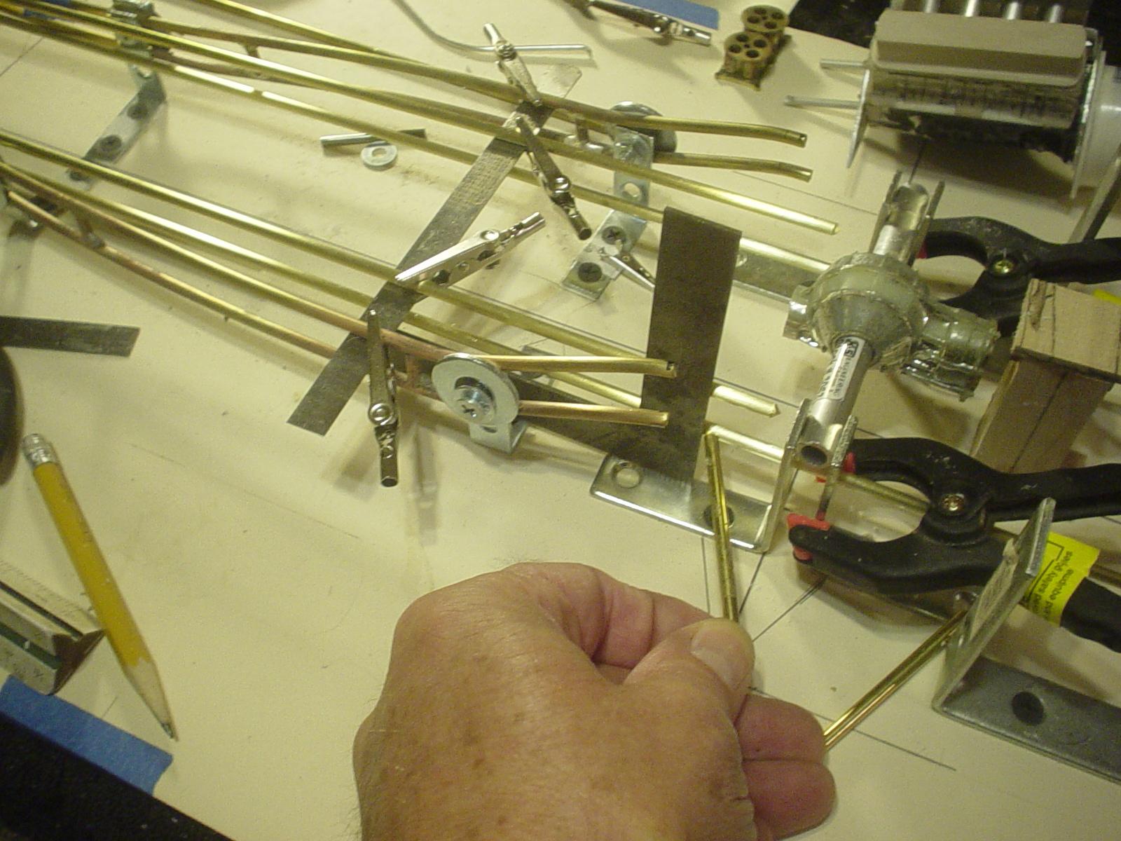
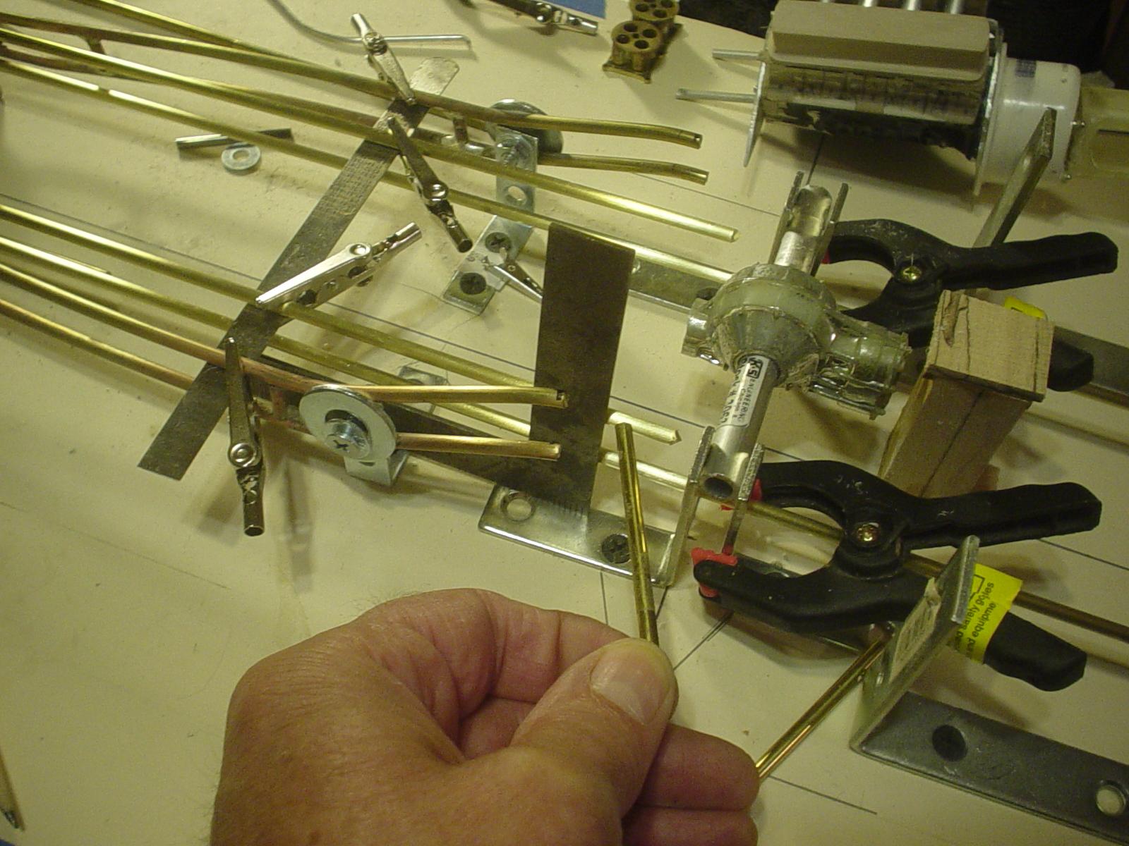
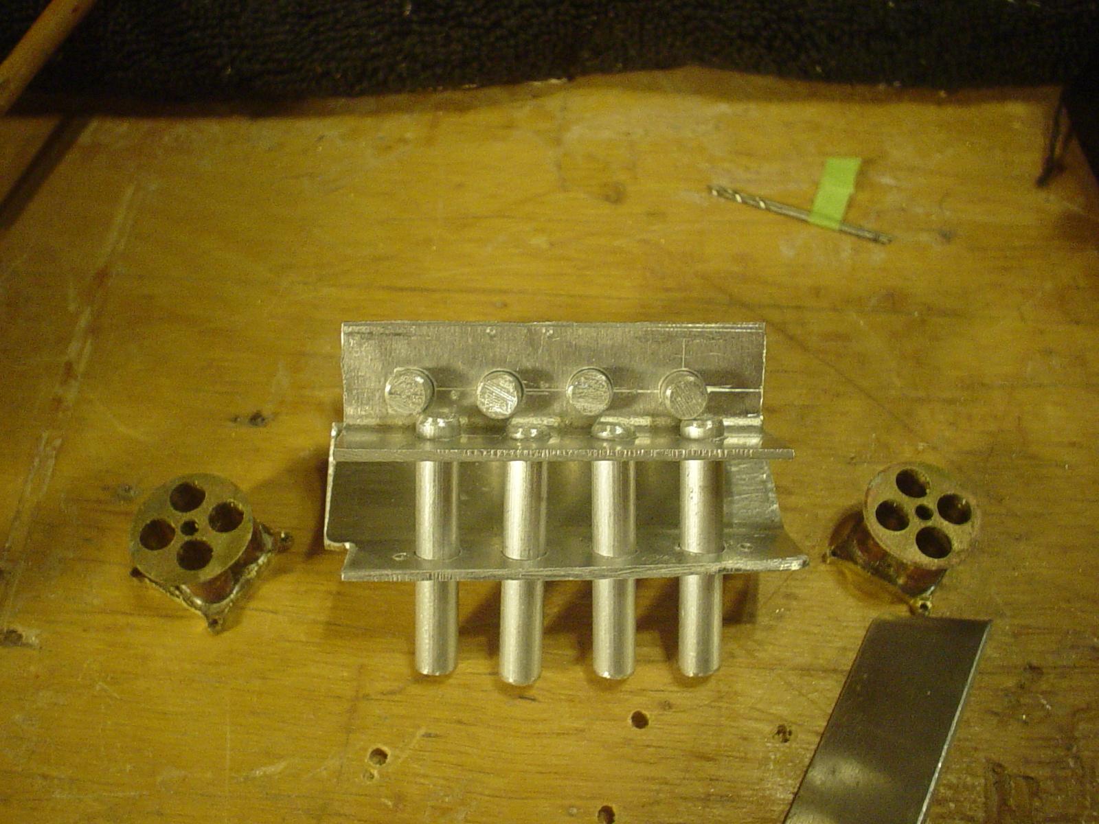
I have a good tight layout on the header jig & accurately executed. Tubing is 9/32...1/4" header pieces slip perfectly into...these tubes will be inserted into the heads & will be mounting points for the headers...slip em on...slip em off. By building the exhaust ports for the heads on the header jig, the layouts should be identical...build headers on jig...remove from jig...should slip right into place on side of engine. Drilled the heads oversized for wiggle room when aligning...packed them with epoxy & joined together. Nice & straight & solid. More epoxy on the front side...need to have material for bosses for header flanges & still provide pads for head bolts. Got one tube bent & in place...subsequent 5 attempts have broke on the tight bend at the top. Need to find a softer, more suitable alloy than the extruded rod.
-
Thanks, Michael. Hoping for good visual continuity...see how it turns out.
-

1/8 1980 San Jose Dirt Car
Ognib replied to Old Sprinter's topic in WIP: Other Racing: Road Racing, Land Speed Racers
Hey Ken, always have enjoyed your builds. Exceptional detail & realism. Never could figure out, though, how you build so quickly when i labor over my stuff forever, it seems. best -
Wow, two different sized pics...don't know how that happened.

-
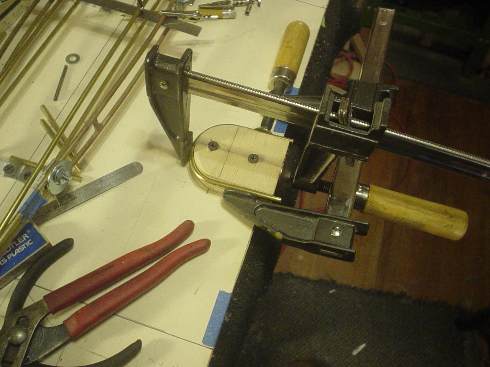
Talk about picking points in space... The blocks that I had the big tube on are ground clearance templates for the header build. They gotta "fit"...fill the space just right!! Square shows me where the front port relates to the platform. Depth gauge for establishing the height of the port relative to.....everything. Build jig with the complete port layout & the angle of the dangle drawn in. See how this goes...
-
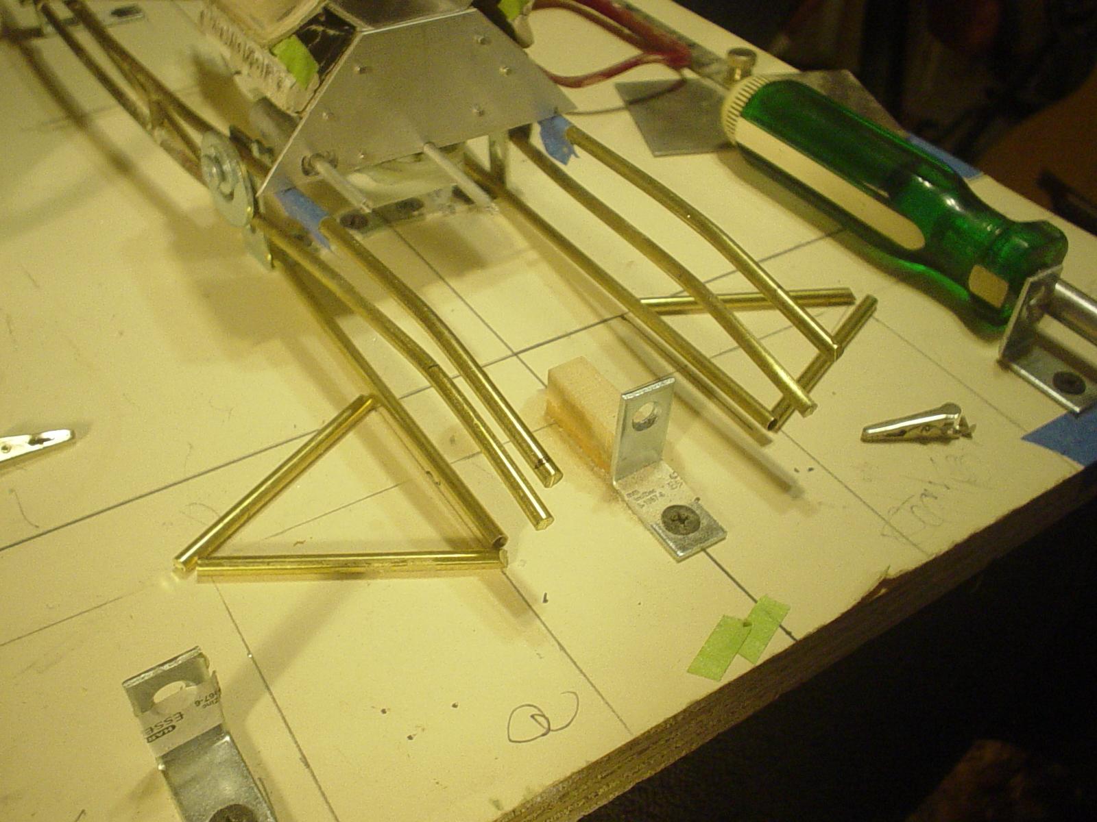
I've got an itch to build a set of headers right now so guess I'll take a break from the frame for a few days. I like the flow of these sprint car headers by husler...will continue the angles established by the laid back grill, cowl side & door line Went & got some more tubing to work with.
-
I only had a short piece of tube to experiment with after trimming off the 2" tail so the bender could grab it. But something kinda like this only longer with the exit back of the rear door line & the primaries feeding in about mid cowl.
-
Thanks Scott...ya it's progressing pretty well at this point. Thanks for stopping in Stephen...appreciate the comments...the jig is worth the initial effort to set it up & it's simple, easy & cheap to build. Takes a bit of time to do the layout etc...gotta double/triple check all your measurements otherwise something won't fit later on.
-
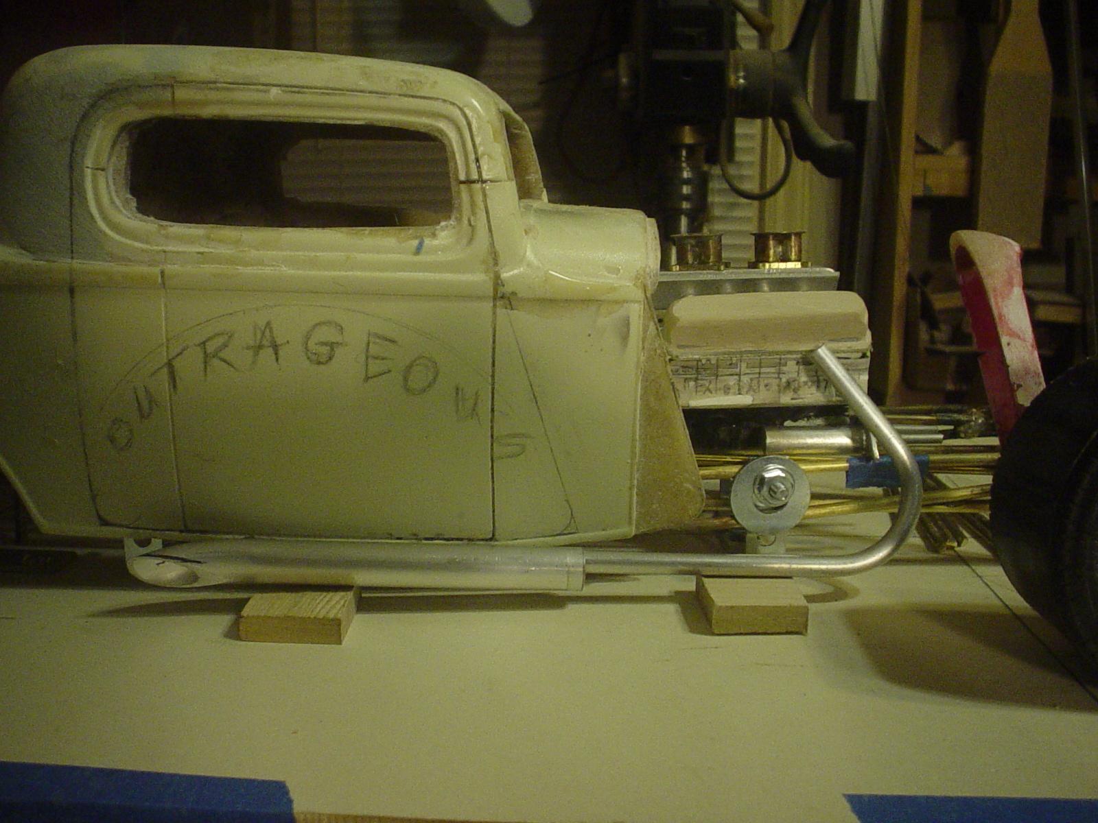
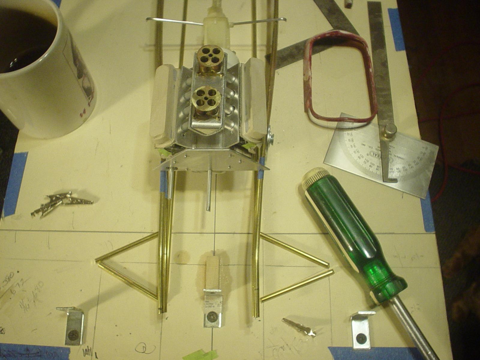
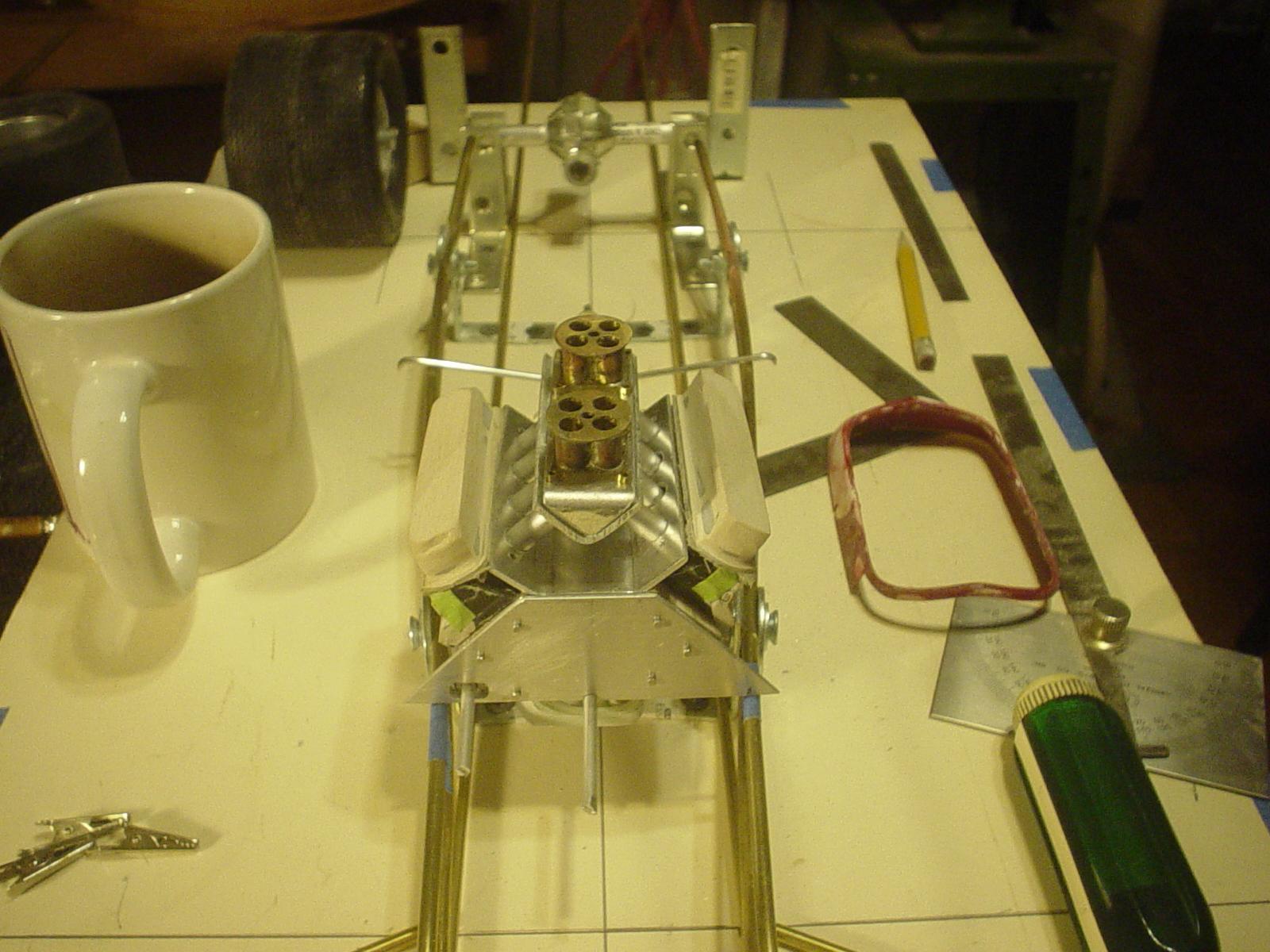
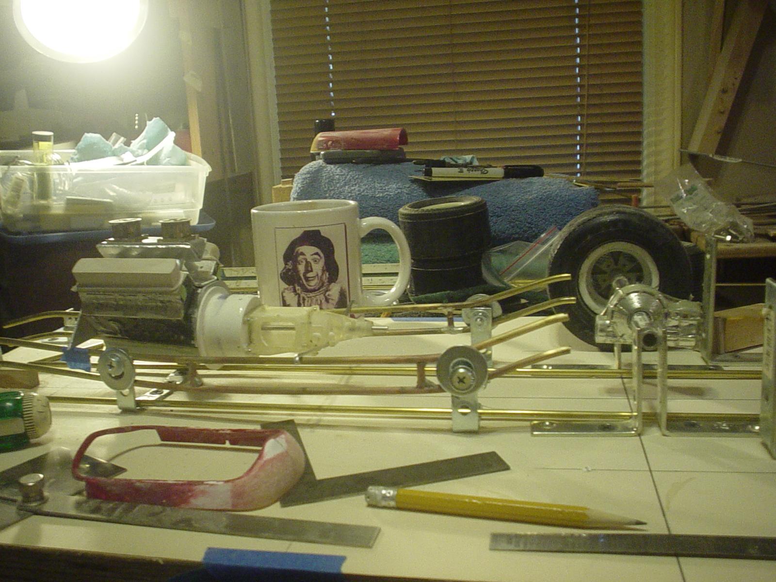
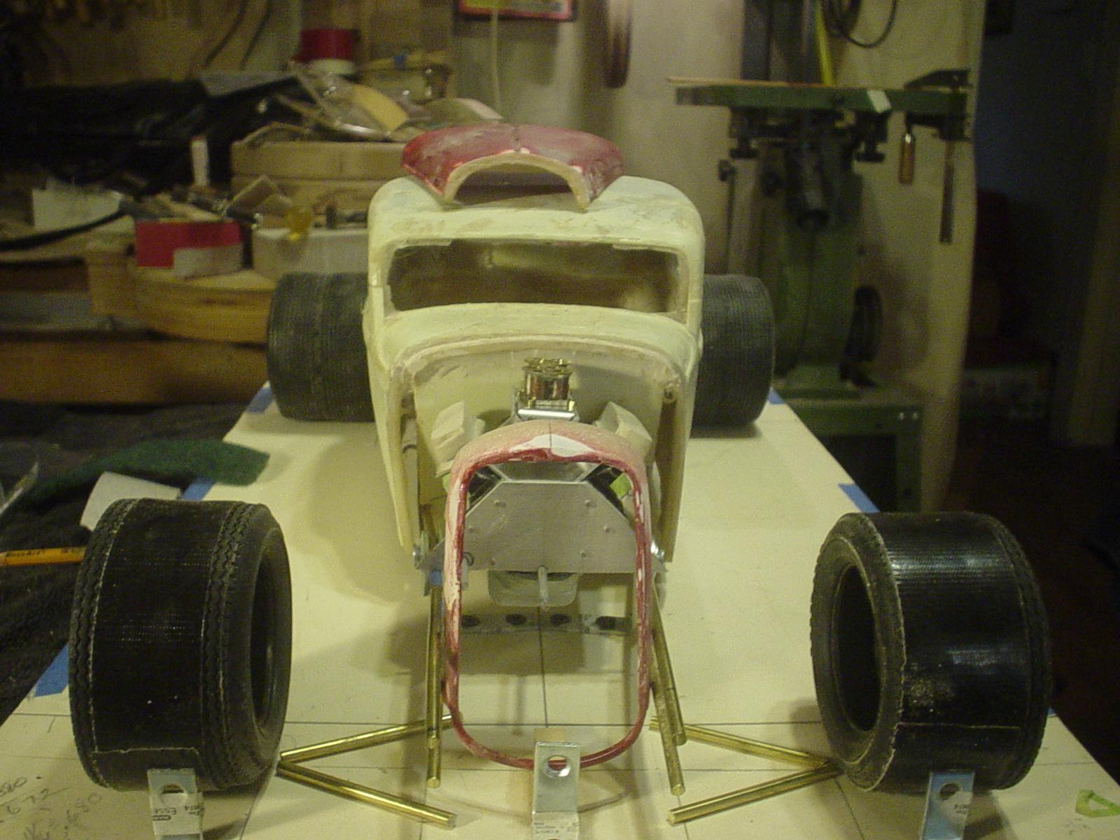
Something the wife picked up for me at a flea mkt...don't hold back dear, tell me how you really feel. Header primary tubes will be .250", 2" @ 1:1...necking down into a .500" dump tube with turn down, 4" @ 1:1. I'm going to set the door hinges before removing the doors to aid in getting a good fit on re-installation. Doors must come out now to give tweezer access to cabin for fitting main hoop & cowl hoop for the cage. I want these in place for fitting struts forward from the center section cradle as I build it. Glad I mocked the dump tube...I'm going to need to raise the lower door line just a bit to open above it.
-
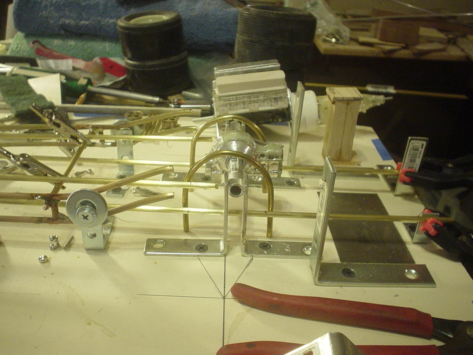
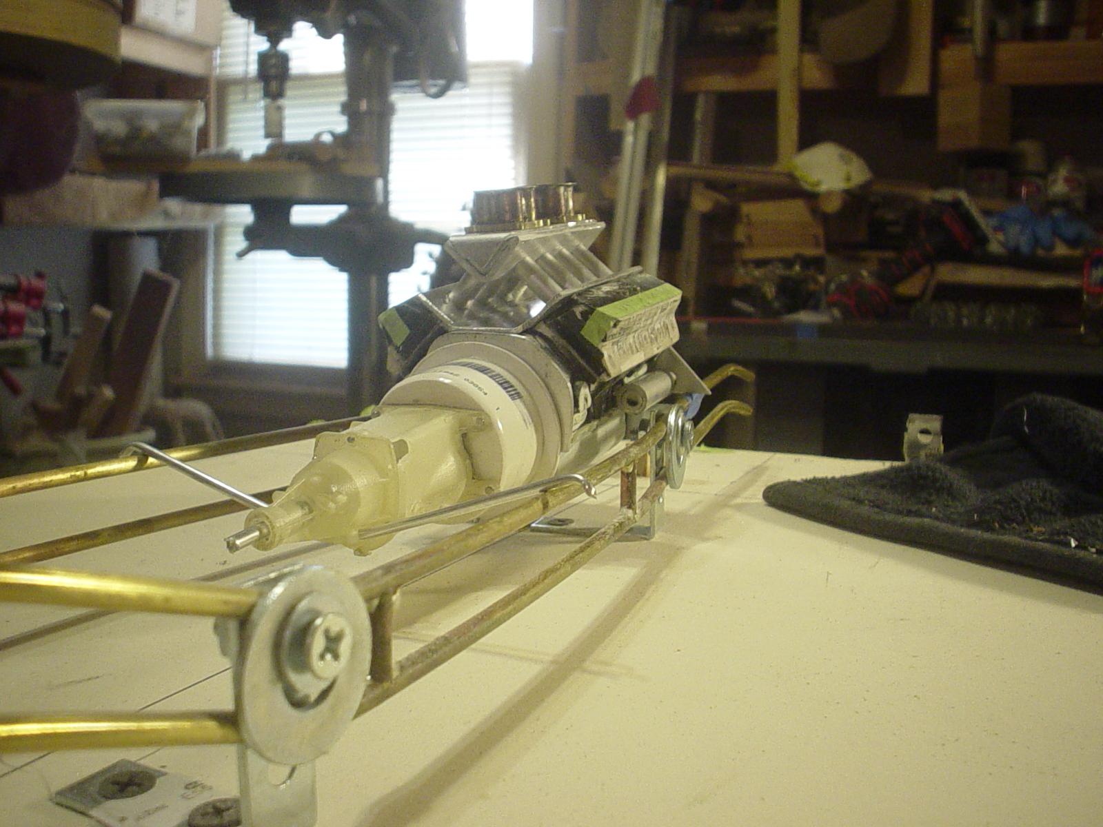
The on going mock up...
-
On going mock ups allow me to constantly visually enjoy the progress of the build as a whole & thus shows me what to do next. The beauty of working in a jig. Everything's locked in position & ya just gotta figure out how link it all together in a clean, logical, straight forward manner. Form follows function. "Pretty" is over rated!
-
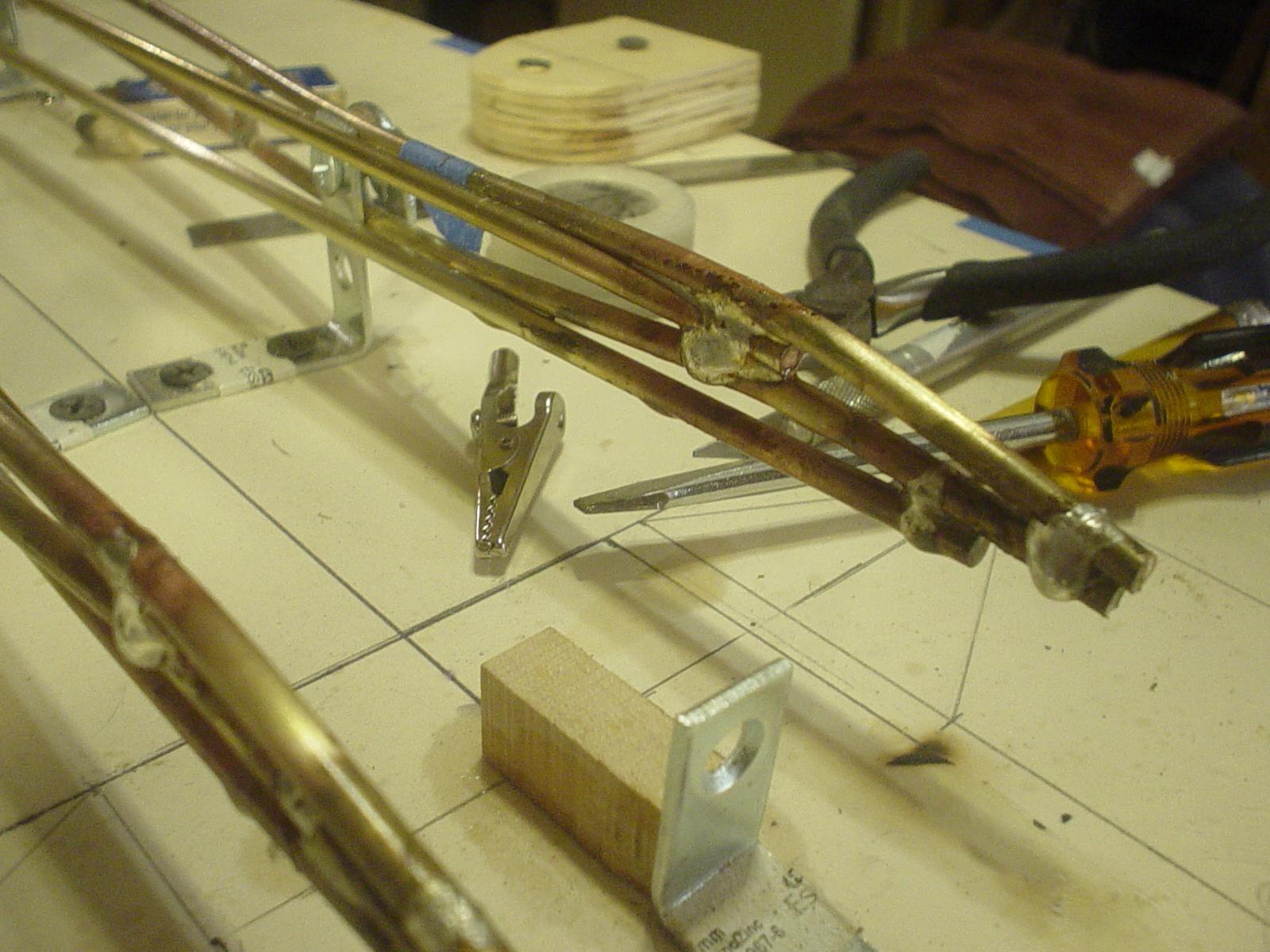
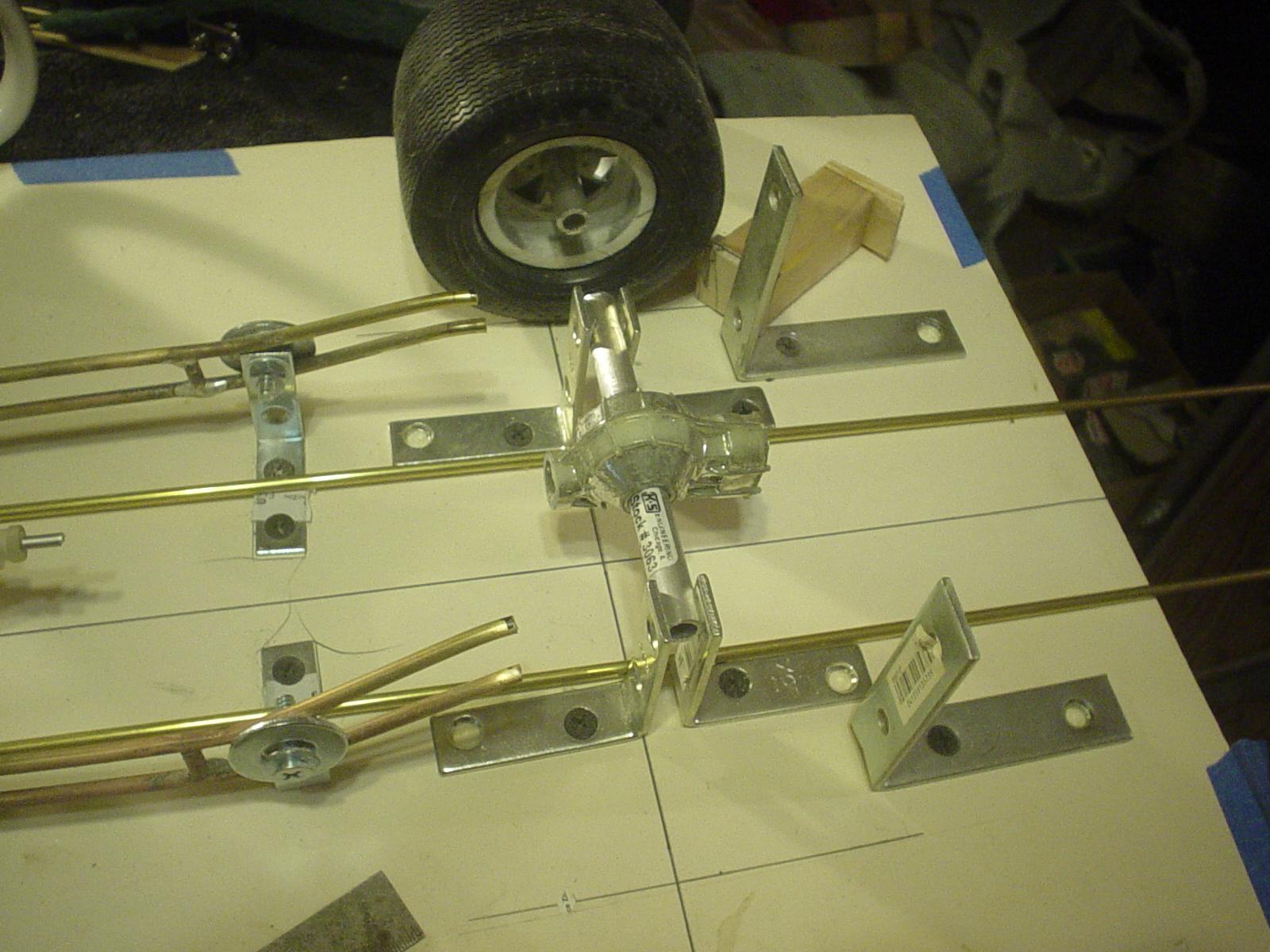
Top inner tube stuck in place. Stuck a temp crossmember in place to hold the upper tube at the correct height.
-
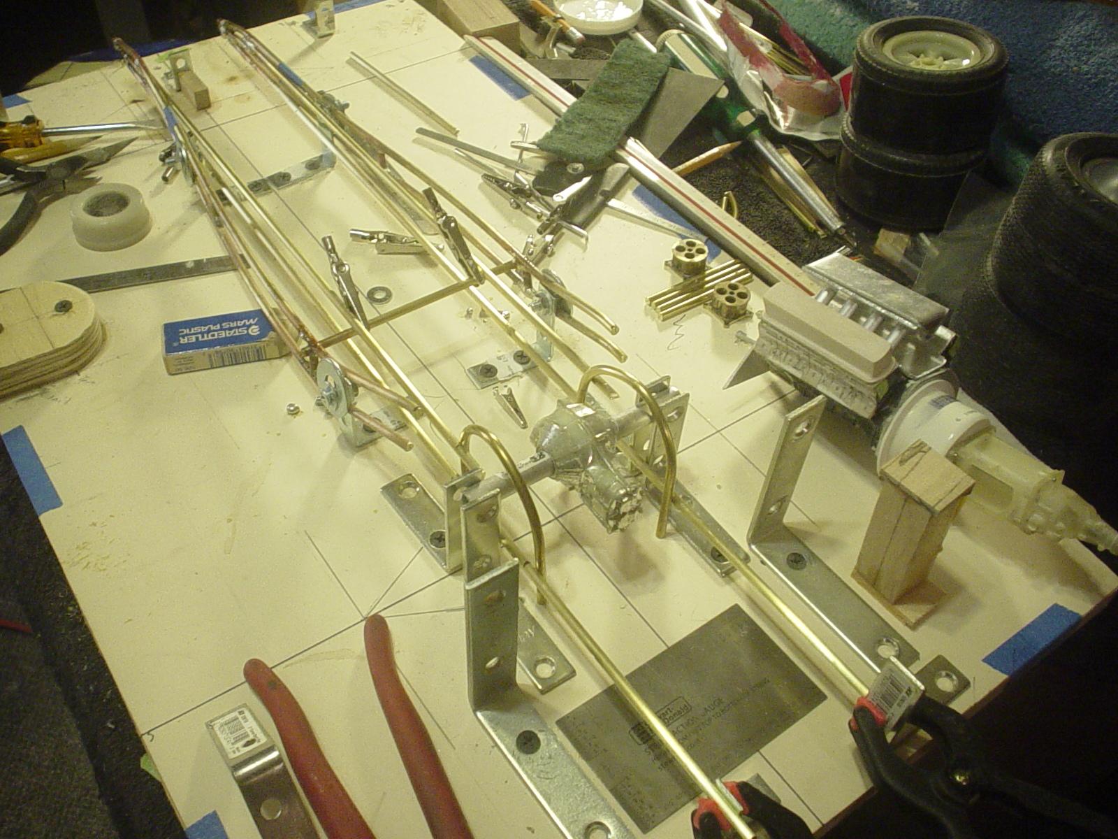
Upper inner rail being fitted. Lower rail will pass under the rear axle shaft & provide mounting points for lower lower control arm as well as the foundation for the center section cradle. Upper rail for upper control arm, looping over the axle shaft in the process. Nice graceful flow of lines where it all comes together in the front.
-
My pleasure, Tim. Thanks for stopping in...always look forward to your comments & insights. The little torch is the cats meow...even with the silver solder & the higher melting temps...it activates the flux & brings temp up to where the solder just flows into the seam...almost instantly...on & off, just that quick. The lead/tin solder is even quicker...used both on building the carburetors.
-
Be happy to do what I can to help. However, you'll need to resend your message...did not arrive on my side.
-
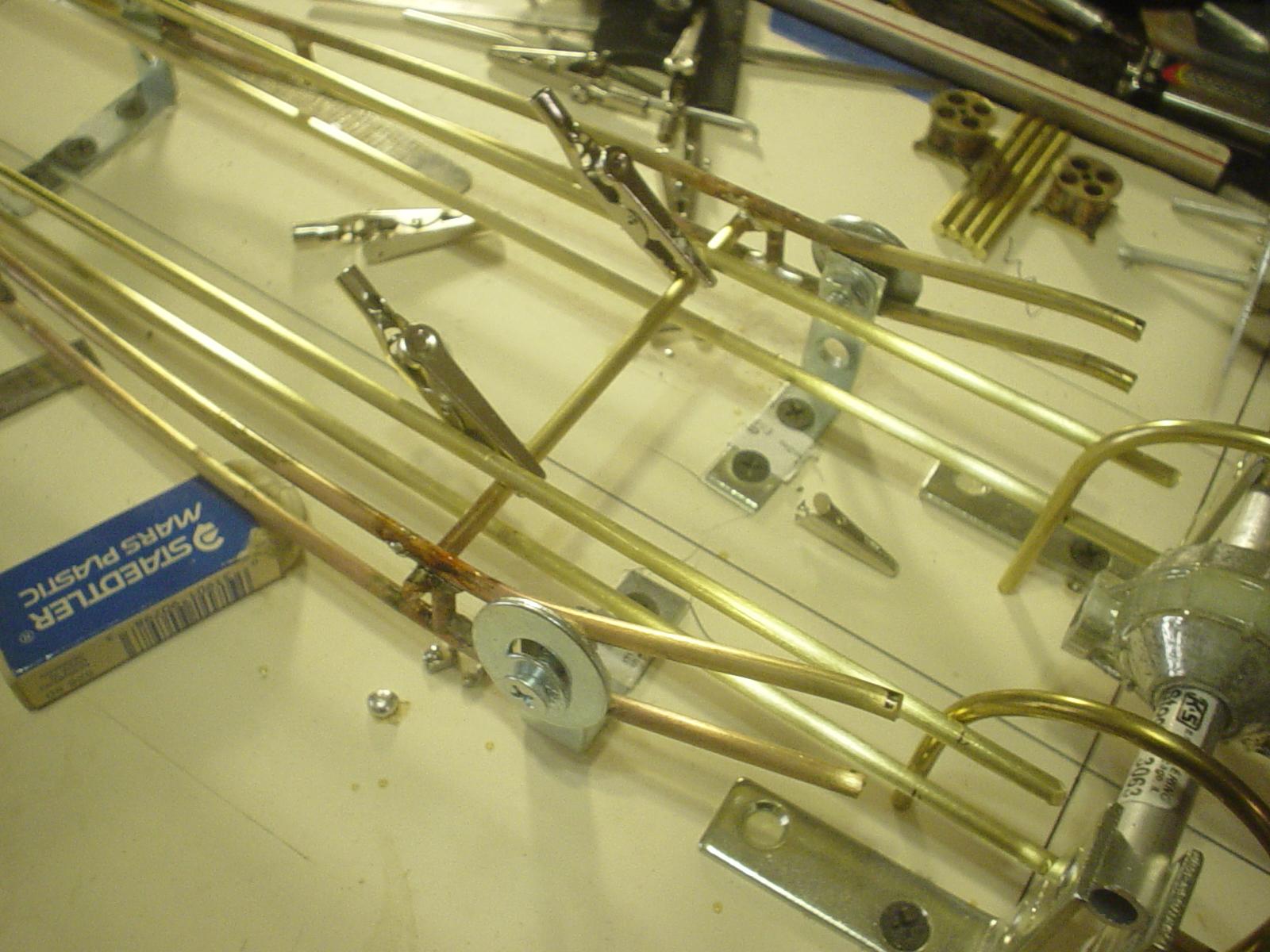
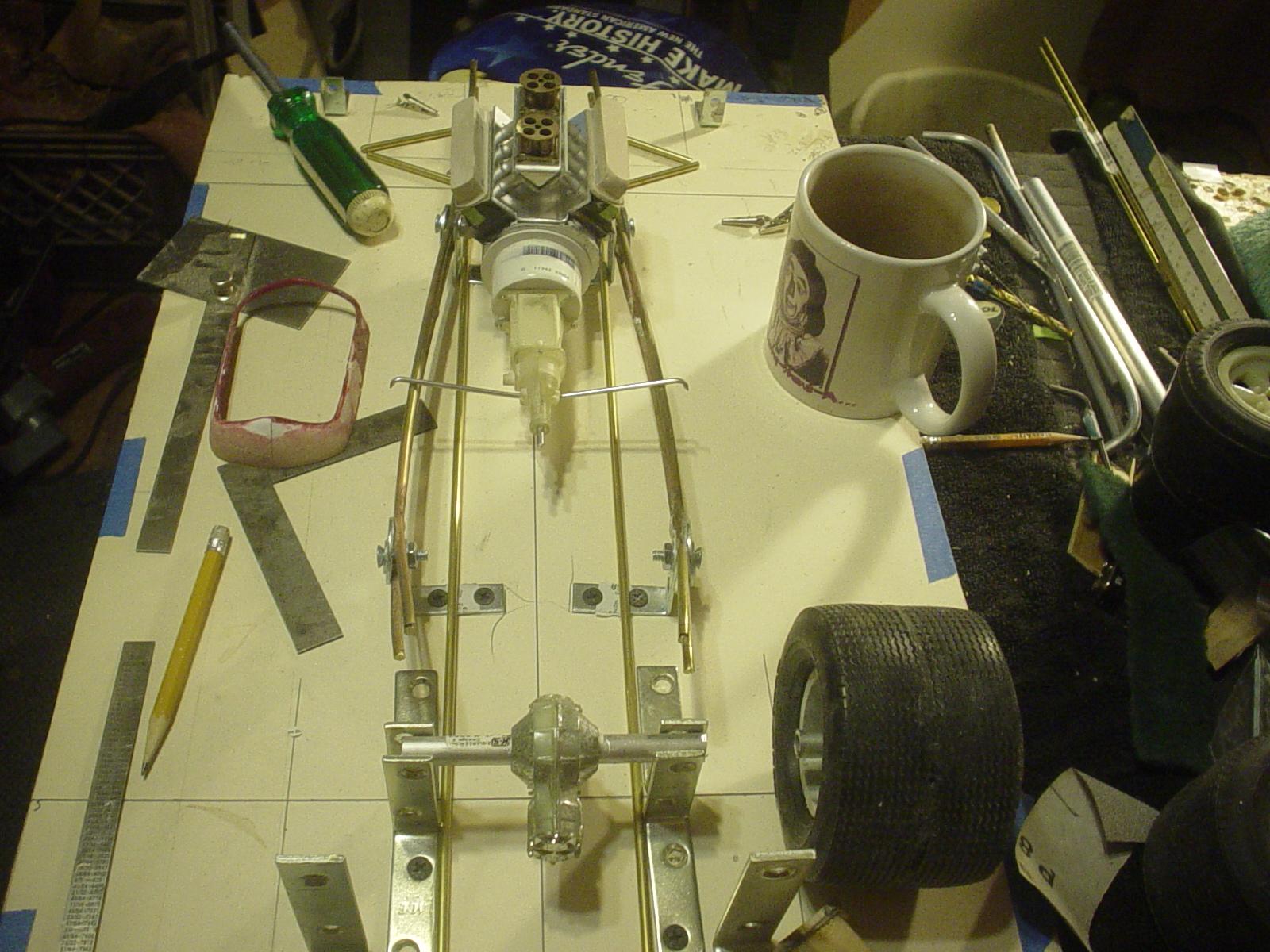
Butane fueled pencil torch & silver solder here. The silver melts at a considerablly higher temp than lead/tin solders...thus I can add things later with the lead without undoing previous work. Temp crossmember holds everything at the proper height. Inner rails run completely parallel to the centerline all the way back. Uprights that hold the center section have been relocated slightly & now also act as side to side locator devices for the tubes. By doing the inner rails this way, there is some visual interruption of the flow of the shaped rails, but form follows function & this is the structurally correct way to do it.
-
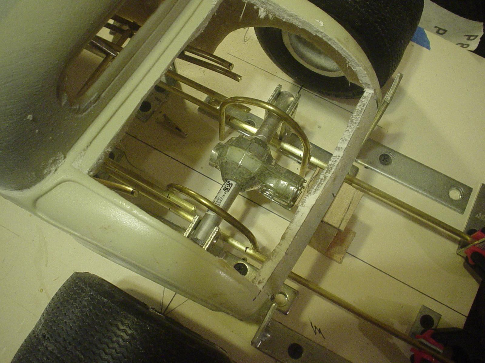
Thanks for the comments guys & thanks for taking a look. Yes...strictly business...form follows function...pretty is over rated! Bob, happy to share the procedure. I enjoy the writing & photography. Eyeball engineering in motion. I've done some reading on the engineering theory of tube frames/cages in preparation for this. Straight lines are the strongest...curved tubing compromises structural integrity. Inner rails, being laid out now, will actually be the main frame of the car...tying the control arm mounts solidly into the structure. The stiffer the frame, the more tuneable the suspension...think autocross corners...or nascar road racing...hard turns in BOTH directions. The curved outer rails are homage to the beautifully classic design of the 32 frame. Included in the design & construction of the front end, along with the control arm mounts, will be placement & mounting points for a steering rack which will need to be built & fitted at that time. The car has IRS as well...thus, the center section does not move...so, the rear cage area needs to incorporate adequate mounting points for this as well as caliper mounts for inboard brakes, a LARGE fuel cell,..it is, after all, a street driver with a big thirsty motor... battery & oil tank for the engine dry sump system. Let's see, am I thinking of everything here?? Ah, yes, I didn't remember to mention mounting points for rear control arms. I really enjoy the design & engineering part of building. I can loose a half a day sometimes just...thinking it through & visualizing the construction. It's like auto cad in my brain! I can see the pictures & video.
-
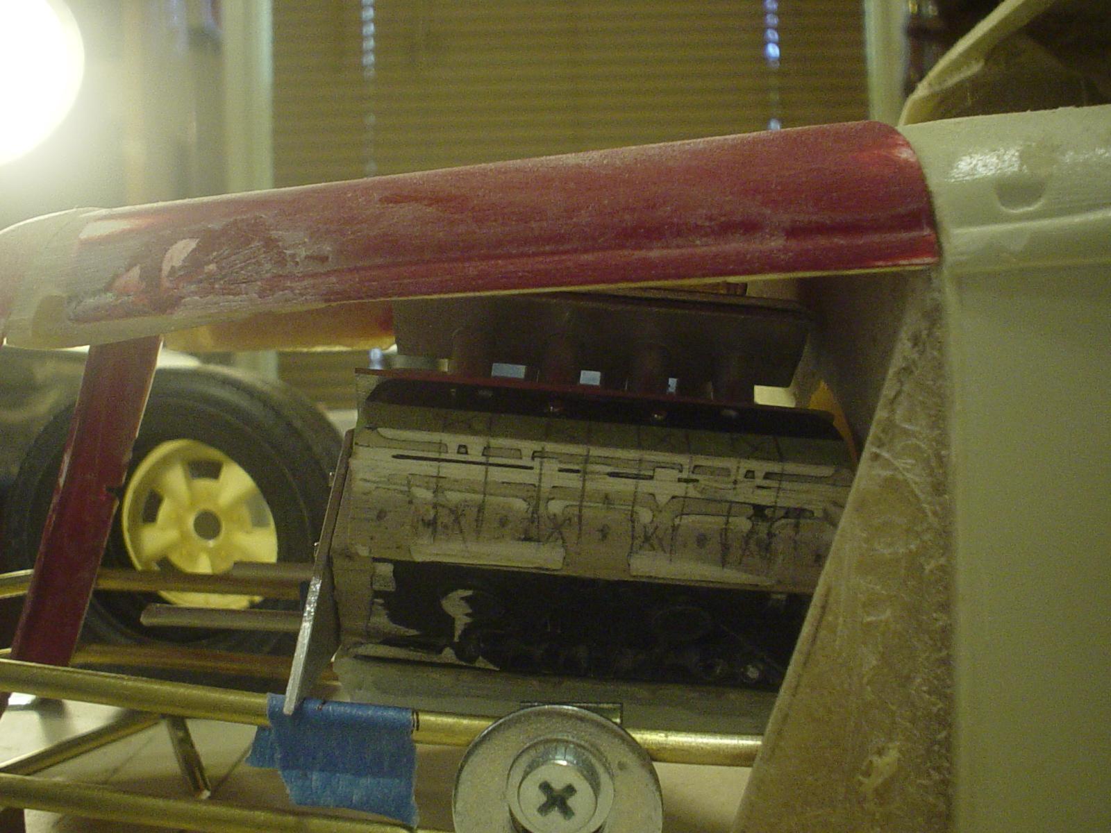
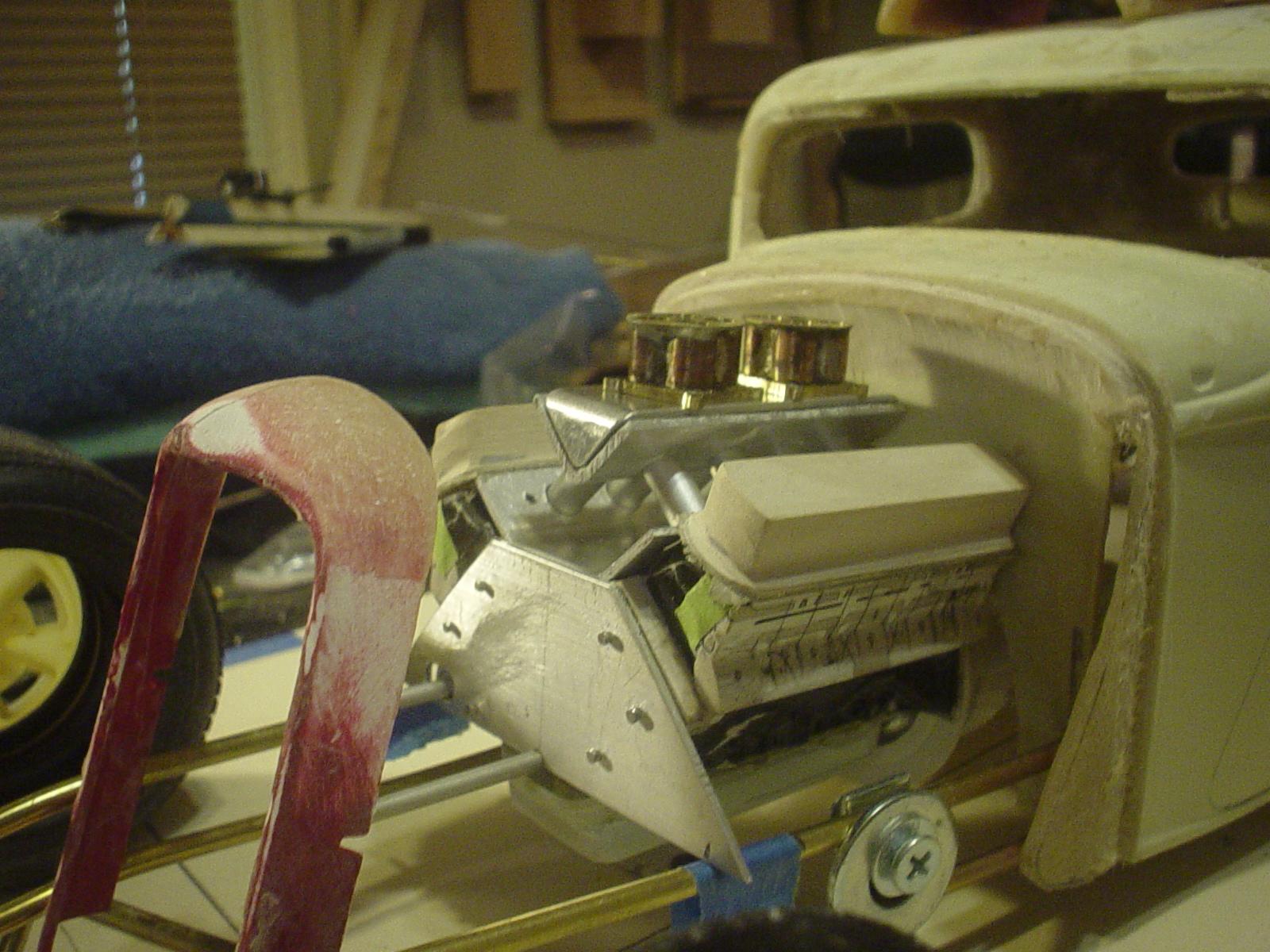
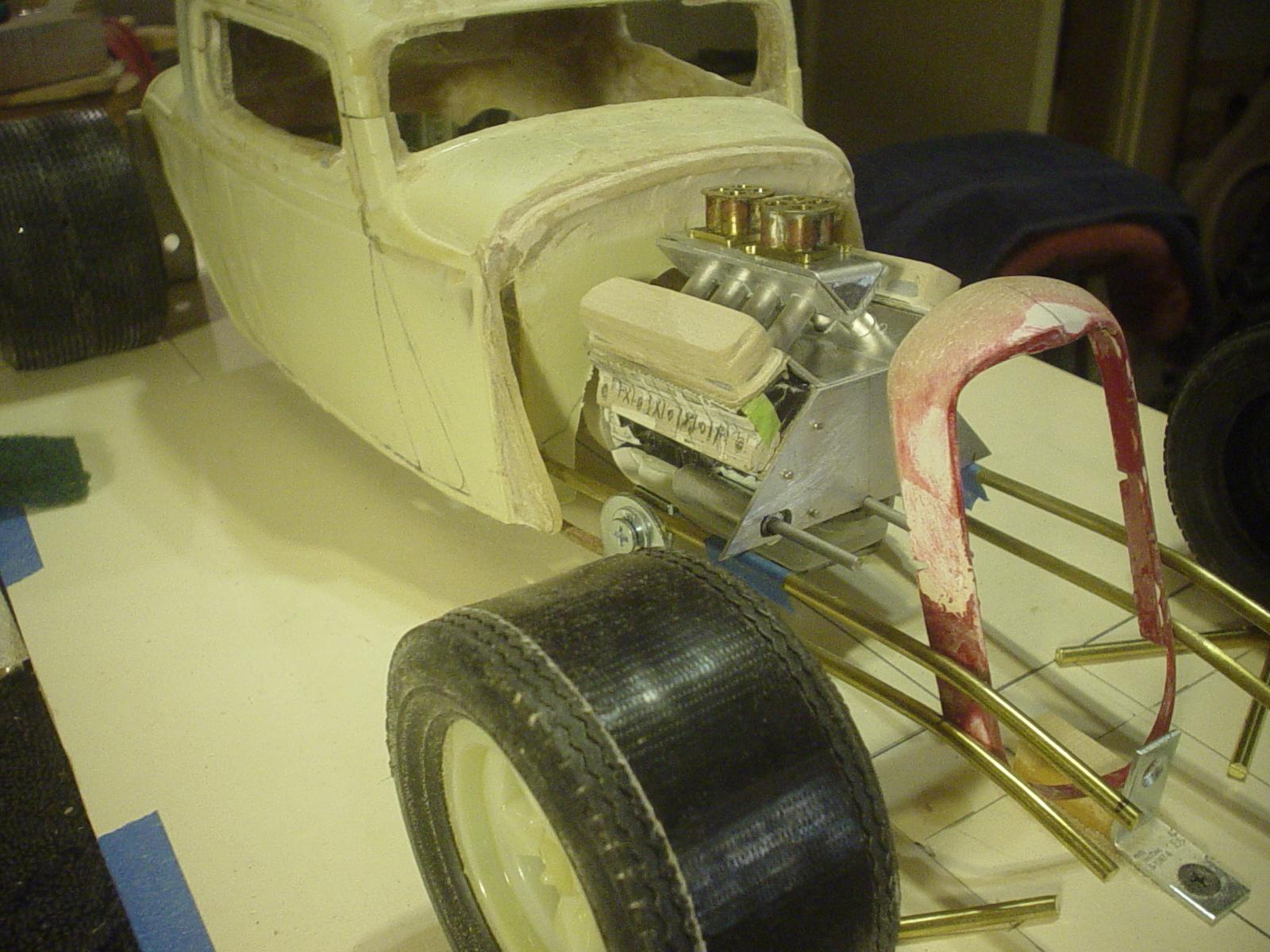
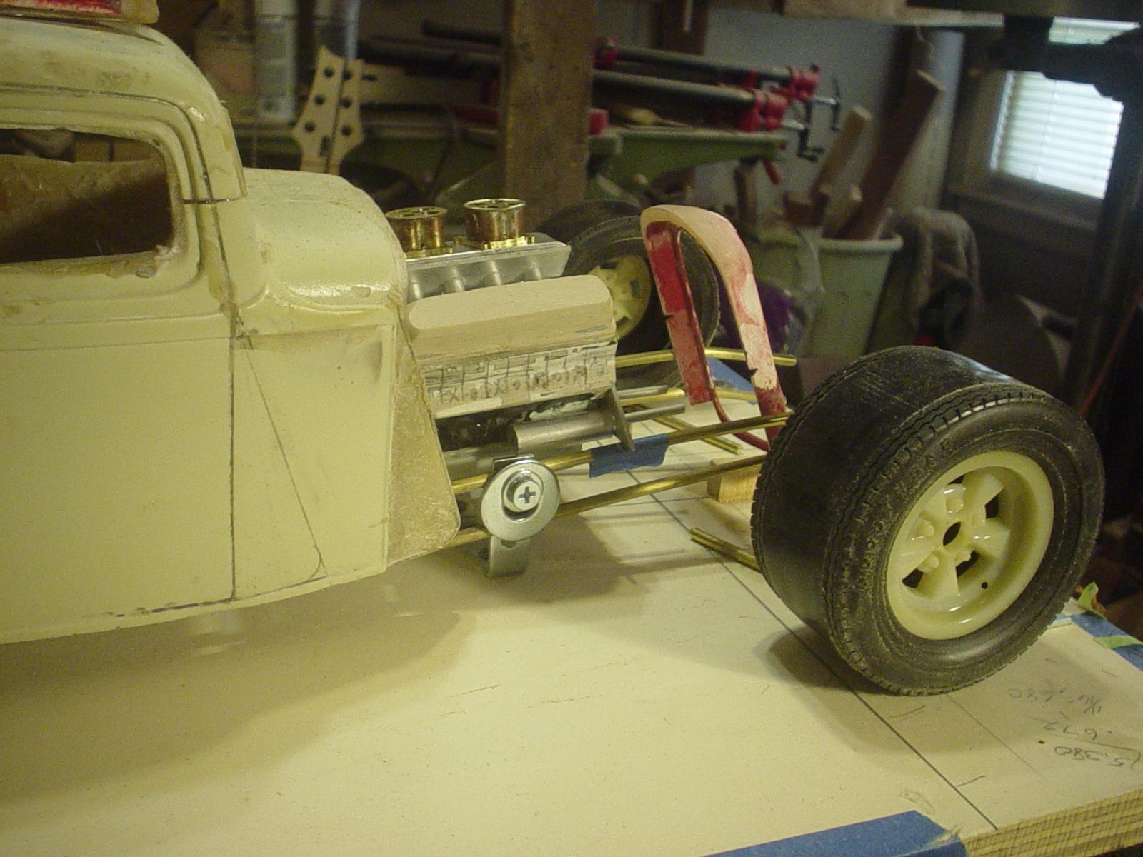
Ya! That's what I'm talking about. Hood fits. Zero clearance, but it fits. Bring the engine down in the frame just a bit. & it'll be good. Liking the way this looks.
-
A tricky part to assemble & get it balanced & properly aligned...10 pieces I like the way it's looking...excited to see it on the motor & in the frame.
-
-
Scratched a line between the mounting holes but beyond that, it's all just eyeballing it to proper shape & visual balance.