IanB
-
Posts
41 -
Joined
-
Last visited
Content Type
Profiles
Forums
Events
Gallery
Everything posted by IanB
-
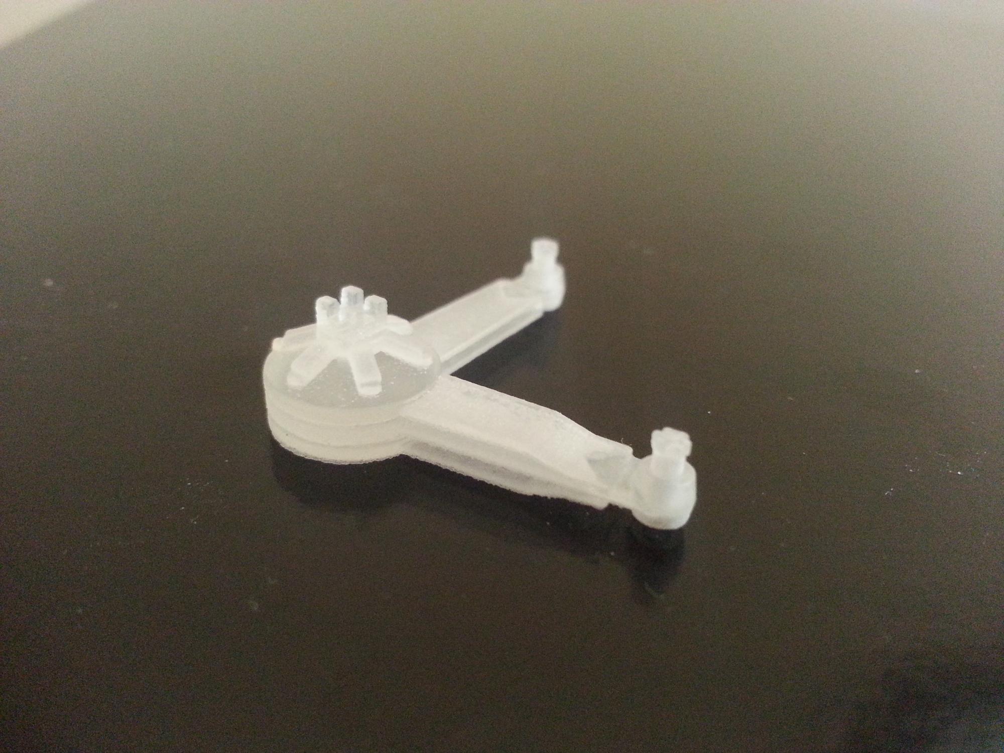
Hi all, Due to the positive feedback I received for my 3d printed friction dampers, I have made them available via Shapeways for anyone who is interested. https://www.shapeways.com/shops/ibdetails They are available as a set of 6, and as a single unit in case anyone breaks one and needs an extra! They are not "handed", instead the mounting nuts and friction adjuster are mounted on pedestals and should be removed with a razor saw, then reattached after the shocks have been mounted. The mounts are not included: either modify the kit ones with .040" (1mm) rod or scratch new ones, the mounting holes are integral to the part. I searched all over for aftermarket parts for this old kit and couldn't find any, so hopefully these will help people out! I hope you like them! Ian

-
The shocks are now available on Shapeways as a 6 piece set, and there is also a one-off available if someone needs a replacement after breaking one... https://www.shapeways.com/shops/ibdetails I hope you like them! Ian
-
Hi folks, I haven't forgotten about this, I just have other builds that are priorities at the moment. Having said that, I got bored with rigging the Short so decided to tackle a little project on this one as a break. Airfix moulded the radiator badge too low so I needed to find a way to put that right. I tried making a mould of it a few months back and destroyed the badge, so I ordered a new rad shell from Airfix. After trying to mould it again I decided it wasn't going to work: I couldn't get the detail fine enough, or make it thin enough. I therefore bit the bullet and decided to graft it! I first removed the badge from the replacement shell, then marked out where it should go and drilled out the centre line. I then slowly and carefully widened the hole until the badge fitted. The top of the shell is a little flatter than the front, so hot water came into play. I made sure I checked it constantly to see if it would bend and in the end I got it sufficiently flat to insert it into the hole in the shell. The edges of the joints at the rear were filled with Mr Dissolved Putty to fill any gaps and give it a little more strength, and when it's dry I'll fill and smooth off the joins at the front..... Ian
-
These arrived in the mail today.... I'm well chuffed! Translated: Very happy with how they've turned out. There's no way I could have got this level of detail by any other means. Now I need to reprint the decals..... Ian
-
I received the prototype this week and I'm very pleased with it! The size and angles look good, so I now need to add the adjusters and mounting bolt heads. I've decided that for ease of printing and to reduce my design workload, instead of making 6 different shocks, (which would be required if I included the mountings) I will leave the mounts off - these can either be scratchbuilt, or removed from the kit shocks and modified as necessary. I will add the bolt heads and adjusters in their correct positions, but raised slightly on a small "pedestal" so that they can be cut off with a small razor saw and fitted on whichever side needs them, thus getting around the left and right handed differences. Doing this means I only need one master and will be able to print 6 identical parts, then easily modify each one to fit where it's needed! Removing the adjusters will be necessary anyway to add the decals for the adjusting plates. I'm looking forward to getting these finished and fitted! 8) Ian
-
Has it really been 3 months since my last progress post? Following another modeller's lead on another forum, I downloaded a trial version of Rhino and have been playing around designing some replacement shocks for this, to be 3d printed. I submitted my order for the prototype today and should have that in a couple of weeks. That will enable me to check the fit and modify it as necessary, then order the full set of 6...... Ian
-
I haven't forgotten this one, just been busy with work, and still waiting for more details on the engine plumbing. Thanks for all the interest! Ian
-
Nearly done with the carb linkages now. The choke mechanism is just resting in place and will be removed for painting before it's installed. I used aluminium tube for the main control rods, with .030 plastic rod drilled out and slipped over it for the brass bushes on the butterflies, these will also be painted tomorrow. The small circular pieces are from a sheet of 1:72 photo etch WWI prop hubs - the perfect size, and the holes are already there! Once the choke is fitted, I'll add the wiring for the mags and fan, the throttle linkage from the pedal, and then the steering column, with the rest of the linkages... Thanks for looking in! Ian
-
I started work on the throttle and advance/retard linkages today. The cross shafts are 0.020" and 0.030" rod, to allow for smaller diameters for the rest of the links. I also made the cooling fan, but can't fit that until I have attached the ends of the oil lines running along the side of the cylinder block - which requires knowing where they go! I'm still not too sure that the fan blades are correct - they just look too long....still thinking about that one... Ian
-
Got the other side of the ignition done, after an afternoon of wrapping tiny wires with strips of masking tape....not too sure about it, but I think it'll do... Ian
-
Here's a little update...work now is fairly slow due to the detail, but each added piece makes a huge difference. I've added all the foot pedals and the brake linkage to the compensator shaft, and started on the engine wiring and plumbing.... I had to remove the part on the compensator shaft that the brake rod attaches to as I made it too short and the rod fouled the chassis. A new part was made and the rod is now straight and clear of the chassis rails. That's it for tonight, I have a 5am start tomorrow. See you all later! Ian
-
Thanks Frank, here you go.... Not much in the way of progress lately as I've been concentrating on the bulkhead details. That is done as far as is needed at the moment, which means the next milestone has been reached - the bulkhead has now been fitted to the chassis. I also spent much of this morning making the clamps for the intake plumbing from the blower.... I'm pleased with how that's turned out, especially as it was one of those "I'll do it later" (ie. how the hell do I do that?) jobs, now thankfully out of the way! I used thin plastic strip wrapped around the trunking, then carved 12 small pieces of 1mm square rod to represent each end of the screw clamp and glued those in place. 0 .4mm aluminium rod was added for the rods, and more resin nuts - I only added the 3 at the front of the clamps, and one under the tie rod. Starting to look like something now! Thanks for looking in, Ian
-
Thanks, much appreciated! I'm putting in as much as I can, no real excuse not to as it's such a large scale. The only problem is getting accurate references.... A little more done - throttle pedal and mounting, and the linkages for the front brakes..... Thanks for looking in.... Ian
-
I now have the pedals finished, with the exception of the actual foot pads at the end, which I will add when the bulkhead is in place. I've also finished the brake compensator. There are still 4 more actuators to make for the handbrake and front brakes, but there's not much more I can do on the brake system until I get the shock absorbers built and fitted, so that will be the next major job (I'm trying to find a good and reasonably priced source for the decals for those). That and making a start on the engine detailing, when I finally receive the hose fittings I ordered in September! I've been told they'll be here soon, so that should be a job for this weekend. Ian
-
A little more progress to post.... I started adding details to the carbs, but I'm not going to go further just yet as I've emailed a museum in the hope of getting pics of their car so I can do them properly. If they don't reply I'll just stick with whatever I make up, at least it will be better than nothing. The dynamo and its bracket and wiring are in place.... along with some of the detail on the front of the bulkhead... I have also added the drivetrain and rear end, adding the shackles I'd made previously, and more resin nuts! I discovered that I've fitted the left rear spring slightly off - it's sloped very slightly inwards, so the differential is centred with reference to the chassis rails, not the springs. This job would have been a lot easier if I'd bought aluminium rod for the shackles instead of using the brass rod I had, and painting it.....lesson learned! Finally, I've made a start on the clutch and brake pedals, and the mounting shaft. Airfix kindly provide the mounting points on the chassis rails, but once again, for no apparent reason, don't actually supply the shaft and pedals - they do provide little plastic blobs that bear no resemblance to the pedals - would it really have been too much effort to have done them properly? I was hoping to make the pedals in one piece but the curve at the top end proved too much. Still, it should make it easier to put it all together if I add the end later. Thanks for looking in! Ian
-
I managed to get the stone screen fitted to the fuel tank today, just need to finish off the straps. Then, since I went to the local modelling club this evening, I put the Bentley together as a dry run..... I'm finally getting close the the stage where I can start to see real progress, and put all the small sub-assemblies together! Ian
-
I plan on thinning the bonnet panels and improving the louvres. The parts were warped in the box. Ian
-
No luck with the bonnet panels, new ones on order from Airfix. A little more to add but nothing major. I've been cleaning up the fuel tank and bulkhead for final painting, and in between I've got some details done. The radiator grille has been masked and painted, but I still have to paint the shell. I've also added some detail on the header tank, and made a dynamo. Thanks for looking in. Ian
-
Couldn't get out today even if I'd wanted to, with a blizzard blowing most of the day. I finally got out around 3:30pm to shovel the drive...again! This is getting old! So...modelling all day! Not much to show for it, but I got a fair bit more done. The coolant pipework had a very rudimentary flange moulded onto it, which I decided wouldn't clean up well enough, and the kit part is also missing a drain plug. So I cut it at the joint with the front mount. A piece of 2mm rod , a resin nut for the drain plug, and a cut down propeller flange from an Airfix kit (you know the piece...the circular bit with a hole in that gets glued to the back of the prop shaft so it turns) made the new flange - it fitted perfectly over the 2mm rod! A few more resin nuts and I have a much more presentable coolant pipe. The piece with the modification: and painted and fitted: I started working on the filler caps, separating the handles, and replacing the mechanism part. I'll refit the handles later. I also removed the oil filler and separated the handle. I have no idea if it's correct but at least it looks better than having a handle moulded onto the cap! A couple of nuts were added to the starter motor as attachment points for the power leads, and a bit of a wash applied to tone it all down a little. Finally, I decided to take a look at the bonnet panels with a view to thinning them down. I got a nasty surprise.... Hopefully some hot water and putting weight on them will sort it out.... Ian
-
I was going to (finally) get another coat of paint on the chassis and bulkhead today, (actually I was going to do it yesterday!) but the snowstorm put paid to anything yesterday, and today I noticed another major flaw with the kit - there is a chassis member missing! Actually there could be 2 missing, but the one at the rear, right under the rear of the body, just in front of the fuel tank, is visible, the other isn't. So, out came the plastic stock and the offending member was added... While that was drying, I decided to add the missing part of the gearbox (the shaft holding the gear lever itself) - I messed that up by adding the final piece too soon, so no pic of that just yet! Maybe I'll get some paint on tomorrow..... Ian Since I've hunkered down for our latest blizzard - we're under a blizzard warning on Cape Cod from 7pm Sat night until 7am Sun morning - I've managed to get quite a bit done today! The first task was another coat of green on the chassis, bulkhead and fuel tank. After that I concentrated on the engine. I decided against repainting the waterway covers, instead I bought some Bare Metal Foil. It's extremely thin, and self adhesive. It goes on very easily and shows ALL detail through it so the surface needs to be well prepared. It trims up very easily, just the weight of a scalpel with a new blade is enough, no pressure needs to be applied. I'm very happy with how that looks now. I then added all the dome nuts. These came from RB Motion and are well worth the money - about $60 for as many as I needed here! I managed to knock off and lose one of the spark plugs which is a little annoying. Luckily it's under the exhaust manifold so I'll replace it with piece of plastic rod and it shouldn't be too noticeable. Once all that was done I could start adding some of the rest of the detail parts: magnetos, pressure relief valves (?), oil filler, crankcase vent, flywheel, water pump and starter motor are now fitted. The inlet for the water pump will be added when the radiator is in place so I can get it to fit properly - I can't believe Airfix don't include it in the kit! I'll add the fan (also not in the kit!) when the engine is mounted in the chassis. I'm hoping I will only need a clearcoat now on the paintwork, then I can start getting stuff added to the chassis! Thanks for looking in! Ian
-
Sorry folks, I just realised I've not been keeping this up to date! So here are a couple of recent posts to update you all... I actually managed to correct the hole I'd drilled in the bulkhead by lining it with 3/8 tube and redrilling. The original was close enough that the thickness of the tube was enough to enable me to move it over about 1mm. It is now in the correct place, central on the bulkhead! I also added another hole for the fuel lines, which will be covered by a "metal" plate, and mountings for the fuel tank. I have no idea if these are correct, but it had to be supported by something so I added a flange around its edge, and a strap at the rear which will attach to the scuttle. The radiator also got some attention. The attachment pins for the front were shortened by 2mm to move it back and leave room for a proper wire mesh grille over the front, which has been added, and the bottom edge has been trimmed with one piece of .015" card, cut and trimmed to shape. I think it's a big improvement! Ian
-
I had intended getting the chassis painted today, but I found more things that needed doing....so I filled the mounting holes for the headlamp brackets and narrowed the ones for the brake actuators, then added some bolt heads to the top of the chassis frame, replaced the moulded blobs on the front chassis spacer with resin nuts/pieces of .04x.04mm rod, and modified and fitted the horn brackets (and added more nuts!) NOW, I think I can get some paint on it...... Ian
-
I've finally finished lacing the wheels! All that's needed now is to file down the spoke ends and a quick blow over to touch up the paint. While I'm doing that I'll put some paint on the chassis too... Ian
-
The biggest problem I'm coming up against with working on an unfamiliar subject, in an unfamiliar scale, is planning! I thought I was about ready to start getting some paint on this, but I then realised that I had more work to do on the firewall, steering column, and leaf springs. I added the nuts on the leaf spring shackles, and then decided that I needed a different approach to the firewall so that I didn't have an untreatable joint when I put it all together. I therefore cut the front part of the floor off, and attached it to the firewall, added some stock sheet to cover the joins, and filled and sanded as necessary. Much better! I then decided I wasn't happy with the part I'd added for the throttle bracket mounting, so I removed it and remade it, slightly bigger. I'm now happy with that and have redone the aluminium paintwork. Now I am not happy with the circular blanking plate over the oil tank so I'll repaint that later! The petrol and oil header tanks have been added, as well as a new steering column mounting bracket on the rear of the firewall. The end bolts have been added to the steering column and a little more clean up done on that too. Finally I made up the remaining 140 spokes needed and have prepared them for painting... I'm hoping that by painting the spokes first, all that will be needed when the wheels are complete is a little touch up......we'll see....... Thanks for watching....any pics or details of the fuel and oil lines and where they run would be more than welcome.... Ian
-
Harry, it's the same amount of drilling either way! Whatever you prefer would work. Doing it this way gave me a break - my fingers were going numb, those rims are VERY thick! Plus the holes needed cleaning out after the sanding anyway...the front rims were drilled in one go, they're much thinner. Thanks for following! Ian