

robdebie
-
Posts
386 -
Joined
-
Last visited
Content Type
Profiles
Forums
Events
Gallery
Posts posted by robdebie
-
-
Matt, a huge thanks! I'll start drawing that logo straight away.
Rob
-
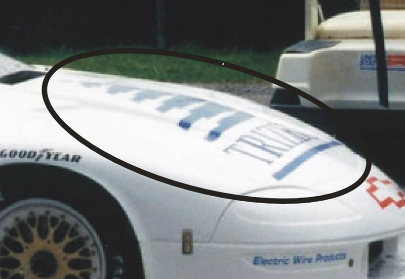
I'm drawing decals for a set of 1995/1996-ish SCCA Trans-Am Camaros. I'm working on the Kenny Wilden #40 car, and it's done except for the large hood decal. I've photoshopped it to make it more visible, and I read 'TRIZE...". Does anyone recognize this sponsor logo? Many thanks in advance!

Rob
-
On 9/18/2022 at 11:24 PM, Rick L said:
That’s exactly what it is. It’s a result of the plastic flowing through the mold from different directions from different injectors. The plastic from one injector is colder than the other and setting up before it meets the plastic from the other injector resulting in a parting line throughout the part that unfortunately will not buff out. Bummer!
To add a bit: that's why the best clear parts are molded form just a single injection point per part. That of course avoids the weld lines. Take a close look at different clear part sprues / runners to see what I mean.
Rob
-
On 9/17/2022 at 12:30 AM, Horrorshow said:
Anyone know where I might get custom decals? Only need numbers in certain fonts, styles and colours for 1/24 and 1/25 NASCAR builds. I don’t have equipment to do it myself.
I do custom decal design from time to time, here's a webpage I made explaining the process:
https://robdebie.home.xs4all.nl/models/customdecals.htm
You could also browse through my lists of custom decal printers, a few also offer artwork drawing services:
https://robdebie.home.xs4all.nl/models/decals.htm#custom
https://robdebie.home.xs4all.nl/models/decals.htm#other
Rob
-
On 9/17/2022 at 11:33 AM, beeRS said:
I'm also wondering if there's a company that will print my own custom made decals for me? I can do artwork on Photoshop, but I don't have a decent printer.
I have two lists of custom printers on my Alps decals webpage: one with custom Alps printers, and one with other printers:
https://robdebie.home.xs4all.nl/models/decals.htm#custom
https://robdebie.home.xs4all.nl/models/decals.htm#other
Having artwork in bitmap (pixels, Photoshop) might be a problem, the majority only prints vector artwork (CorelDraw, Illustrator).
Rob
-
1 hour ago, stitchdup said:
I've got the yamaha and bronco set. If I recall correctly the boat was pretty simple. I can look it out and get pics if you want
Yes please! My interest in these models is growing, I just watched some YouTube movies of races from the eighties. In the open version, the driver/captain/pilot was not strapped in, and often ejected in a crash.. The color schemes are nice, resembling race car color schemes from that era.
Rob
-
In 1990 and 1991, Revell USA and Revell Germany issued three car kits that included a Formula 1 speedboat and a trailer:
- Revell USA 1/25 Mach I Formula One Team, catalog number 7240, 1990 (see https://www.scalemates.com/kits/revell-7240-mach-i-formula-one-team--499727)
- Revell USA 1/25 Yamaha Formula One Team, catalog number 7241, 1990 (see https://www.scalemates.com/kits/revell-7241-yamaha-formula-one-team--947549)
- Revell Germany 1/25 F1 Racing Boat & Trailer & Ford Bronco, catalog number 5236, 1991 (see https://www.scalemates.com/nl/kits/revell-5236-f-1-racing-boat-and-trailer-and-ford-bronco--144150)
Does anyone know more about the Formula 1 speedboats in these kits? Do they represent a specific design? The second kit has an enclosed cockpit, but are they identical otherwise?
I remember seeing the Formula 1 speedboat races on TV back in eighties, and I might want to build one, one day. But right now I know hardly anything about the subject.
Thanks in advance!
Rob
-
23 hours ago, Mike C. said:
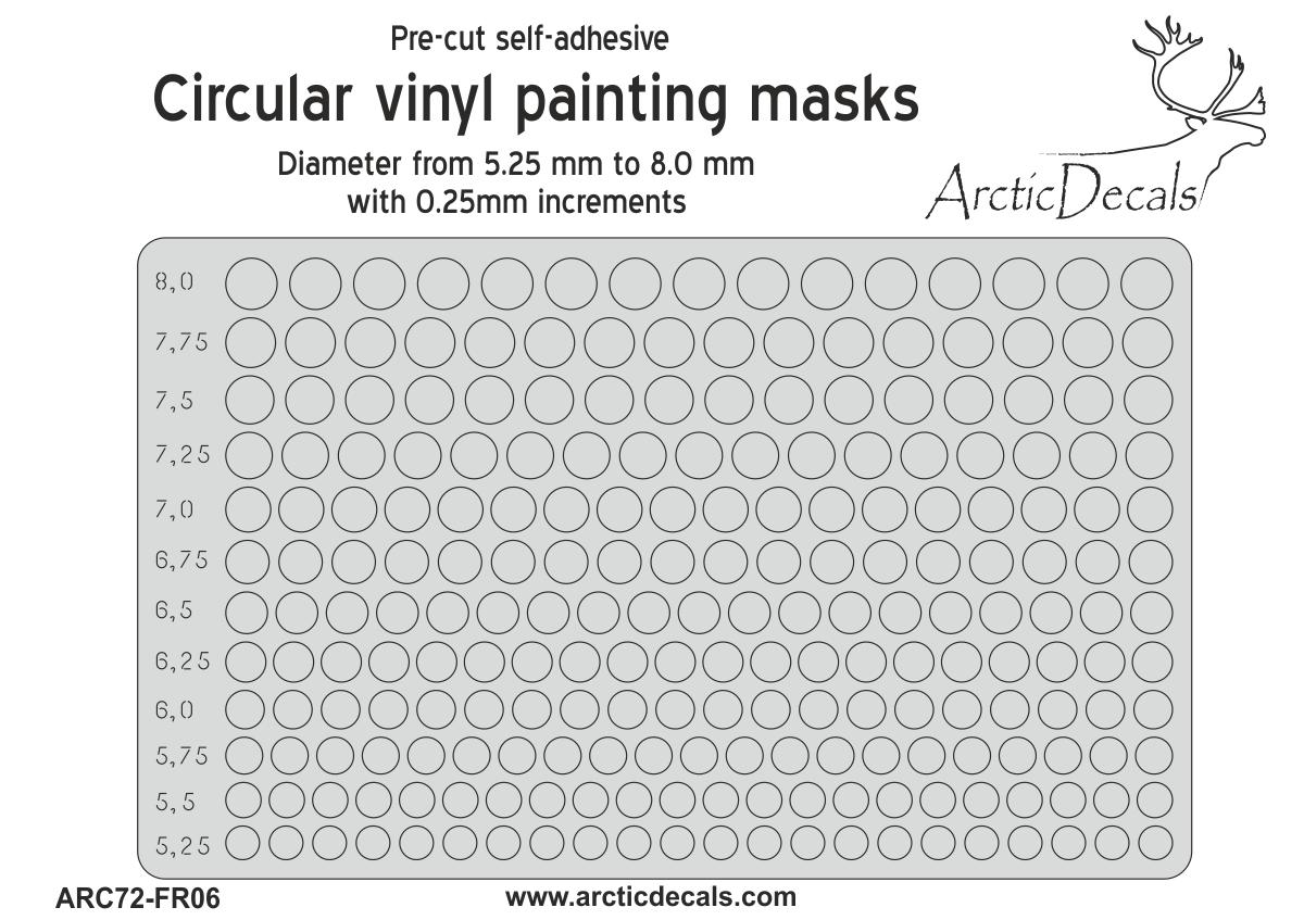
I need 2 really small (I'd say about 6mm) circles to mask off for painting. No way my hands are steady enough to try this with an exacto knife. I have one of those hole punches for leather that is really good for this kind of thing, but the largest hole is way too small. My next stop is the dollar store. They always have that one isle with the sticker packs for the kids. Any other source for this kind of thing?
Arctic Decals from Finland sells fantastic masking sets, four of them with different sizes: https://www.arcticdecals.com/tuotteet.html?id=21459/
Here's the one that would suit your needs:
I use them often, both the 'inner' parts (to cover 1/72 scale wheels) and the 'outer' parts to cover the tires.
Rob
-
On 8/27/2022 at 9:26 PM, Len Woodruff said:
I am pullng the PETG over a puck that I created for the windshield & the back light.
It says Petg should be vacuum formed when it hits around 280 degress. I used my IR gun to check. But the heat source is under the Petg so the gun may be reading wrong.
The problem is that it didn't pull around the sides with good definition so I could cu it.
I tried the sag 1st but let it get to soft and it wrinked but did comform to the puck better.
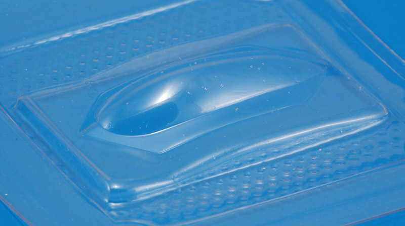
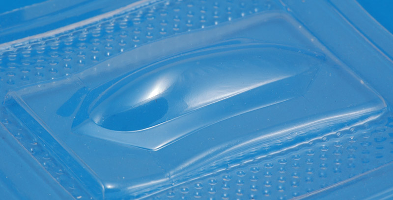
There's another limitation to take into account. At a certain temperature, the moisture in the plastic will boil and form bubbles. PET-G is quite difficult to use because of this. Drying the plastic sheets before use should help, but I haven't found an easy method for that. Here are examples with and without steam bubbles:
Rob
-
 1
1
-
-
In previous threads about the plastic color bleeding through, I reported that I read in a paint technology book that the red plastic dyes are notorious for dissolving in paint solvents, and moving into the paint. My conclusion is: use water-based paints or primers. Or at least try it on a sample to see whether it works.
Rob
-
If you're willing to try totally different 10-minute route, try this:
https://www.youtube.com/watch?v=lCKZ_fo4eW0
For the last part, you really have to crank open the Paasche. I tried it with close to ten enamel paints of different brands, and nearly all worked as advertised.
Rob
-
1
-
-
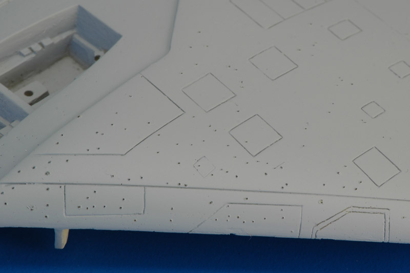
Does it look like this? I used a spray can of Mr Surfacer 1200 on this model, but then I saw dozens and dozens of pinholes in the Mr Surfacer. You can see some of the pinholes as they appeared originally in the canopy coaming area, especially at the extreme left of the photo.
I explored a few pinholes with a needle, and found a cavity (air bubble) beneath each one of them. The photo shows how all the pin holes that I found and opened up with a needle, for future filling with CA glue.
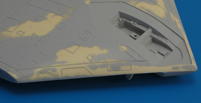
Here they are filled with thin CA glue. I did not use fillers. It was a ton of work..
Rob
-
On 6/3/2022 at 1:48 AM, Rich Chernosky said:
I have had this kit forever nad looked at it a few times but avoided because of all the bad reveiws. This time I took a lot harder look and decided it was time to see what all the fuss was. Actually I though it went together fairly well with the usual amount of fussing. In particular I liked the body fit. Attaching the wings looked the be the biggest challenge and this was eventually solved. Overall I am pleased despite the vague instructions and ancient decals. See picture captions for more description. Thanks for looking and comments welcome.
It's really nice to hear someone NOT complain about this model ? Mine also fits reasonably well. But there are some bad examples out there. I think that too short injection molding cycles are to blame for the warpage that they suffer.
I saw one in action at Spa, three weeks ago. Great sound too!
Rob
-
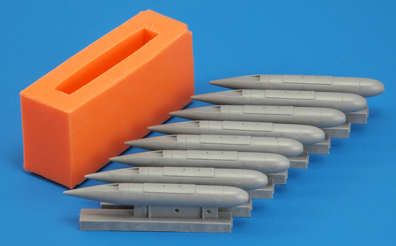
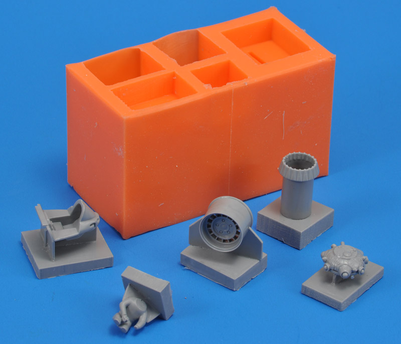
Here's another small mold that I just photographed, with the master on the left side, two castings and a painted set. They are 1/72 scale.
The mold design is not optimal: the castings are difficult to release. I could have used a zig-zag pattern, for example.
Rob
-
5 hours ago, Spex84 said:
Those are some great results! I'm intrigued by the heavy support structures holding each part in place...I haven't seen that before. Clearly it works well.
I've attempted to cast parts before and my results were extremely shoddy compared to the above examples. Thanks for the clear explanations!
You're welcome! The heavy gates (as I think is the correct word) are generally 1 mm plastic card. The thickness is required because otherwise air bubbles can get stuck in the part, being too large in diameter to pass through the gate.
Another factor is more difficult to explain, but I described the effect above. If the gate is very narrow, there's a real chance that the pressure difference during air admittance will cause the gate to (accidentally) close, and then remain closed since the pressure difference only increases. The mold is very flexible, so that happens easily. In that case the mold cavity isn't filled with resin, and you'll get a really bad casting.
Rob
-
8 hours ago, W Humble said:
Peter; not butting in! This turned out to have generated some very interesting and enlightening information, and a great graphic! That should be on Utube or something. Thanks to Rob!! I may never get that sophisticated, but then again... I have a nephew who wants to learn from my experience, and he's very tech, and a perfectionist! I'm going to will him all my model stuff, at least that my wife and/or kids don't want. He's going to teach me decal making. Wick
Maybe I'll put the graphic on my website one day. I do have web pages on decal design on my website:
https://robdebie.home.xs4all.nl/models/decals.htm
https://robdebie.home.xs4all.nl/models/customdecals.htm
( Waving to Peteski because we know each other from the Alps printer mailing list on Yahoo / Groups.io )
Rob
-
10 hours ago, peteski said:
I wonder how it would work for things like car bodies (which need 2-part molds)? I'm just theorizing since I have only been casting using single-piece open molds (like like what you are using).
I haven't cast a car body yet, and I don't know how to approach that with my methods. Maybe pressure casting has the advantage there!
Rob
-
12 hours ago, W Humble said:
I hate trial & error, but that's what I'm doing.
I hadn't spotted that line before. In that case I recommend getting:
- a single-stage rotary vane vacuum pump
- a vacuum desiccator or equivalent
- soft ~10 Shore-A addition type (platinum) silicone rubber
- relatively slow polyurethane resin, like Smooth-Cast 305
This will set you back some 250$. But you'll be able to cast resin parts as shown below.
Rob
-
On 6/9/2022 at 3:33 AM, W Humble said:
Again, impressive! I invited some inside dope on casting in several forums, but didn't catch any volunteers. I hate trial & error, but that's what I'm doing. So far, a box of failures and mediocre projects, but I'm getting better. My needs aren't high, at that, and I think if I can get halfway proficient at tw0-piece molds, I'll be okay.
I wonder if an electric fuel pump (12V, for a car) would make enough 'suck'? Thx! Wick
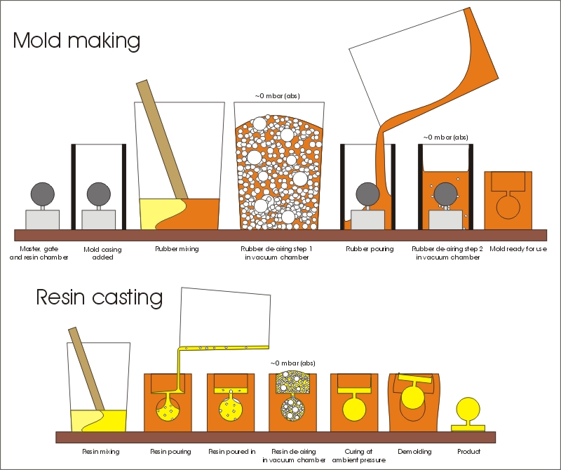
I made this graphic representation of my method. It avoids having to type a lot of text ?
An electric fuel pump? I don't think that will give the deep vacuum you need to de-air resin. As reported above, I think you need a single-stage rotary vane vacuum pump. They are pretty cheap now, 100-150$ or so on Ebay.
I completely recognise the experimenting part, it also took me years to get where I am, lacking any help, and before YouTube etc. But I taught a few club members my methods in recent years, and they hit the ground running!
If you want to go the 'American way', check out Robert Tolone on YouTube. He uses totally different methods.
https://www.youtube.com/c/RobertTolone
Rob
-
 1
1
-
-
On 6/9/2022 at 3:21 AM, peteski said:
Rob, from what I see it appears that your method is similar to pressure casting. Basically you pour the resin into the open end of the mold, then you put it in a vacuum. If there are bubbles or air pockets in the liquid resin, they will bubble up to the top. Correct? I think I like that.
Yes, corrrect! With one addition: the resin itself also de-airs during the process. Any bubbles that were added during the mixing are removed, plus moisture absorbed by the resin during the very limited open time of its containers. Plus: the mold has no cuts on the sides, I want to keep it water- and air-tight. The latter is of no importance in pressure casting it seems.
Now that I thought a bit about it, there is a theoretical difference. During the vacuum stage, most of the resin is pushed out of the mold cavity, into what I call the resin chamber, because it's foaming / boiling. Only when the air is admitted into the vacuum chamber again, the mold is actually (permanently) filled. Since the resin has to flow through a rather small gate, problems occur if you admit the air too quickly to the vacuum chamber. Air is then gulped into the mold cavity, and you'll have large air bubbles.
On 6/9/2022 at 3:21 AM, peteski said:I wonder why it is not more popular in USA? It likely takes some time to evacuate the air. What is the setting time for the resin you use?
I wondered about that difference too, it's fascinating. Maybe it's because resin casting is usually learned from someone else, and once there's an established method, it keeps repeating itself. Nothing wrong with that of couse. I developed my methods by studying mainly East-European resin parts. AFAIK they all use vacuum casting.
My resin has a pot life of 7 minutes. That's just enough for mixing, transfer to the vacuum chamber, 3 minutes of de-airing, and returning fairly slowly to ambient pressure. Air rushing in can blow resin out of the mold, and in extreme cases the molds can be 'sucked closed'.
On 6/9/2022 at 3:21 AM, peteski said:You likely also vaccum the liquid RTV when making the molds?
Correct, you need a vacuum set-up anyway to degas the silicone rubber. I think that is done in both the European and American styles of resin casting.
Rob
-
I've been hobby casting for 25 years now, and indeed this might be a bit ambitious if you're starting. Plus: my vacuum casting methods are 'European style resin casting' whereas the 'American style resin casting' is pressure casting. Therefore you will probably get very different comments from American modelers.
Here's a recent mold with some castings. Note the severe undercuts, made possible by the soft 10 Shore-A rubber. There are no knife-cuts in the rubber mold, that would lead to air leaks.
If your equipment isn't operational yet: for this method you need a pretty deep vacuum. If ambient pressure is 1013 millibar absolute, you need to go lower than 1 millibar absolute for the resin to de-air properly. You can translate these values in units of your preference. I *think* you need a rotary vane vacuum pump for that - AFAIK membrane pumps don't go that deep (maybe double stage membrane pumps do). Check the specs of your pump.
I use a 'vacuum desiccator', lab equipment, but you can also use steel pans, pieces of pipe, etc. But: be aware that an implosion is just as dangerous as an explosion: the shards will first move to the center, pass each other, and then move outwards like in an explosion. I've seen photos of sharp pieces of plastic embedded in doors after a vacuum implosion.
Rob
-
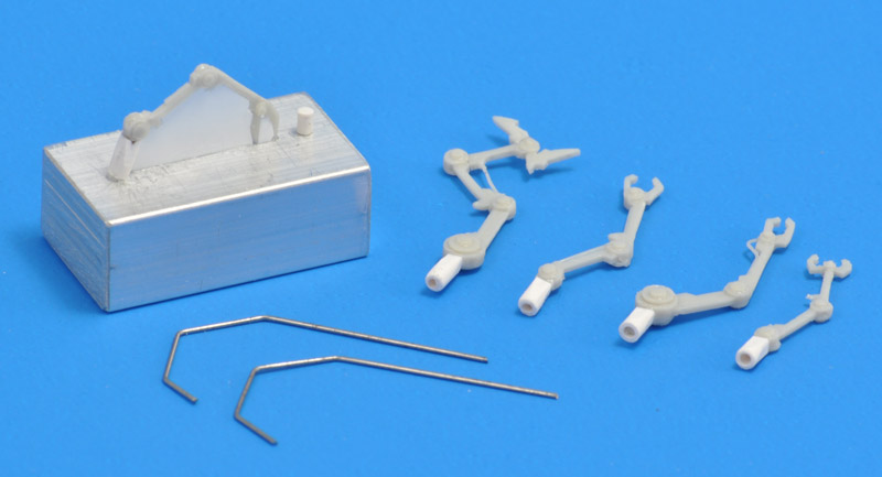
I use one-part molds and vacuum casting. I recently cast a very delicate part, to embed a steel wire in it. Shown on the right is the 'master' part, to be poured over with silicone rubber. I used very thin plastic card to 'fill the gaps'. Maybe you could do something similar for your headers? Your methods are probably totally different, I can't judge whether this will work for you.
Rob
-
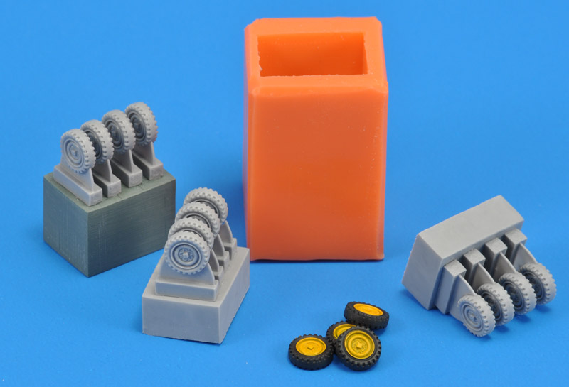
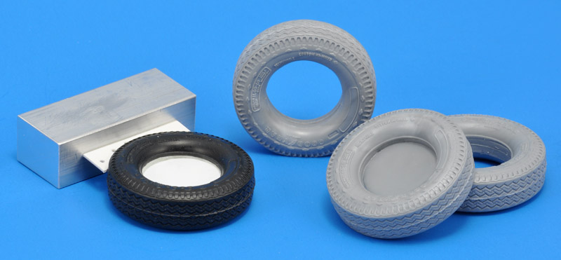
You can also make a one-piece mold - I recently tried that, and it worked very well. I wanted to see whether resin tires would be an improvement over the vinyl (?) tires from the old Ertl IH Transtar truck. I made a mold using the set-up seen on the left; the tire itself was filled with Apoxie clay before, and fitted with an 0.5 mm disc. The resin copies came out fine. I use a vacuum casting set-up.
Rob
-
2
-
-
I would recommend watching this video:
https://www.youtube.com/watch?v=lCKZ_fo4eW0&ab_channel=AndyX
Using this technique, I finally managed to spray enamels without any orange peel, super gloss, every time. But you do need to crank open that Paasche H !
Rob


Question about the 'Duel' tank trailer
in Model Building Questions and Answers
Posted · Edited by robdebie
Recently I obtained the Lindberg 'Dodge L700 Tanker' model (73072), so I could finally start work on building a 'Duel' truck. I'm using the 1984 FSM drawing by James Stevens as my main reference, plus the 'Building The 'Duel' Truck Pt 2 - Scratch Building The Tanker Trailer' video by TrekWorks, and screenshots from the movie.
I started the construction of the tank, but ran into a problem at the front. The kit has a faceted shape on the lower side, but I want to make it a elliptical shape, since that shape can be seen when the truck is down in the ravine. I plan to cut out the faceted part, and replace it with curved plastic card - not a big problem.
My question is: what are the most likely cross-sections at various points? The real tanker-trailer has an eliptical shape front to back, judging from the shapes of the front and back bulkheads. The Stevens drawing has the same cross eliptical cross sections at both ends, and a slope behind the hitch, that can be seen in the movie. Therefore the shape in the middle should be a modified elipse. Does a dip in the middle make sense, for draining the tanks for example?
However, this screenshot suggests flatter front section.
So, alternatively, the rear half of the tank could have a constant cross section, and the section above the hitch is an elipse flattened at the bottom side. I've drawn it here:
The reason why I'm afraid to make a mistake is that the trailer might be too high for the truck's hitch, leading to an inclined trailer. And I don't have the truck yet to make a test fit.
Maybe someone with real-world tank trailer experience knows? Thanks in advance!
Rob