Egilman
-
Posts
80 -
Joined
-
Last visited
Content Type
Profiles
Forums
Events
Gallery
Everything posted by Egilman
-
Thank you Anton, It's taken a while to get the process of working on a screen rather than paper sorted out, but I think I'm getting the hang of it....
-
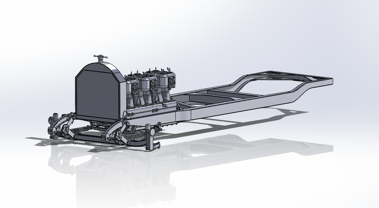
Hi Randy, Thank you and Welcome to the thread... Haven't decided if I'm going to make it printable yet, there will have to be some major changes to do so.... Right now I'm just trying to capture it as close as I can figure it out... This is her status as of today... (just a few minutes ago as a matter of fact) As you can see the emergency brakes are now connected and I've finished sussing out the base bracket for the brake lever and am working out the shifter bracket.... Scale will be the main issue, there are too many parts that won't print right now cause they scale down too small, (she is drawn at 1/1) Almost everything would have to be adjusted once a scale is decided upon... It is a long term project.... I'll be plugging away at her till she is done or I'm done..... (whichever comes first) Thanks for commenting and feel free to ask questions... It helps the motivation.... EG

-
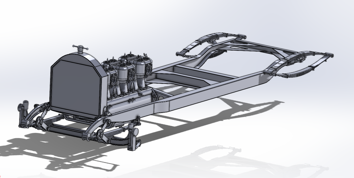
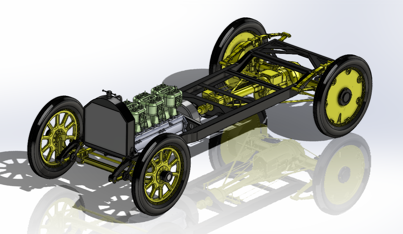
I was taking a break and playing around, Got the thought of throwing a bit of color on her to get a feel for the scheme.... These are not accurate colors but close and the only judge is what we have today at the museum so that is what I will probably run with when the time comes... But anyway, this represents an idea of where I'm going with this....
-
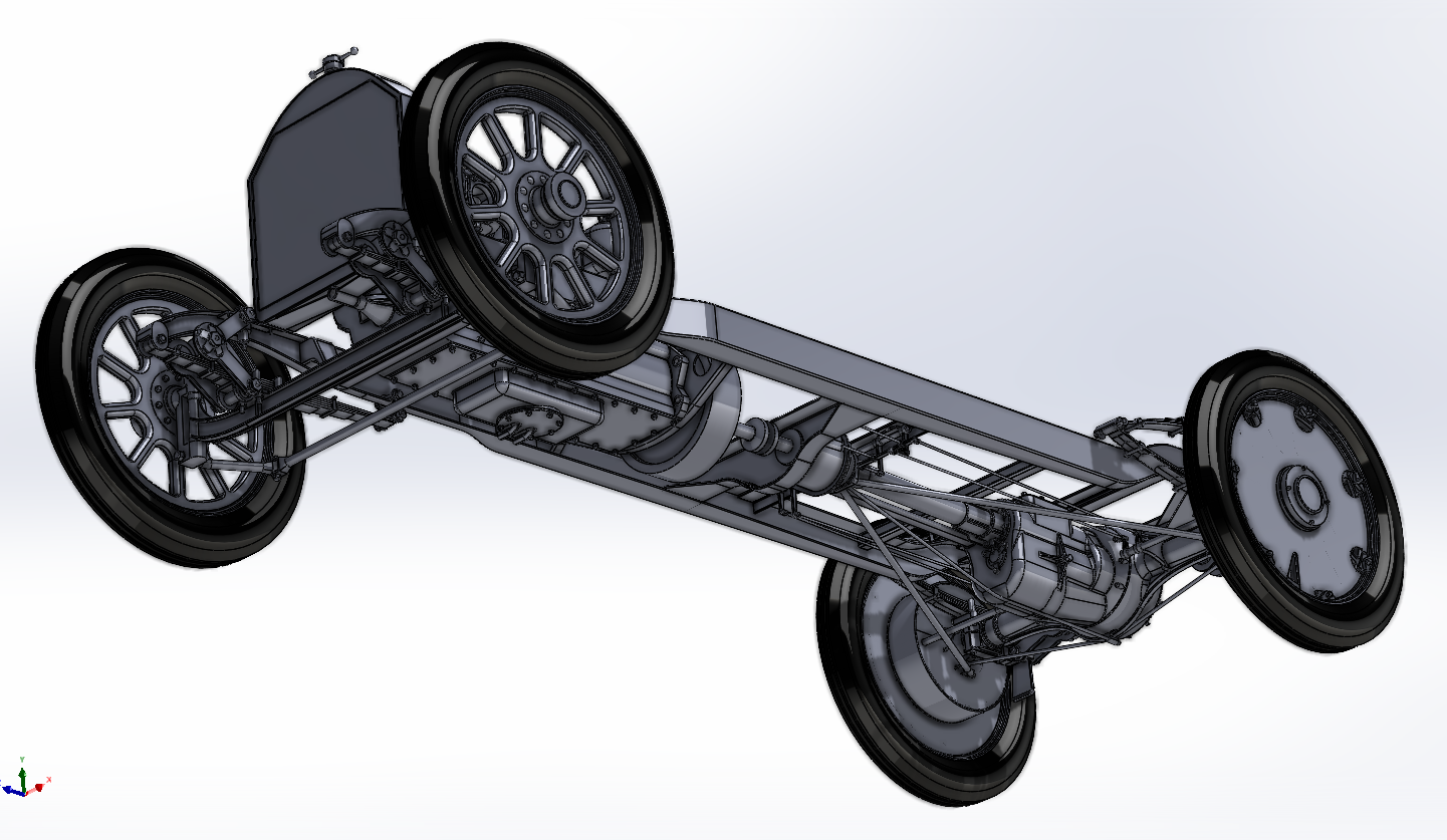
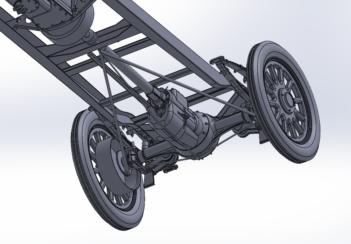
Making progress my friends.... I did the Drums and then said what the heck I'll finish off the rear wheels..... And I went ahead and colored the tires black, it looks better this way.... Just about done with the rear end.... Unless I come across something I missed it's pretty well finished.... And a bottom view.... Still need to detail out the rear wheels, screw heads and the inner portion of the rim clamps and stuff like that, but except for the small stuff, essentially they are done... Onwards...
-
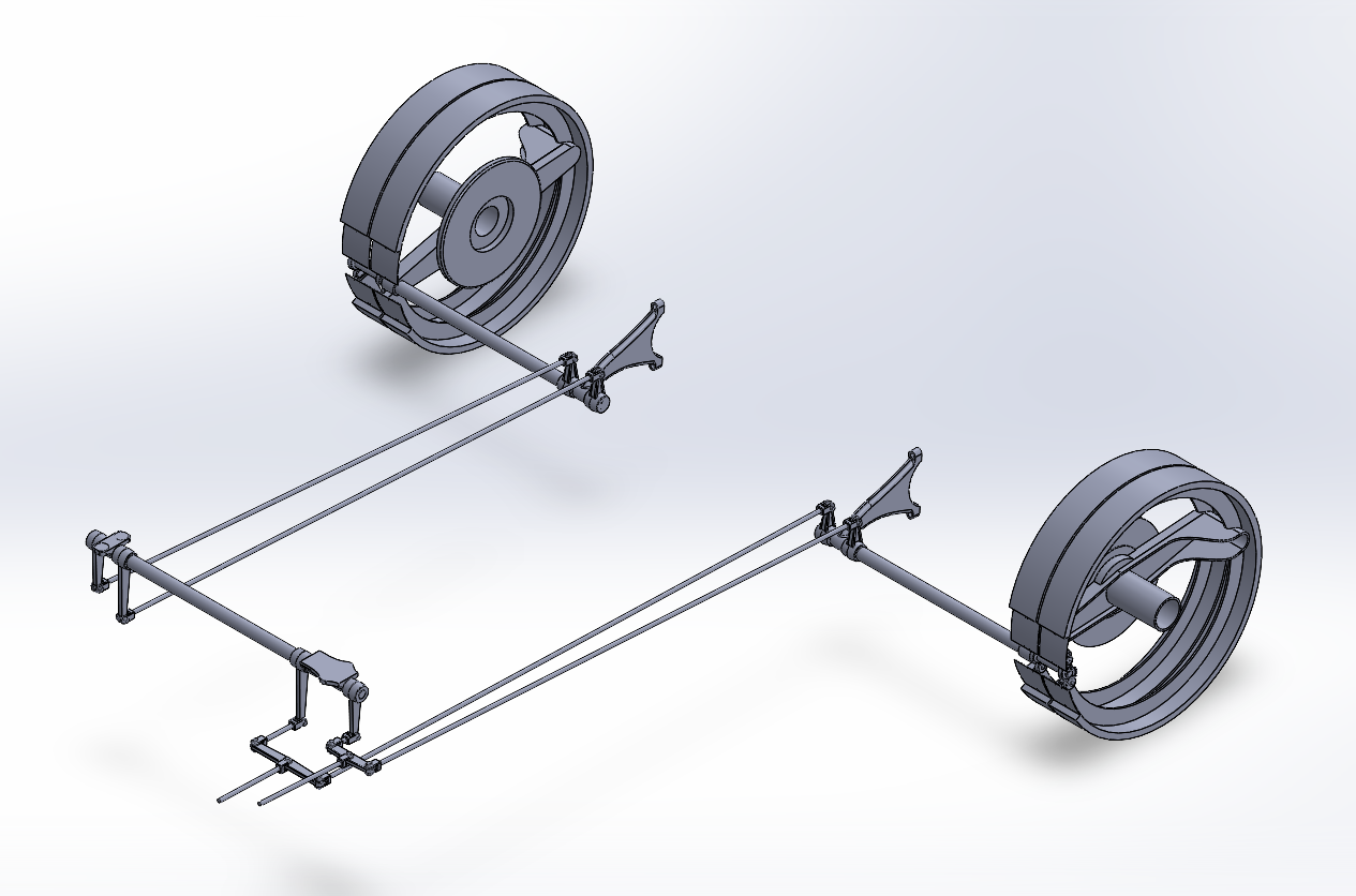
Another small update.... The Brake Rods.... Input is at the lower left to the equalizers then back to the left side brakes directly and to the right side brakes through the intermediate shafts... Probably time to figure out the Drums and get them corrected... Then I can get back to a rolling chassis.... {chuckle} Anyway, Onwards....
-
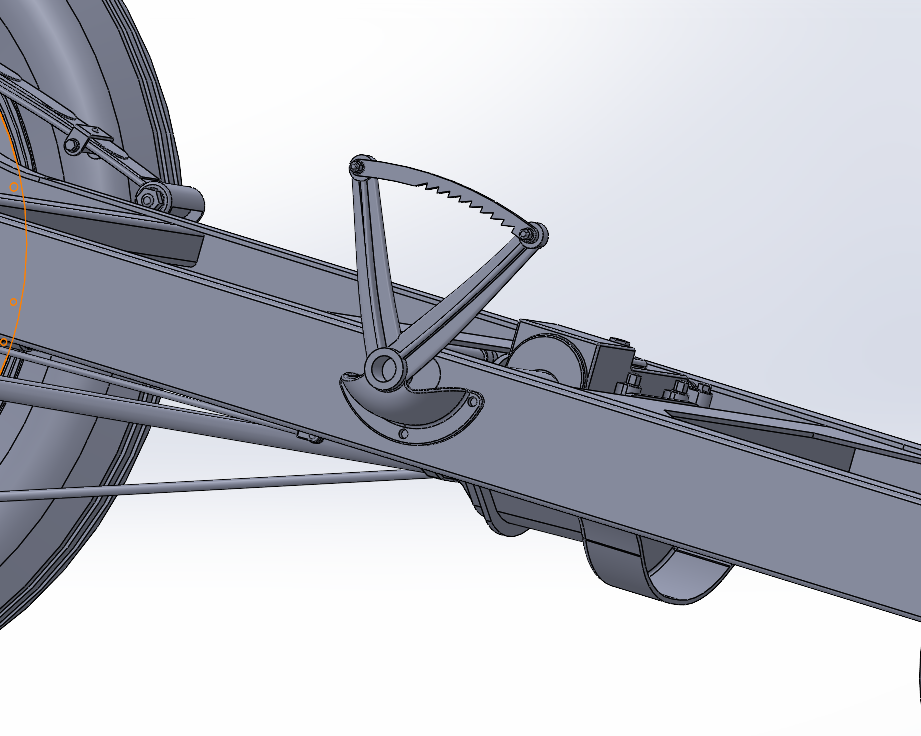
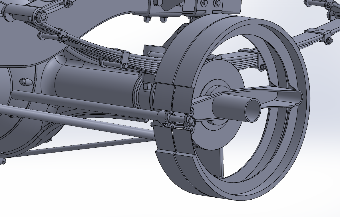
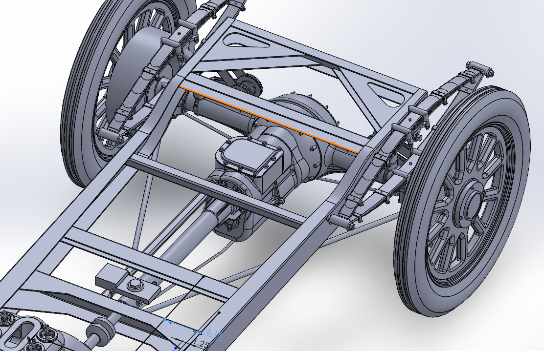
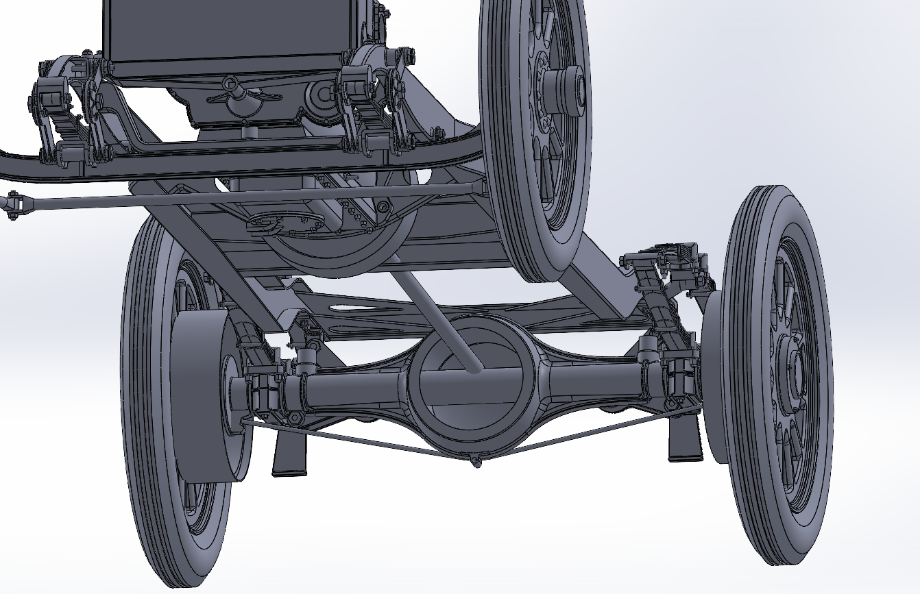
Update.... Brakes... The Wasp had two independent braking systems, the Emergency/Parking brake and the driving brakes.... On a standard Marmon 32 the brakes were mechanical and independent in nature, the Parking/Emergency brakes were actuated by the lever outside the cockpit on the right side of the chassis... the Driving brakes were actuated by a pedal on the right side of the cockpit floor.... The Marmon Wasp however had the Emergency/Parking brake on the right side of the chassis identical to the standard Marmon, but no cockpit brake pedal I can find from numerous pics of the interior layout... The only thing I can find are artists renderings of the chassis which seem to show the Driving brakes synced up with the clutch, when the clutch was depressed, the driving brakes would actuate the more you depressed the clutch pedal... It is the only explanation for the lack of a brake pedal in the cockpit.... It also conforms to the accelerator configuration the pics show... (more on this later when I get to the driving controls) But first, we have to locate the actuating rods at the rear of the car.... The only way to do this accurately is to build a sample representation of the actual brakes.... The inner brake shoe was actuated by the lever, the outer by the pedal... Each shoe was a single piece expanded by an "S" cam working against rollers affixed to each shoe. (same system used on heavy trucks to the present day only the brake rods are actuated by an air cannister) In 1913, Marmon went to split shoes instead of one piece, (upper and lower half shoes) but in 1910/11 they used single shoes.... Made for a very simple installation... The rod you see from the "S" cams heading towards the transmission was the actuating rod for the brakes, it consisted of a torque tube riding on a shaft... The torque tube actuated the inner shoes and the shaft actuated the outer shoes... They were supported at the end of the shaft by a bracket that bolted to the Axle housing allowing two lever arms to attach to the tube and the shaft... Overall view... I haven't got to the actuating rods yet as I'm still sussing out the equalizer configuration, each system used equalizers to balance the braking force from side to side, this is the purpose of the crossmember right behind the thrust bushing housing... It carried the intermediate brake tube/shaft that was actuated by the lever and pedal... The outside diameter of the brakes was 15" measured to the friction surface and the drums were 16" made of pressed steel and polished inside, they were affixed to the wheel hubs and were removed with the wheels... Anyway, now working out the brake actuating rods and shafts, eventually getting to the actual pedals, (both brake & clutch) and the brake lever which will take me to the shift lever as well... Onwards.... I hope everyone is enjoying this design exercise.... Thank you...
-
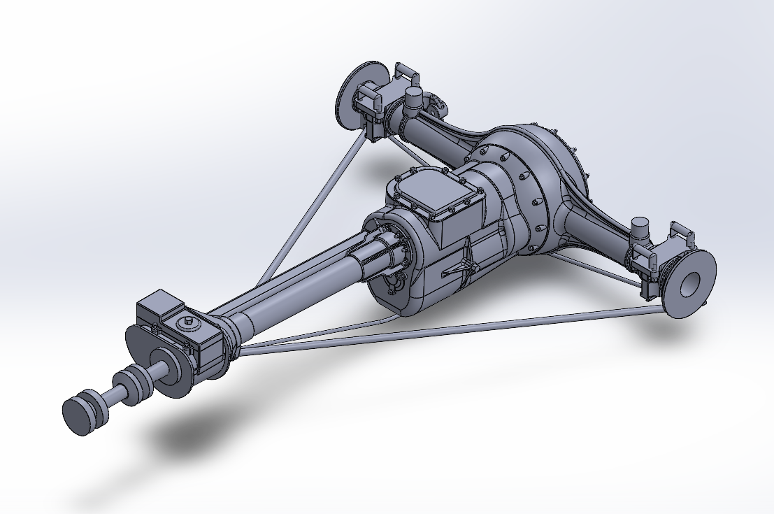
Ok, Another update... I think the Driveline Package is basically done... May need a bit of tweaking as I learn and discover more about the technical side of the car, but that is the basic transformer part, transform the engine rotation to go that-a-way right now.... The Rear End is about 95% accurate to images, the Transmission & Drive Tubes are about 85% accurate the Truss Rods and Braces are about 75% accurate, And I would guestimate that the Thrust Carrier is probably 55% accurate it's the part I had the least amount of info on, a lot of engineering deduction of how it probably been and what it should have looked like... It will have to suffice until more accurate information surfaces.... I'll probably take on the Brakes and their associated rods and cranks... Yes the Wasp had dual acting mechanical brakes, only on the rear wheels mind you, but with four shoes per wheel, (standard Marmon practice) she could stop pretty fast.... Any way Onward the odyssey goes.... EG
-
Well, another update... Transmission version II is finished, probably going to have to do a version III, feels a bit out of scale... (too fat) The two diagonal braces and center truss rod is installed.... I think I'm going to suss out the thrust bushing first before taking a third look at the tranny.... I need a change of pace..... Onwards....
-
And an update.... Transmission.... Mounted to the forward part of the differential... It could not be removed without disassembling the Differential.... (the lower round of anchoring studs came from the tranny case into the differential housing and were nutted on the inside) Three forward speeds and reverse non synchromesh.... This is a work in progress at this point... Some details are on it, but still working out the basic shape... What was interesting from this design is the tranny could be disassembled thru the differential housing.... Made for very quick repairs if necessary.... Any way I'm still working at it.... Thanks for the likes and comments they are appreciated... Onwards... EG
-
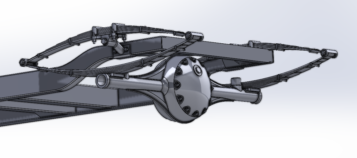
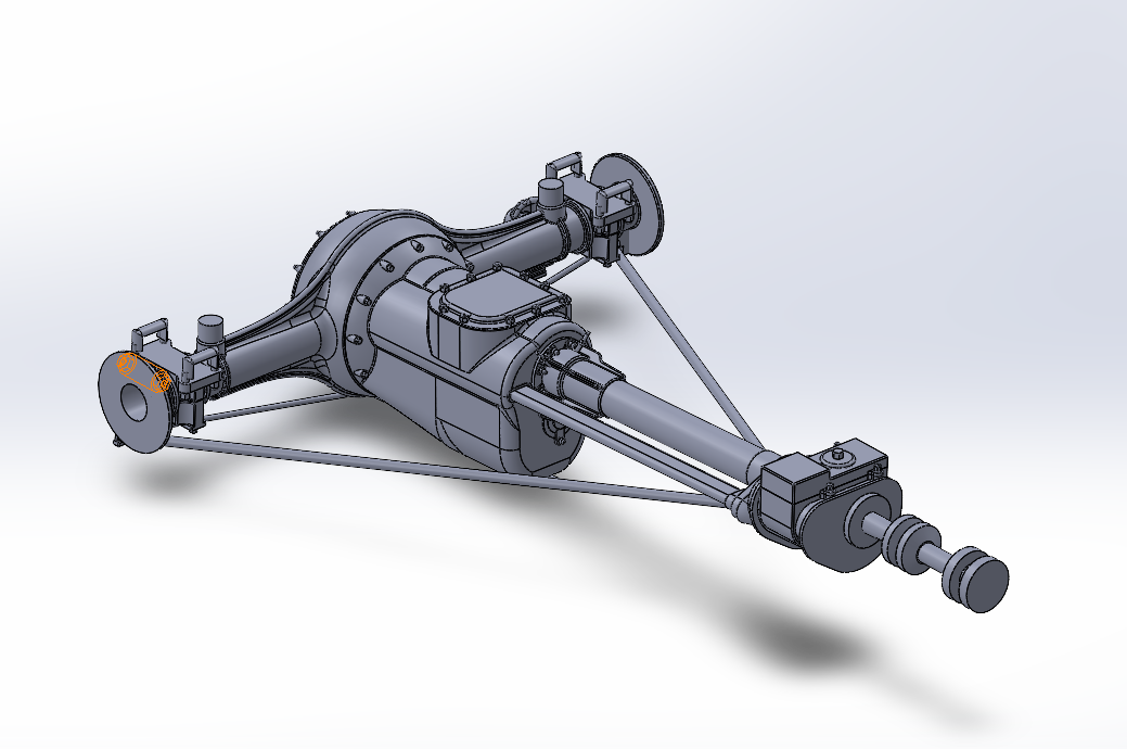
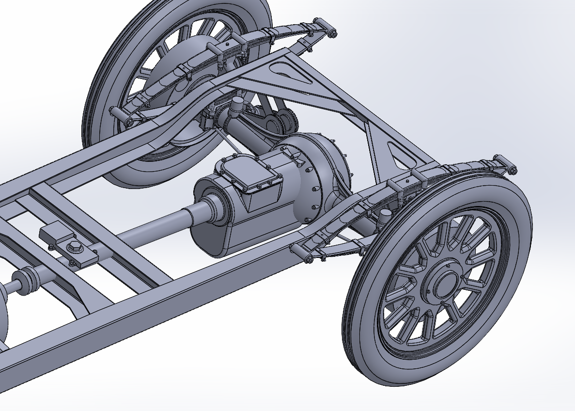
Well chemo just about kicked my butt for the last few days, but I finally got something done.... All Bolted, Nutted and Shackled up, the Rear End is now an attached part.... The bottom truss rod is also installed... I reduced the flange plates on the ends of the axle housing in preparation for making the brake shrouds, (those big drum looking things inside the rear wheels) more accurate.... I first have to locate the brake support inside the brake drums.... I'm not going to model the brakes themselves as they will never be seen, but I need the bracket cause it carries the brake rods and torque tubes for actuating the brakes along the front of the axle... You will definitely see those when looking at the chassis.... Next up is the transmission... It bolts to the front of the differential carrier and has a thrust tube that meets the thrust bearing at the mid frame crossmember, there is also an oval shift rod tube that parallels it along the right side... The driveshaft you see in the picture is a placeholder.... (just keeping everything properly aligned) Still making progress..... Onwards....
-
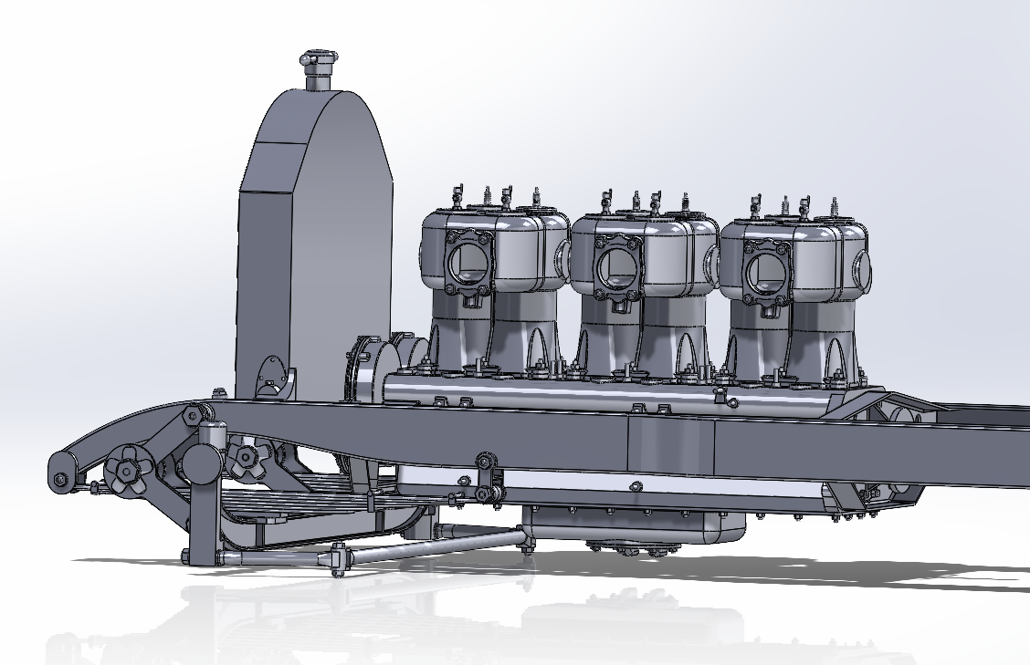
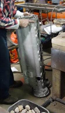
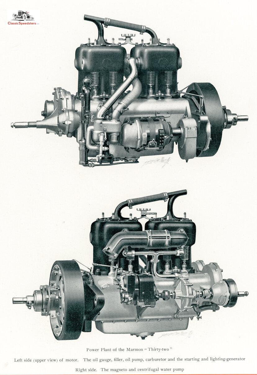
Thanks, My references for the engine are nothing but the pics I've been able to collect off the web, I've used those for the actual in car configuration as it was a one off design specifically for the Wasp.... Although is was based upon the Marmon 32 engine.... The clutch is also a standard Marmon designed part, originally a 1909 clutch, that was changed to a 1910 clutch at the start of testing the car.... The design is taken from the pictures in the Marmon advertising manual of 1911 and is only the exterior shapes... I've since obtained a more detailed blueprint cutaway drawing of the clutch from 1911.... The exterior images are quite accurate as far as I took them.... The second image above comes from the 1914 Model 32 ad manual, and you can readily see the changes made from 1911 to 1914, the water pump is the same, just changed hands, left to right... as with the Magneto left to right but a newer model as well.... The block designed has changed as well.... The rear engine mount is no longer a steel stamped channel, it has changed to a steel casting... They made a lot of changes between 1911 & 1914 The image below is from a 1911 Marmon 32 that is still in existence today.... (restored and running, it is obviously modified for electric start) That's the source for the shape of the sump cover plate and it's oil tubing connections.... And is a certified known example of a 1909-11 Marmon 32 engine in original configuration.... The oil pan is exactly the same as a standard Marmon 32 oil pan, a machined casting except they extended the ends to cover the full length of the six cylinder block... They also revised the block a bit, widened it to use a larger crank circumference for stronger bearings... The info I got on the shape of the pan is derived from the many engine pics of the car today, and using Gimp to enhance the images to bring out the background details, there is no good shot or drawing of the actual pan.... I also used a pic of the pan on a 1911 Marmon 32 to get an idea of the center sump where the oil line connections are made.... So, my rendition is a derived part.... I have a pic of the block when it was being repaired after the 2011 celebration of the 100th year of Indy where she threw the #2 rod and busted a hole in the aluminum crankcase..... You can see the bottom side is one flat machined surface, which matches the details I've been able to glean from the other images of the museum car.... You can see where the earlier patch weld job was done that patch job failed and weakened the block even further, so they stripped it down and sent it out to have it professionally repaired... Today you can't even tell it was broken, it is actually stronger than when originally cast... That's the only pic I could find of the actual block, as I said it's a one off, the only one in existence and it's substantially different than the standard model 32 engine.... I've been researching this car for a while... And I still don't have enough sources... I have decent coverage of most of the wasp or the car it was built from, what I don't have are images of the middle of the frame and the parts that reside there, there is a part that sits just behind the mid frame member (thrust cross member) which take the load from the Axle/Driveline housing and transfers it to the frame while keeping the output shafts from the clutch aligned with the driveline, it is where the second universal is located... I only have images of the top of it and blurry images of it hanging below the frame of the car... That's is probably going to be another derived part... You carb look fantastic... Very well done, and an accurate representation of it...
-
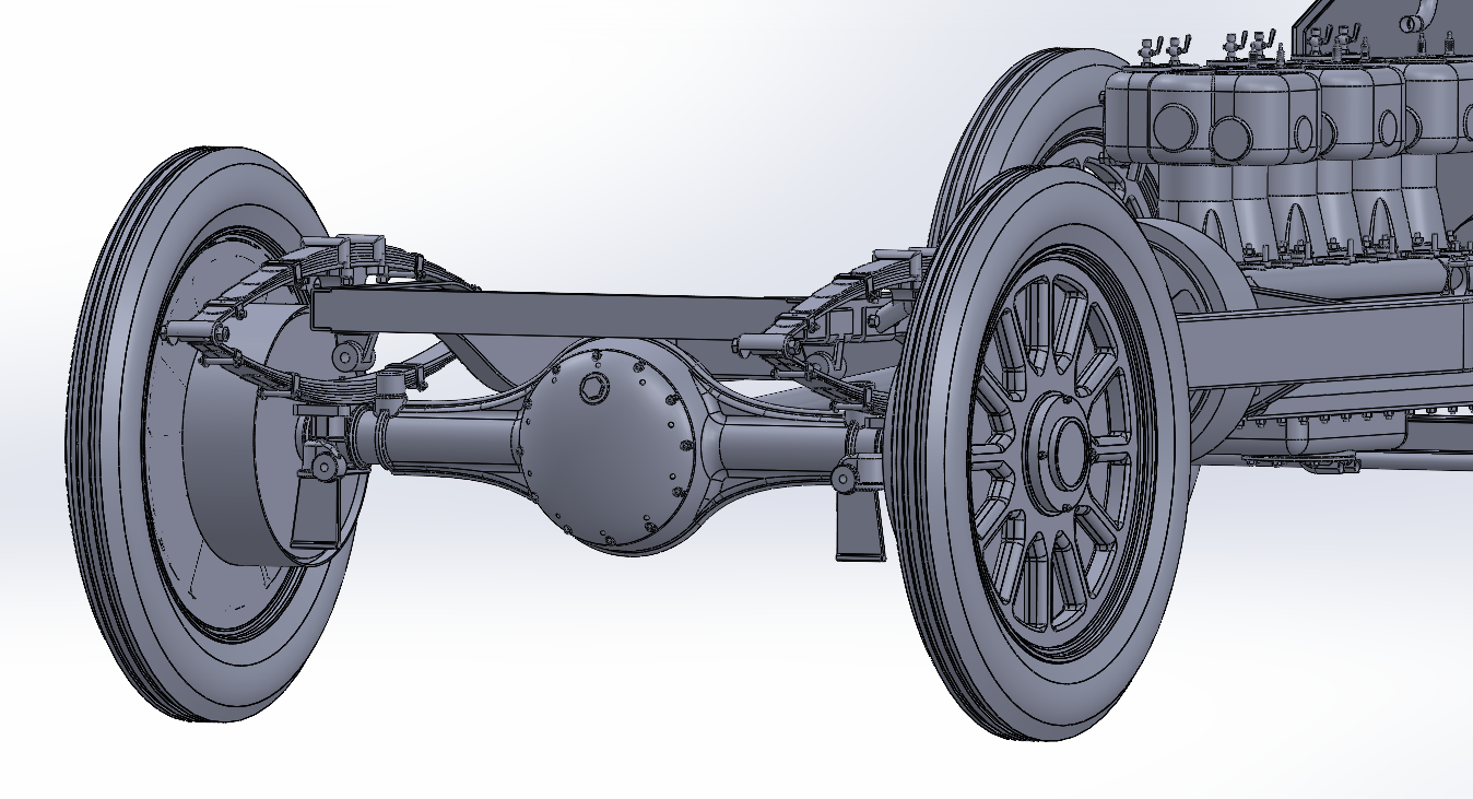
Doing a bit more, This took a little bit of time cause I had to find a few more detail images.... then, figure out how to represent the parts.... Axle Mount Plates and Rear Shock Absorber mounts.... The lower Axle Mount also incorporates the Shock Mount and Jacking plates The upper shock mount hangs off the frame.... The images I found are detailed high res images which show the truss rod attachment points and gave me a much more detailed look at the Differential Cover.... This allowed me to adjust everything accordingly... Next up is the spring shackles and bolt heads for all the mating parts.... And adding the 1/2 inch truss rods.... Onwards....
-
Well, the die casters have done this car, (inaccurately I might add) and a couple of limited edition kits have been made, also inaccurately... There is a 1914 Mercedes GP winner out there, and the maker, (FPP, out of Portugal I think) also makes the 1914 Indy winner version in resin.... (almost identical) I have a copy of it on my shelf... It's gorgeous... That's my inspiration for this one, and several others that haven't been modeled at all... The crazy idea is to do all the Indy 500 winners, but I really don't think that is going to be possible, there isn't enough time left to do that... I haven't decided if I'm going to kit this one for 3D printing yet, but the thought has occurred to me... I agree no one is going to make an injection kit, there just isn't the mass market for it... Sometimes model manufacturers miss the boat, they are famous for it...
-
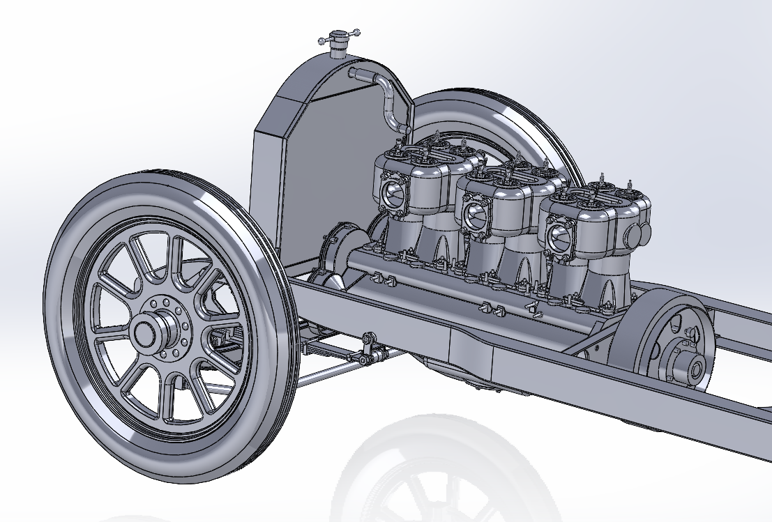
Well, I was piddling around with this trying to figure out which way I wanted to go... I did the upper radiator tube and then though that it would be much better if I finished out the driveline so the Rear axle will get completed.... So I installed the Flywheel and Clutch.... Next up is the shift mechanism, and the shift gate, and the part of the driveline that reaches the thrust bearing.... (with two universal joints) With that I'll be able to set the final position of the load crossmember and the pivot point of the rear suspension.... Onwards....
-
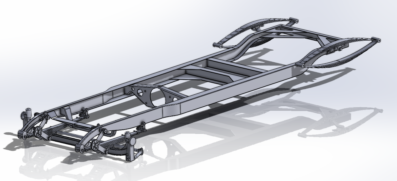
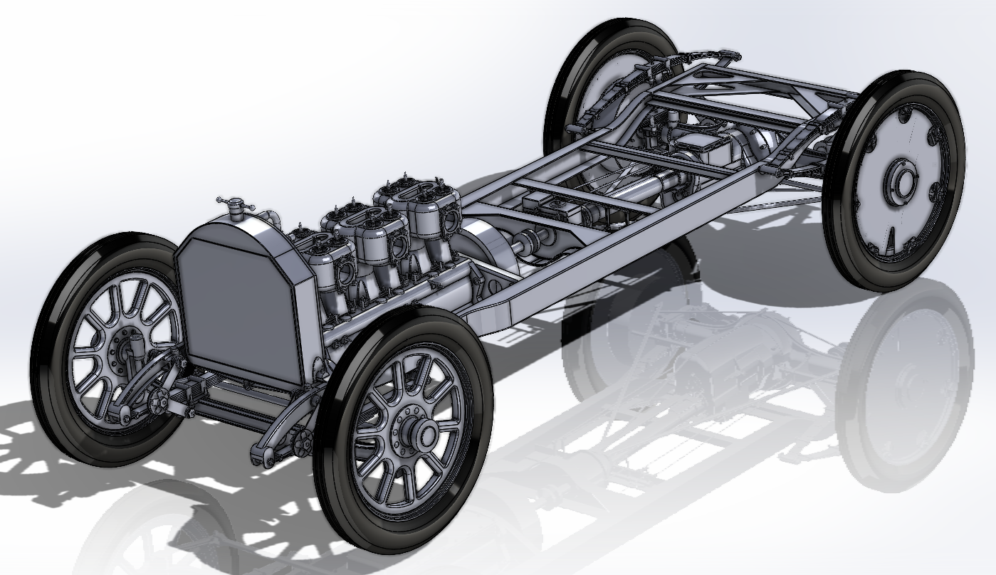
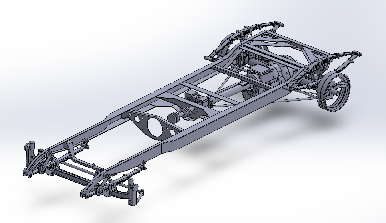
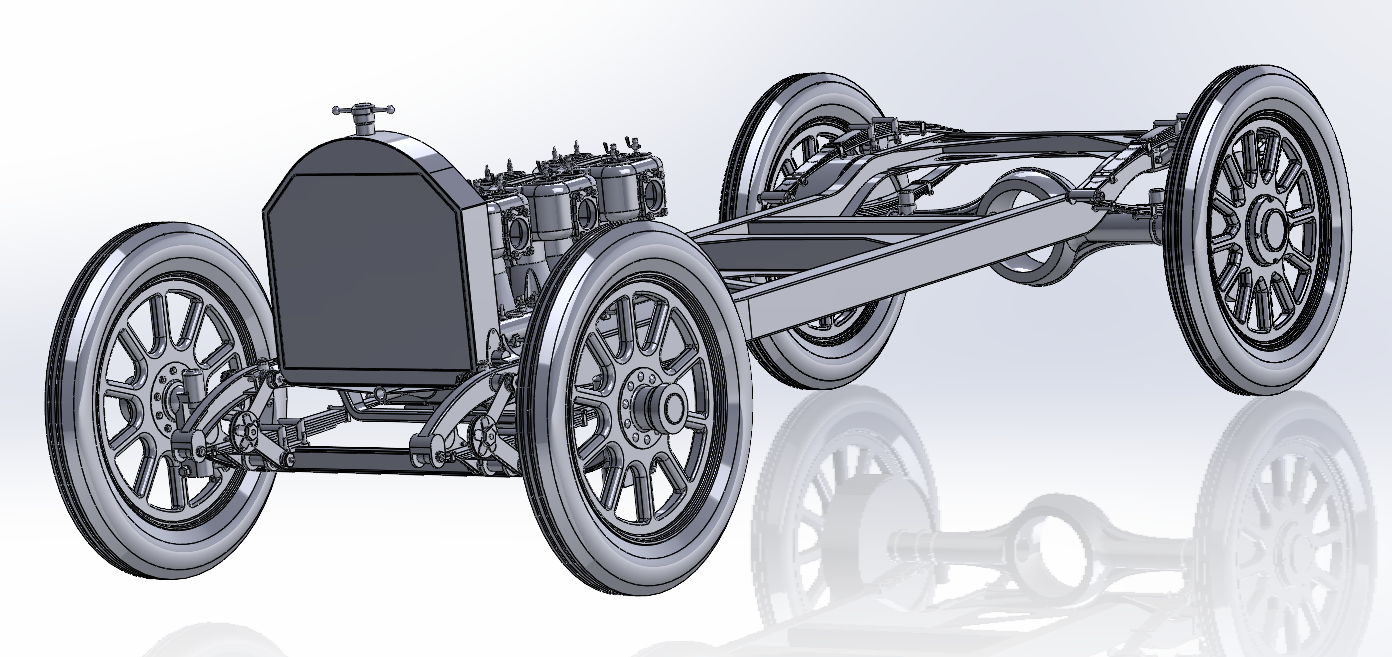
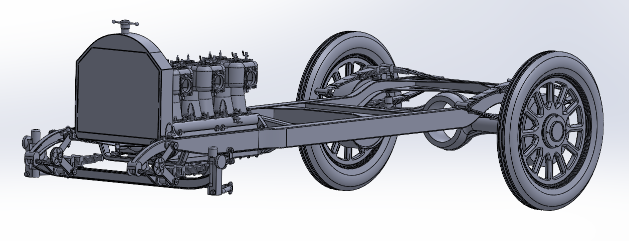
And we now have a rolling chassis.... Still needs a LOT of details and tweaking before she's a finished chassis.... But she's got good rubber all around now... (and I went ahead and tweaked the rear springs, that's what took so long, I had to rebuild them from scratch) Onwards
-
And now with tires!!!! 1911 version of Goodyear 34x4.5 racing tires... (actual dimensions: 35.125x4.625 inches inflated on 25 inch rims) Looks like I'm going to have to lower the Axel some more, at least an inch to account for the forward lean.... (going to require another re-configuration of the springs, I think increasing the curvature a bit) Now on to the front end...
-
Well, another update.... A redesigned/revised Rear End, relocated Rear Springs and Rear Wheels and Rims from the 1910 version of the car.... And yes she carried 12 spokes on the rears No tires yet, and details are still lacking but I'm making headway.... I do have the 1/16th inch steel plate reinforcers in the file, just turned off at the moment, details needing to be done are the lug plates and clamps for affixing the Tires/Rims to the wheels.... I'll probably go back to the front axle so I can mount up some front wheels and settle the ride height/forward lean issue..... Onwards...
-
Thanks Trevor! That one I did some Gimp work to make it more useable.... It is a nice shot... Lotsa details Everything I've put up has been published on the web, I have some I can't put up and I know the difference, but if anyone claims a copyright to any image I post, please take it down... OR, tell me and I will take it down... Some of them I have done some work to to heighten their usefulness in dragging out details... I have over 100 images of the Wasp and Marmon Speedsters in general including a Marmon sales brochure from the period for the speedster showing the internal mechanical layout... All of them obtained off the net, public fora and the like and most have been up for months... (probably a pretty good fair use claim) BUT! no matter, If anyone wants me to take one down, it's gone... I won't steal anyone else's work or property... ISM is a good source so is Classic Cars... and then there is the old school source the local library... Good Luck...
-
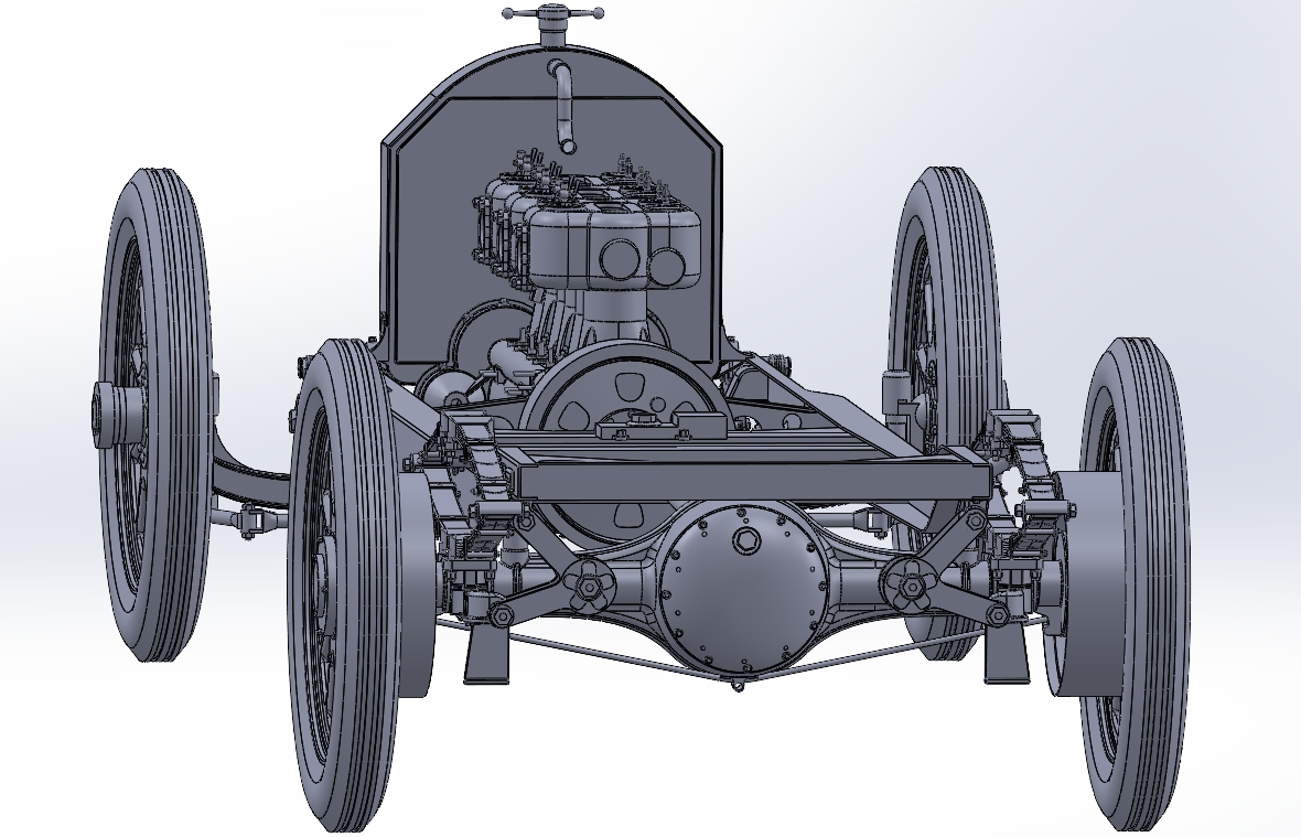
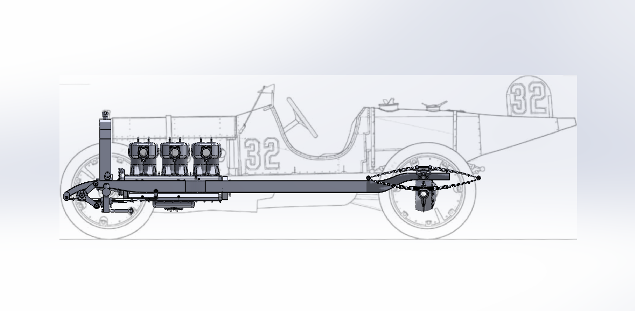
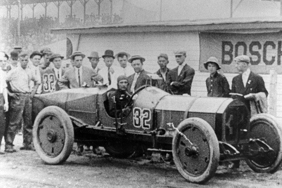
Hi again, have been a little bit under the weather as of late so not much going on... So I thought I would show some of the work that has gone into this.... The Car, the Marmon Wasp, is part of the HAER collection of outstanding American Engineering.... I have the drawings they made of the current car I know representative only not real accurate... (but good for use in comparable proportions) Here is an image of the work so far superimposed on the left side drawing of the car.. The drawing shows a forward lean to the chassis, and yes the car does have a 1.23 degree forward lean... (but it's a lot easier to draw it flat on plane) There are other discrepancies between the model and the car of today... I'm building it as close to race day as possible, and the drawing represents her as she is today... I do have the basic dimensions of the car, 115.5" wheelbase, 187.5" overall length, 56.5" track at the rear wheels, 69.5" overall width, (measured at the front wheels) The overall height is 59.5" at the fin, (and no the fin doesn't lean forward as drawn even on the car today) and 56.5" to the top of the rearview mirror... (the first rearview mirror ever used on a race car, some claim used on any car but research hasn't been able to nail that one down) According to Ray, the mirror wasn't much use, it vibrated so much it was almost pointless... Besides it was only installed to get the car around the rules about having a mechanician ride around the track with the driver acting as a spotter... Everyone else in the race except Ray had a passenger.... The HAER drawing if anyone is interested... The car as tested in 1910..... There are noticeable differences between the car as built and at the first Indy 500... The Car on race day... Anyway, this was the start of my journey in modeling this unique race vehicle.... Onwards.....
-
Thanks Steve, I don't feel so lost anymore.... I like to do detailed studies of a subject... then reverse engineer it... That was part of my first job out of tech school.... (too many years ago to count)
-
Oh I understand Dan, MSW does a similar thing.... But the info for how long it remains in place is no where to be found on the board, (and I looked) so the only way was to ask... Apologies if it upset anyone...
-
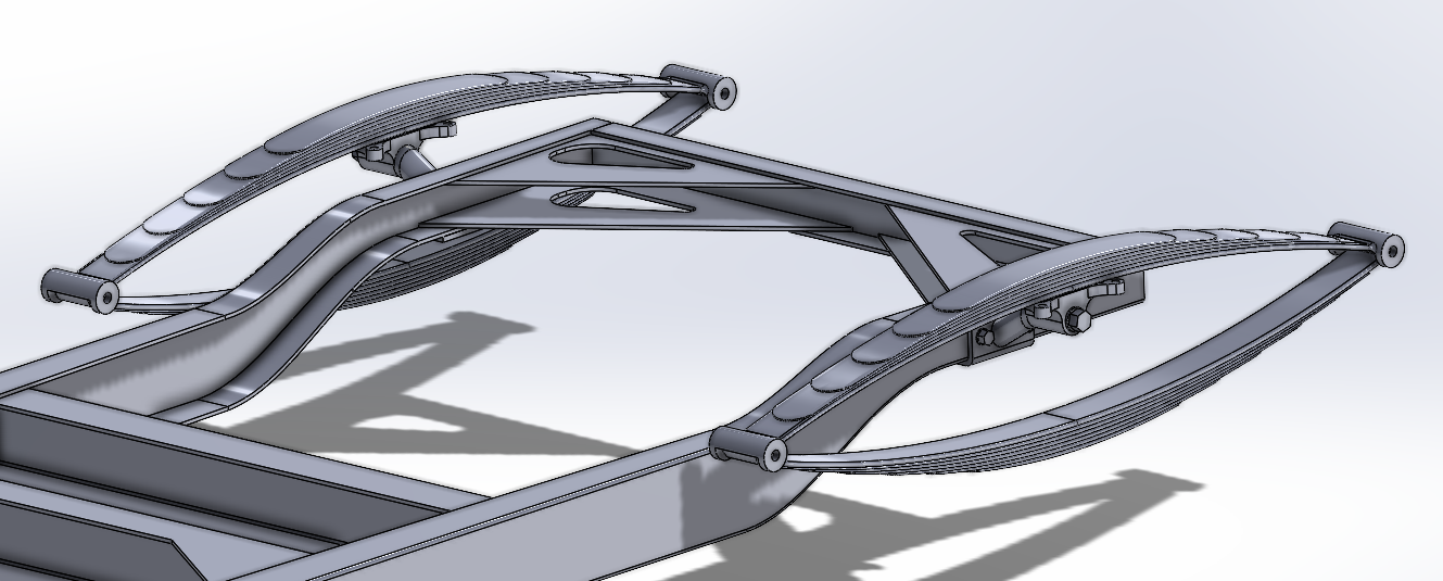
Well she's got a tail, not completely dressed for the job yet, but soon to be fit for the task.... But then ladies are like that.... (at least the ones I've been associated with) I gots a question? I don't really mind talking to myself, but since I'm the only one active in here is there a reason a mod needs to approve my every post? My bona fides should be established by now, and I can offer up references...
-
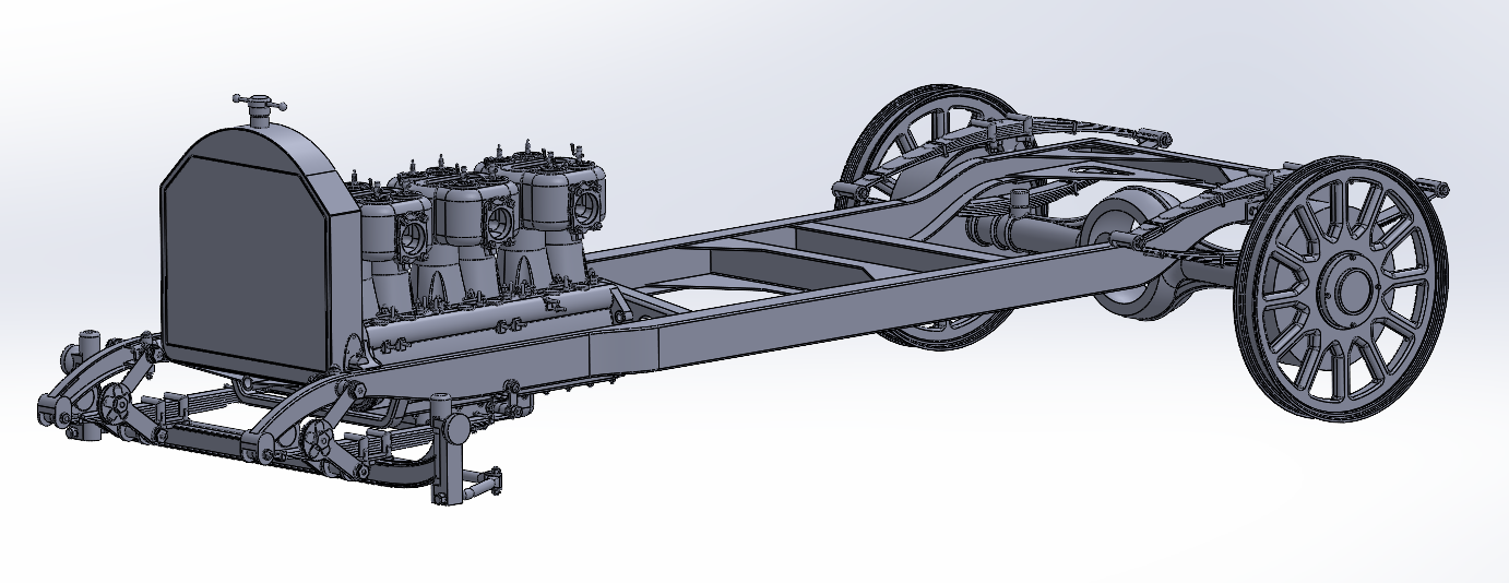
Still plugging along.... The Rear Springs took a little longer than I had anticipated..... Still need the bolts and shackles for them but once they are done, I'll move into setting up the rear axle... Once it's a rolling chassis, I can start on the bodywork.... A close-up... Onwards...
-
Yep I was collecting images for over six months before I thought I had enough to start modeling... And even then I needed to find more and really research the car... It was built off the 1909 Marmon speedster with updated 1910 parts... It qualified as a 1910 car... They didn't change the wheelbase or track of the chassis just re-arranged it... Other than the parts needed to do the rearranging and the redesigned engine it was a basic Marmon speedster... Marmon entered two cars in the first Indy 500, the Wasp and a basically stock 1911 Speedster... The Wasp came in 1st, (mostly the result of Ray Harroun's tire change strategy) and the Speedster came in 5th if memory serves.... It wasn't the fastest car on the track but it was, when driven within it's limitations, the best car on the track...(on many tracks nationwide) Here is the latest iteration.... Added the Rear Spring mounts and version 1 of the springs themselves, but I do need to rework the rear springs, right now they are a maze of small disjointed parts.... I'll keep plugging along best I can...
-
Here is the latest iteration.... Front Axle, Steering Knuckles and Drag Link.... Still need to polish it up a bit, you know those pesky details.... EG


.jpg.f6b65bd74e7593973385732f3e7a34e6.jpg)


.png.8c9e2d15b07ed291066178ce2c4d05a6.png)

.webp.d0ba80f71ed1579896bc0c04f8b1f97e.webp)