Egilman
-
Posts
58 -
Joined
-
Last visited
Recent Profile Visitors
525 profile views


Egilman's Achievements
MCM Regular (3/6)
-
Thanks John, been working on her steady this week as time allowed... Here is the current status.... Left side... Right Side... Front.... Rear... I haven't drawn the Steering Knuckles yet, but I've learned they were identical from side to side just mirrored... The steering arm was a separate part that was bolted on over the right side knuckle so it is unique to the Wasp... My previous design was of the standard steering knuckle/arm, (one part) from a standard Marmon Speedster... Your pics of what is actually on the car are a godsend for getting it right... That's what I'm figuring out now, the steering knuckles will be easy, it's the steering arm that will be a challenge... Again thank you for your generosity.... EG...

-
The basic Axel is done.... (with the shock absorber brackets) And an overall view.... Next up is the Spindles..... Onwards...
-
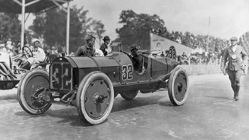
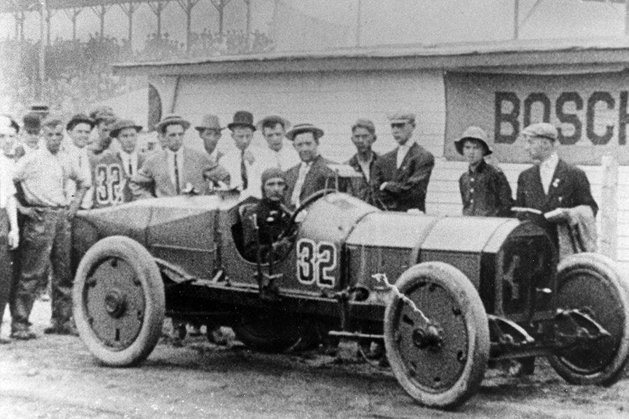
Thanks John... Yep, I saw that... The twin mount on the right side is the original, made from 5/16" steel... Day of race pics clearly show four shocks on the front mounted inside and outside the frame rails... The left side is a replacement to make her drivable made out of 3/8" steel.... It sits too far forward as well as being only a single mount.... Inner right side... Inner left side...
-
Update: Front axle... Overall, (along with the front Shock Absorber Bracket) Now to design the spindle tubes, leading to the Spindles themselves at which point I'll incorporate the camber, (outward lean) and toe-in, (narrowing of the front wheels at the leading edge) All improvements of the front steering engineering of the automobile... It's good to note that in 1910 they understood proportional steering, camber and toe-in and how they effect tire wear and turning control, they were still working towards castoring front wheels... (heck most people don't understand steering geometry even today) But they still did not understand body roll, moment of inertia, weight shift and thrust angle, nor why they were important... 1910 was a period of discovery in the auto industry and Indy was intended to be the proving grounds for auto engineering advancement... The steering of the Marmon Wasp incorporated all they had learned..... I'll attempt to explain it as I go.... (what little I understand) Anyways, Onwards...
-
Thank you John, Next up is the Front Axle... I've already created the Front Shock Brackets and am working up the Axle itself.... I'll probably shift over to the rear axle when the Front Wheels are done.... Thank you for all your help...
-
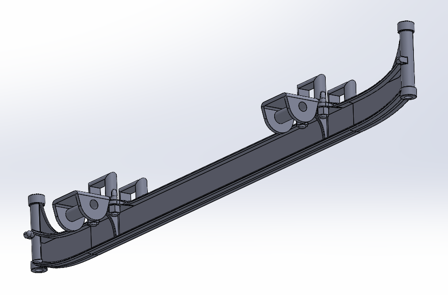
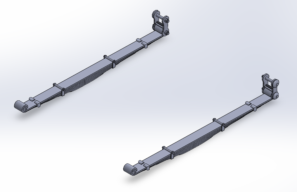
And now the bottom springs are done..... Fun times, And before I go on to the next part, I've got to reconfigure the front springs to better match the rears.... An overall look.... Haven't decided which direction I will go next, but it will be one of the Axles.... Onwards...
-
Well the upper Rear Springs are done.... And the overall... Now to close it out by doing the lowers..... Onwards....
-
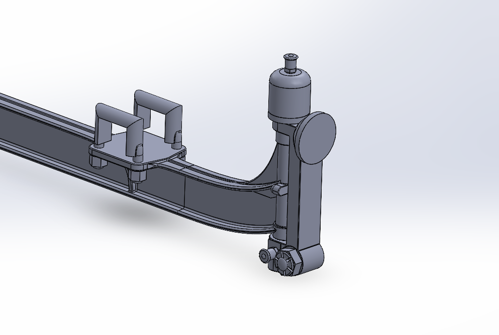
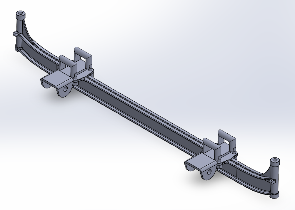
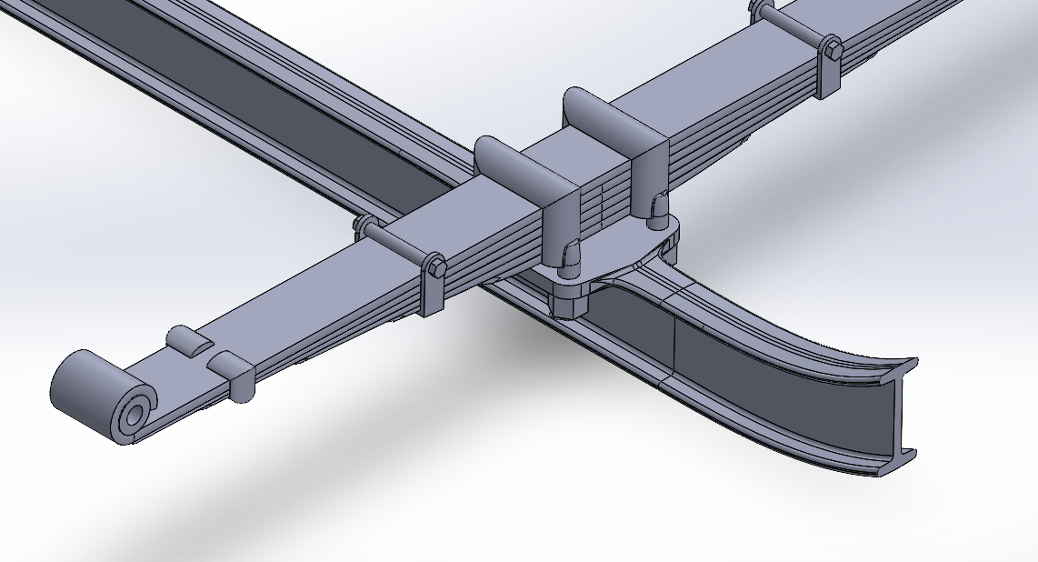
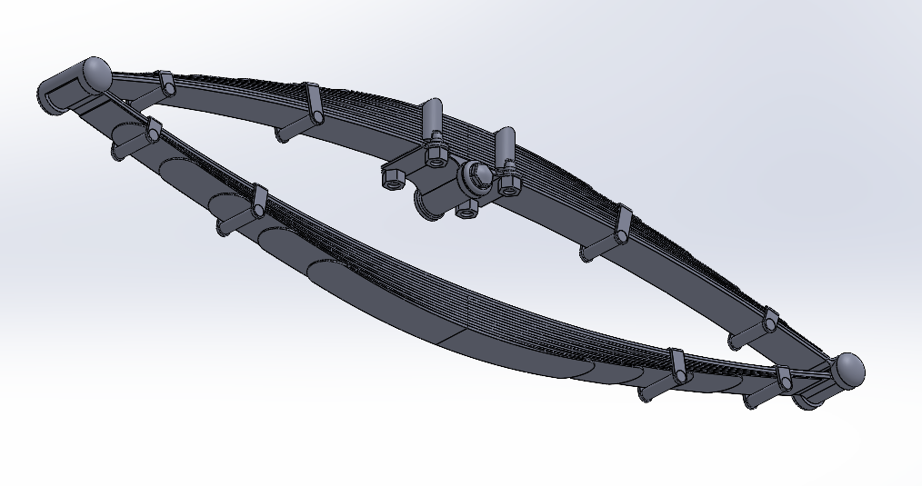
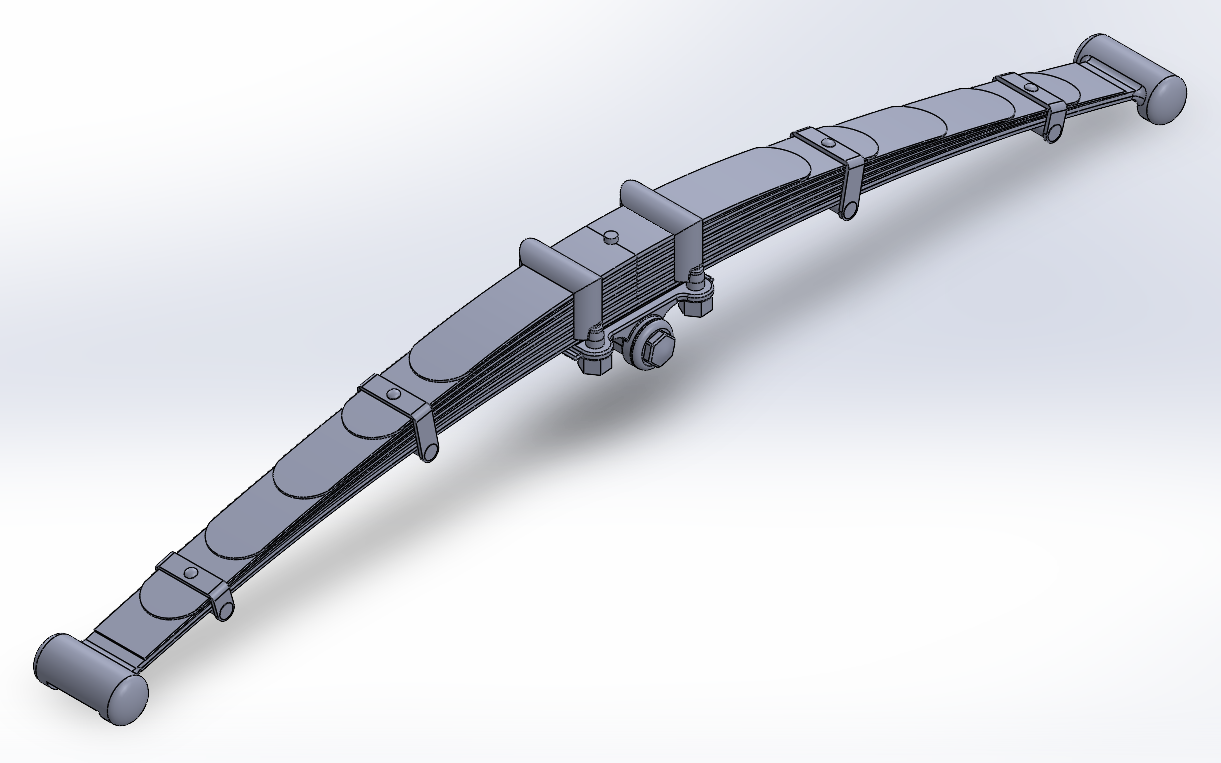
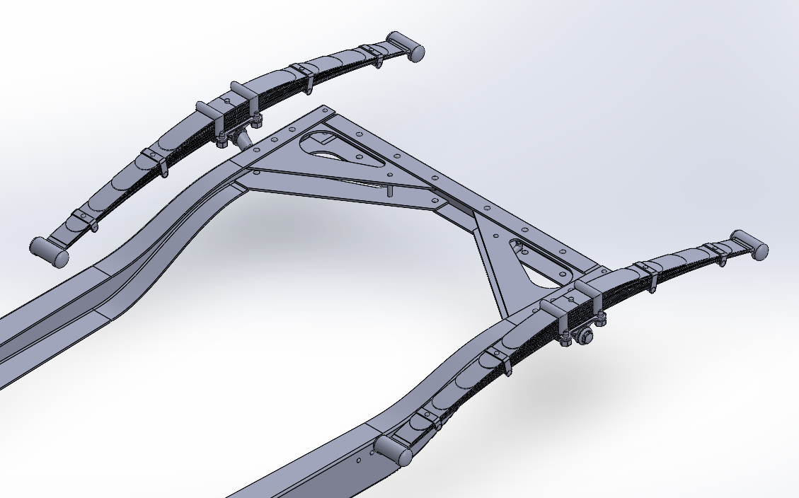
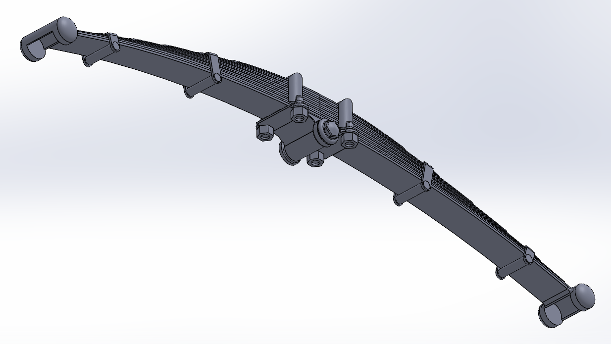
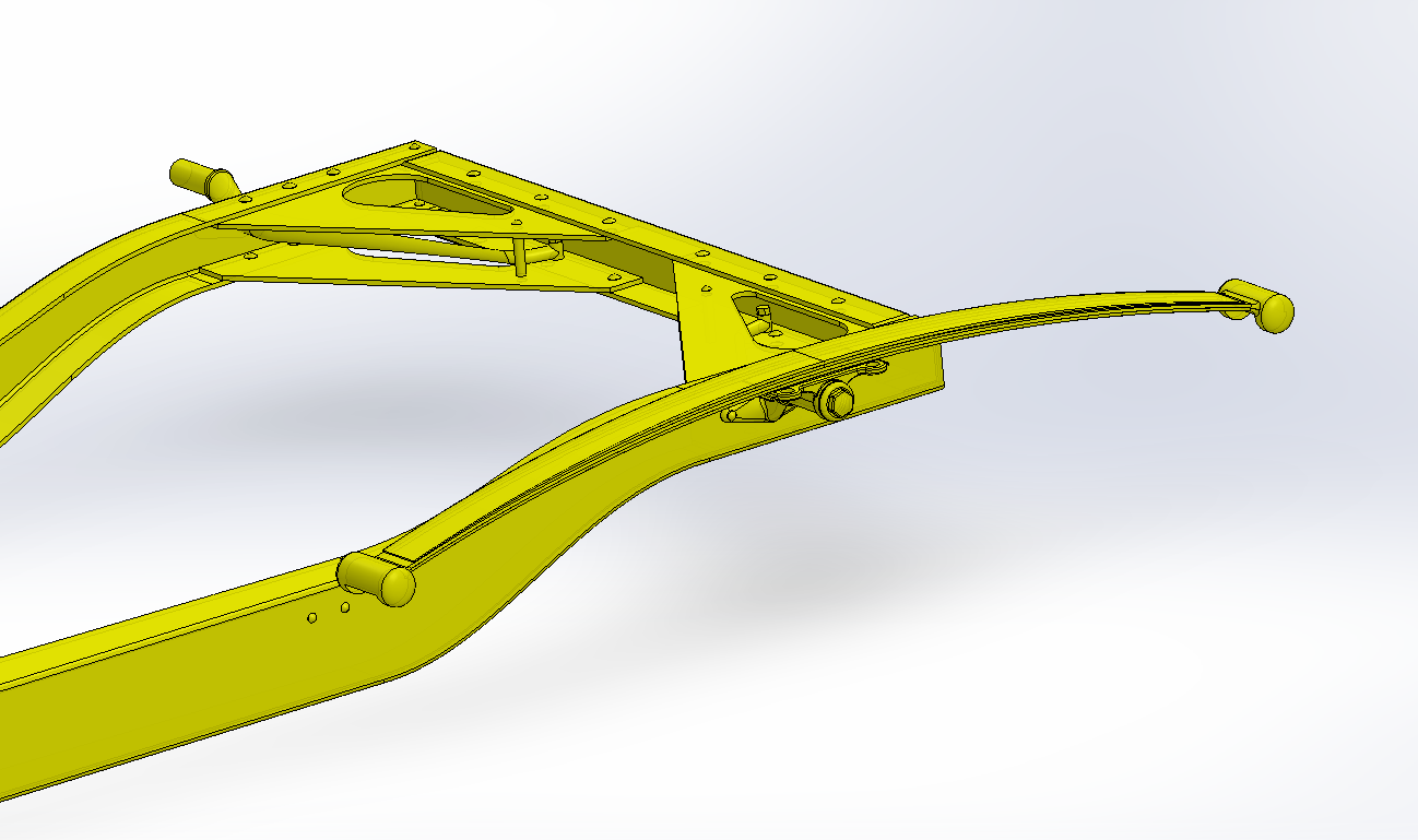
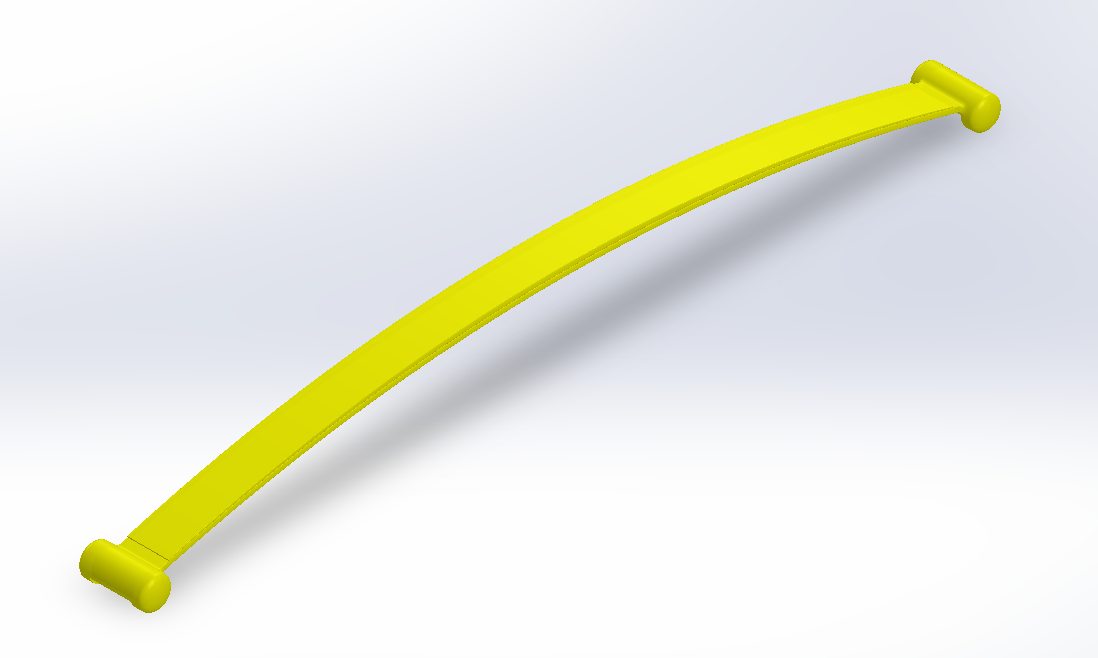
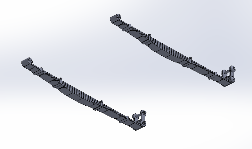
Well another update... Rear Springs, I was hoping that I would be able to use the springs I had already made to build the second version... Unfortunately no That wasn't going to work so I've set about building a whole new set of Rear Springs..... And in measuring it against the detailed photos I now have I found that I also needed to rework the Bracket as well to more accurately reflect it's true position on the car... 3/4ths inch closer to the rear and up at the turn of the curve on the frame rail... Then I added in the old springs and the ends sat way to low, so I was forced to completely rebuild the springs reflecting the correct measured position on the car... The curve is now accurate, 40" long by 2" wide with a 3" drop at each end... I've included two pics showing the current iteration colored in the cars natural yellow color.... And one of the spring itself showing the upper mainspring and first leaf... and it's one solid piece as well.... Next posting when the spring itself is finished... Onwards.....
-
Thank you Ken... Trying to be as accurate to Race Day as possible...
-
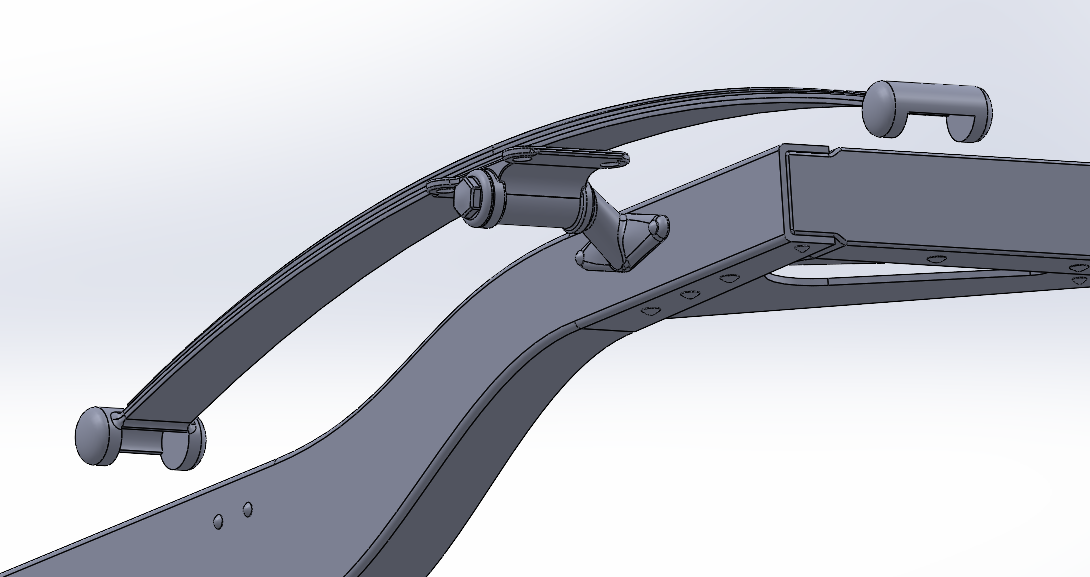
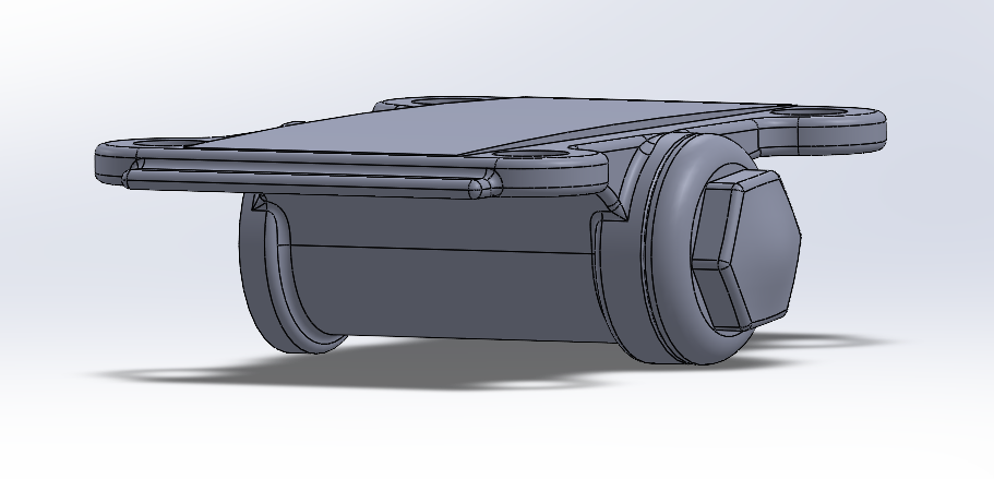
Thanks for the like John It's appreciated.... And I've started the Rear Springs.... First I have to create the mounting plate, it's the pivot point of the upper spring and carries the load from the Wheels & Rear Axle vertically to the frame... Mounting Plate, A lot different than first envisioned.... Thanks to the pics John provided, much, much more accurate.... Reverse side, attached to it's mounting bracket.... And finally in place against the frame..... Now I start to build the upper rear spring.... Onwards....
-
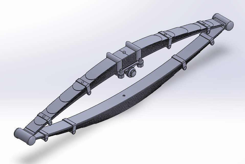
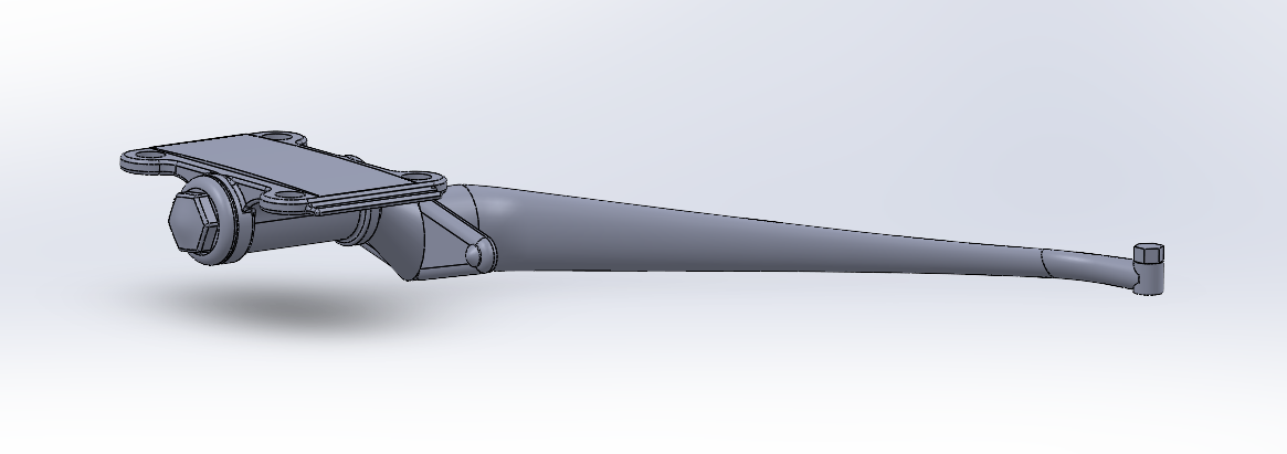
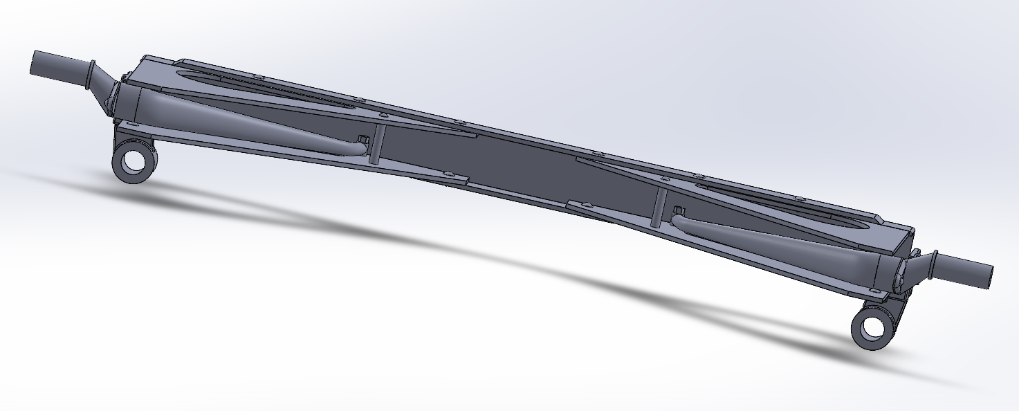
Well another update, this one took a while to create.... Front Springs.... Eight tries at it, five complete redraws..... 2" x 35" Asymmetrical Leaf Springs.... The Axle mount centers 15" from the front pivot point leaving 20" behind the axel The leaves are 1/4" thick at the Axel Mount and taper to 1/16" at the tips and the tips are full width radiused... (my originals weren't) And they are mostly one piece, the two shackles are separate pieces as well as the rear pivot hanger... It wasn't easy... Overall look... I'm going to take a break for a few days, have some RL issues that need to be dealt with, but then after a suitable rest for the brain, I'm going to tackle the rear springs.... Onwards my friends...
-
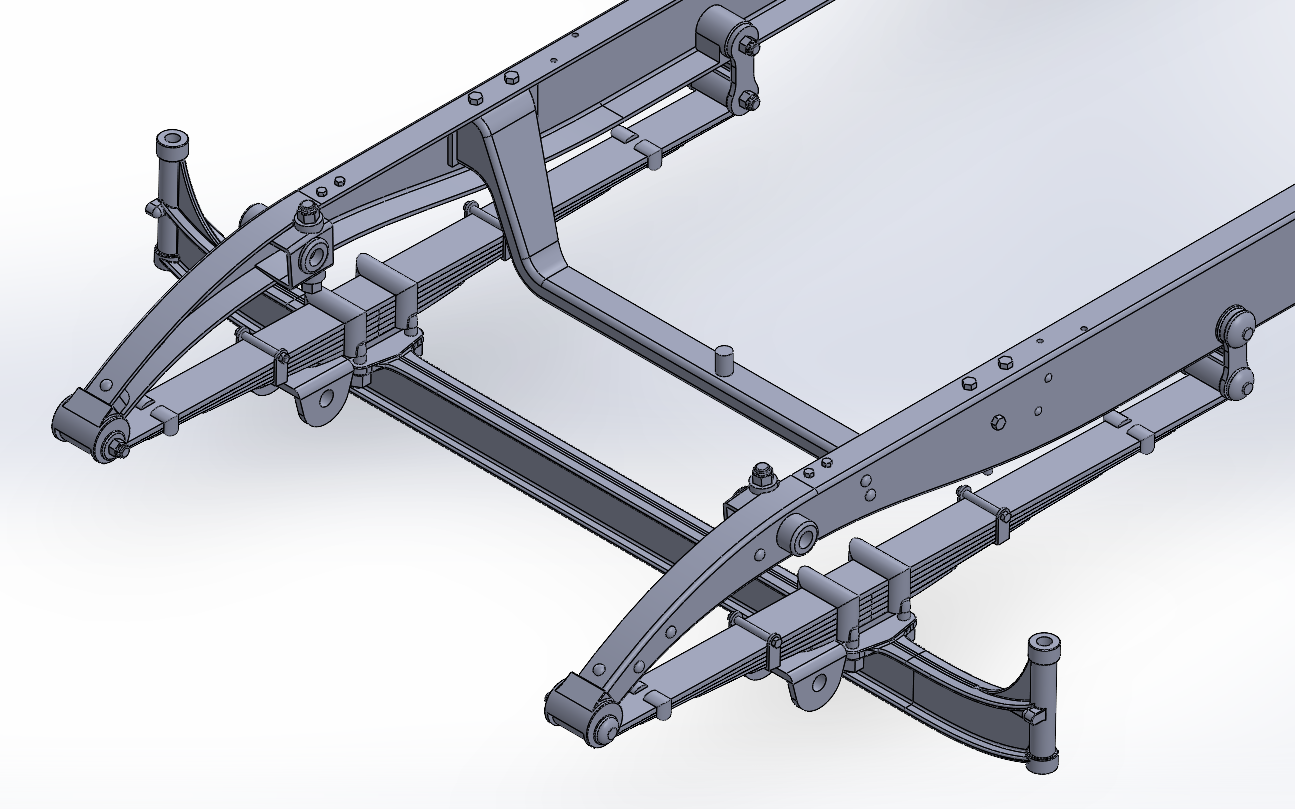
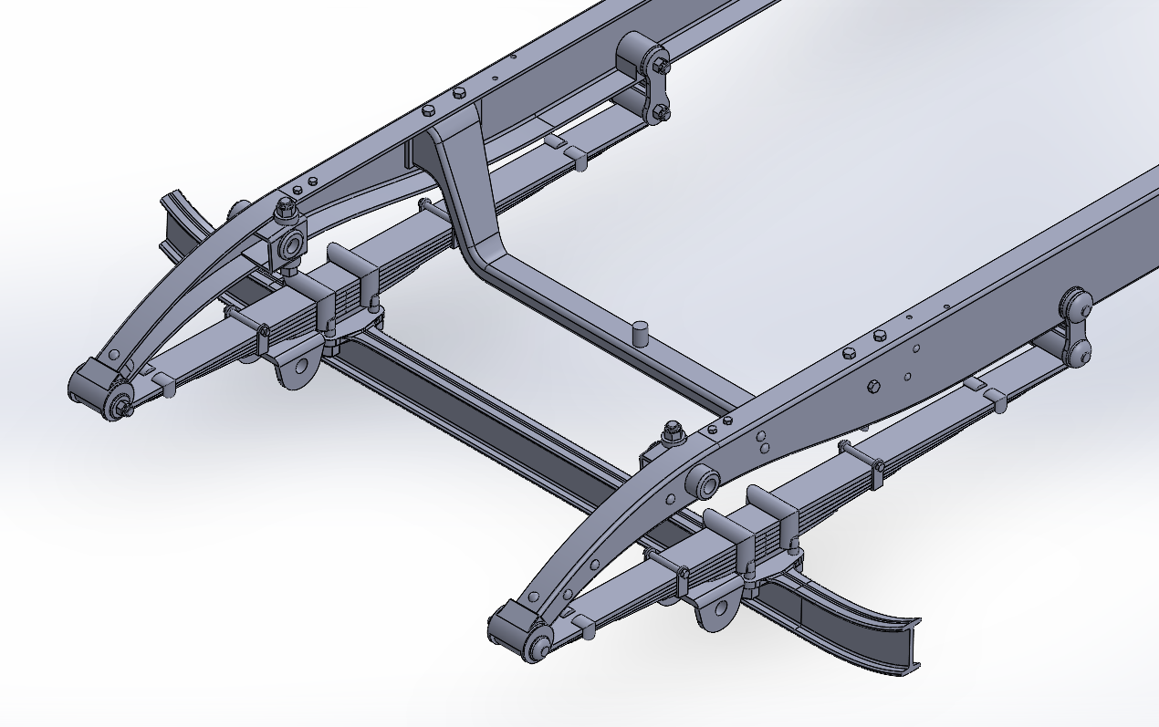
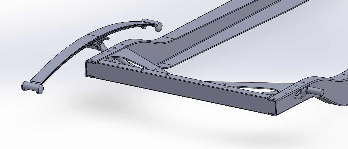
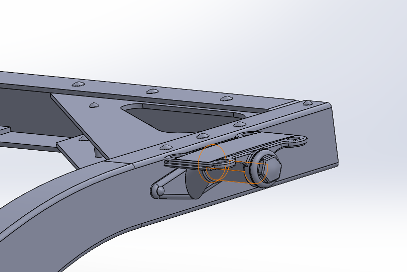
Update: Rear Shock mounts and Spring brackets... (the shock mounts were easy, the spring mount was another story) Overall view of the area... Nothing unusual to the casual view.... Where the spring brackets live.... Different aren't they! not just bolted to the frame... but looking at their actual configuration the mechanics makes sense... And I might add a perfect application of the lever to reinforce the spring pivot point... Out of the frame.... And of course an overall beauty shot... I know, it's only beautiful to us engineering types who like this kind of stuff,..... That's it for today, I'm now on the road to a rolling chassis again... Thanks for your patience with me... EG
-
Thanks John... Your pics really make a difference... Currently done the rear shock mount, it went rather quickly as the original wasn't that far off... The Spring mounting bracket is another creature altogether though... Requires a complete redesign cause my original was way off... Working on it now, next update when it's done....
-
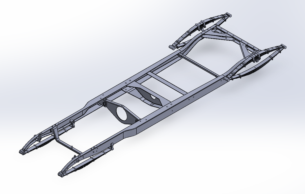
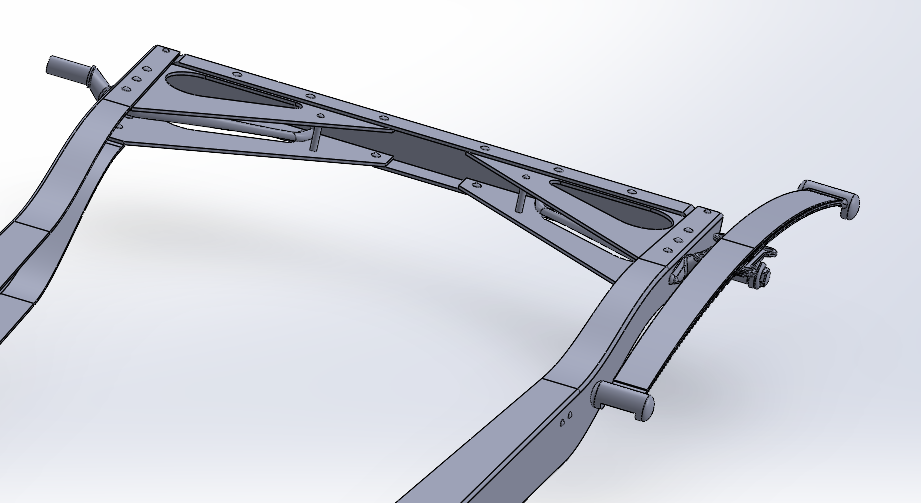
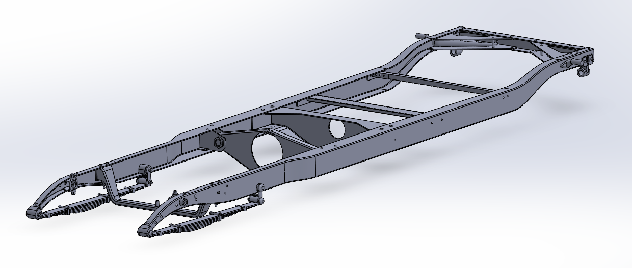
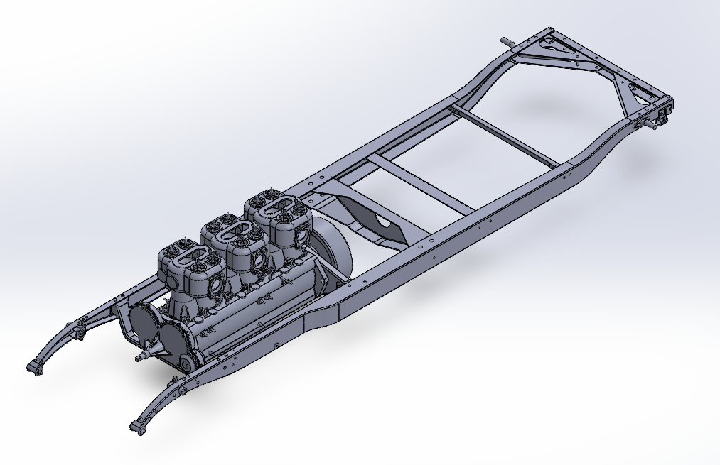
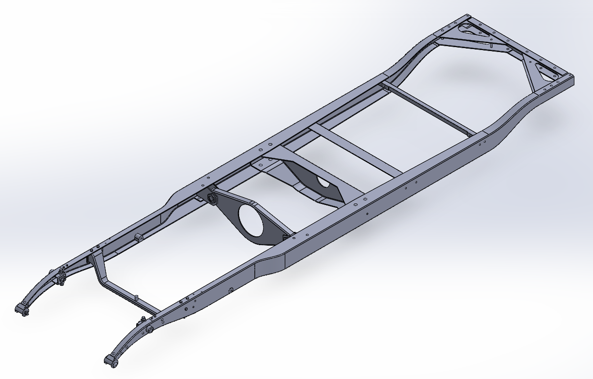
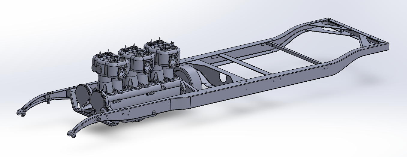
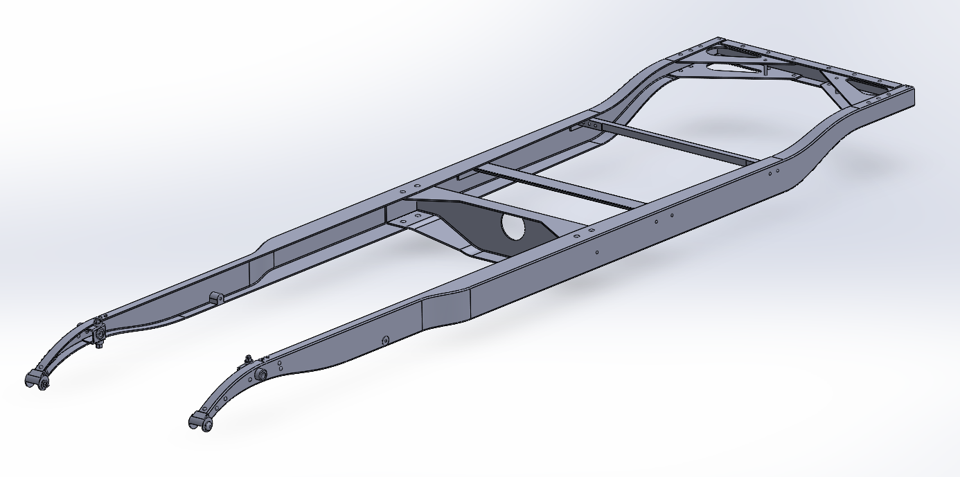
Well another update... Full frame... Except for a few minor details miscellaneous holes bolts & rivets, (added as I add more parts for the most part) she is complete!!! The increased level of detail also includes a bit of narrowing, as I was adding parts on the previous version she started feeling a bit fat so I rechecked and took an inch and a half off her width... Should help with the fitting of parts in the future... I also dropped the engine back into her.... It's the only part that hasn't been adjusted as of yet.. (although I will be adjusting the crankcase flange shortly to correct it's shape) Anyway this is the status as of today, Happy Easter everyone... EG
-
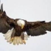
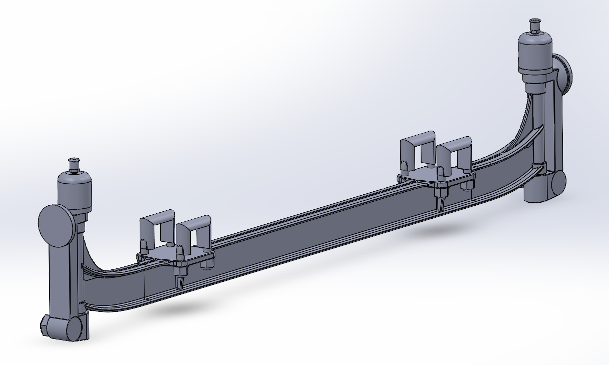
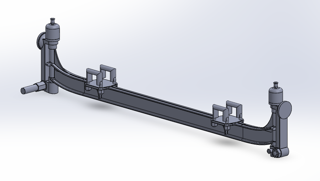
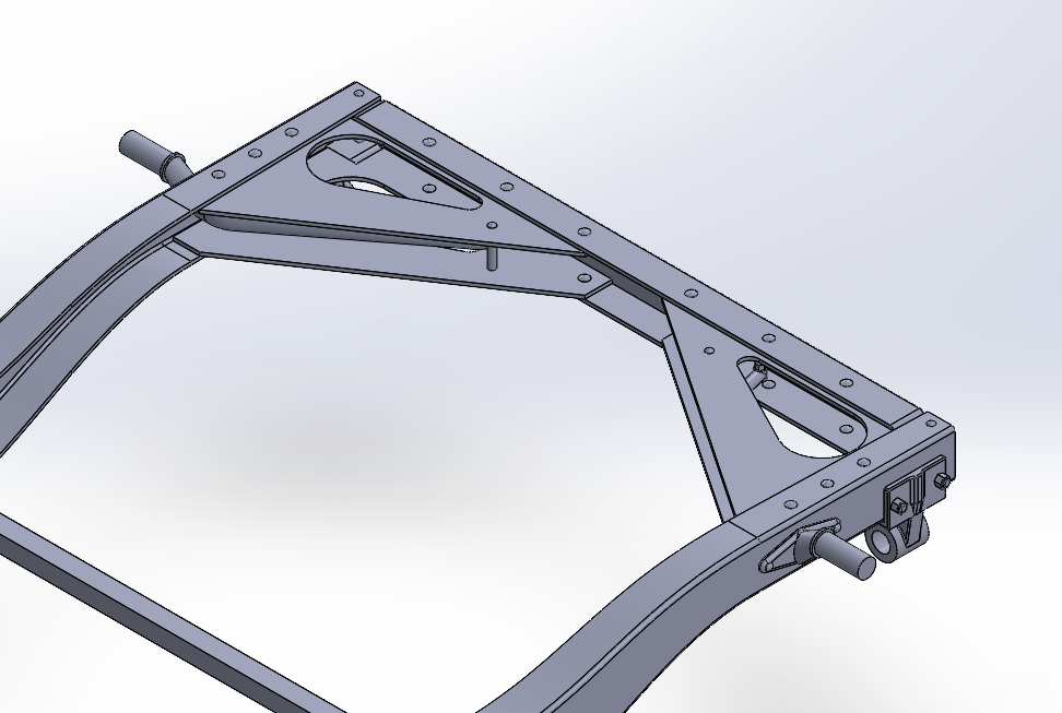
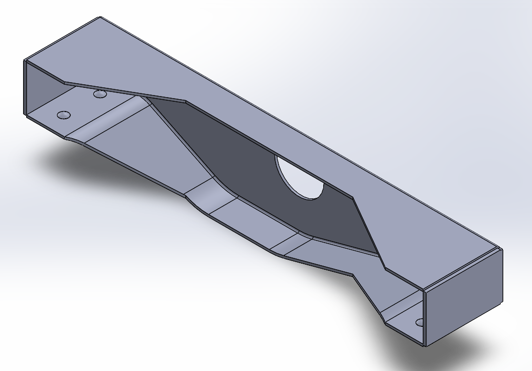
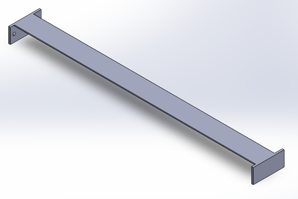
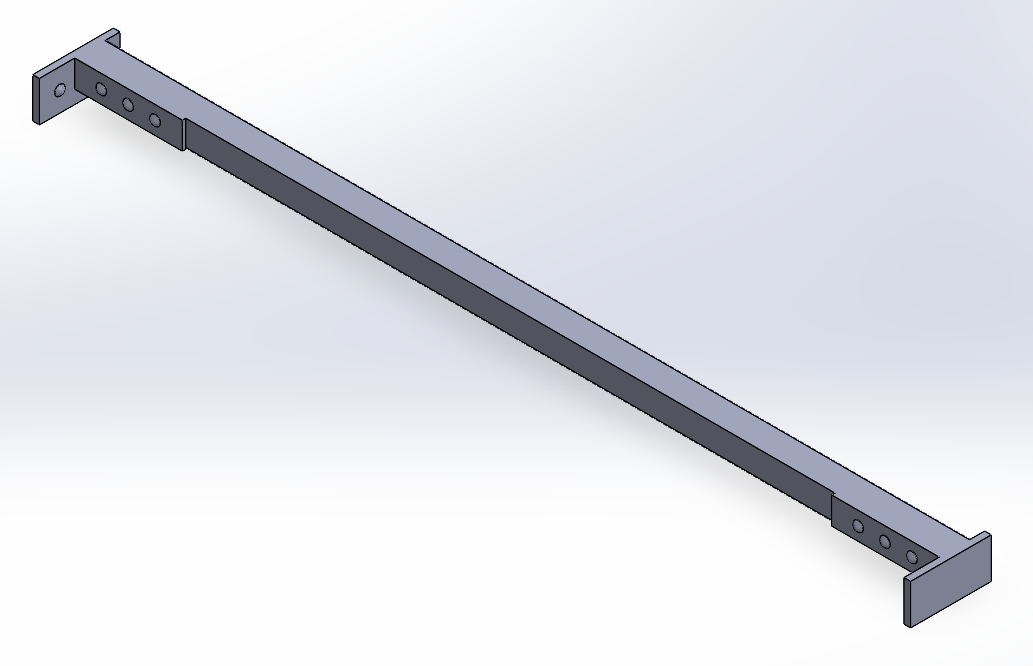
Another update... These would be the Rear Firewall Crossmember, The Brake intermediate shaft cross member and the Center Thrust Crossmember.... The Rear Firewall crossmember, It carries the forward end of the Fuel and oil tanks and the rear wall of the cockpit.... The Brake Intermediate Shaft Crossmember... It carries the levers and torque tubes of the brake system from the left side of the chassis to the right side to actuate the right side brakes simultaneously with the left side... Those two crossmembers are simple angle irons welded to mount plates and riveted to the side frame rails, pretty simple... Finally, we come to the Center Thrust Crossmember.... The Center Thrust Crossmember is the most important cross member as it transfers the push of the driveline to the frame keeping the thrust load of the rear axle & wheels off the springs... It also carries the emergency brake input shaft and the forward end shifter gate which transfers the motions of the shift lever to the shift rods leading back to the transmission... It is made of 3/16th flat steel press formed into a channel and riveted directly to the frame rails... It is the strongest of the six crossmembers making up the frame... An overall view of the Frame where it stands today.... Next up, the rear motor mounts and crossmember.... Onwards....