4knflyin
-
Posts
77 -
Joined
-
Last visited
4knflyin's Achievements
MCM Regular (3/6)
-
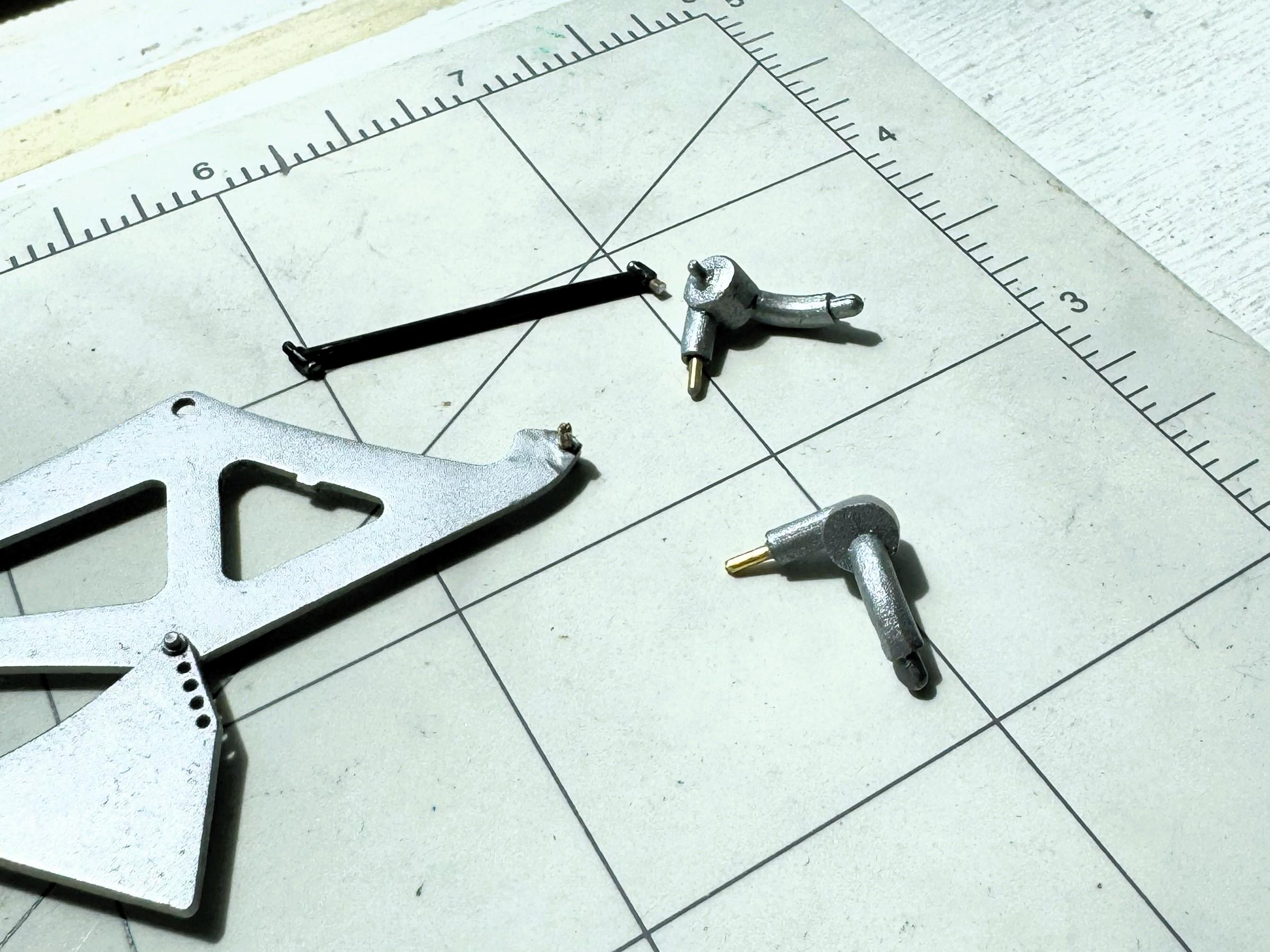
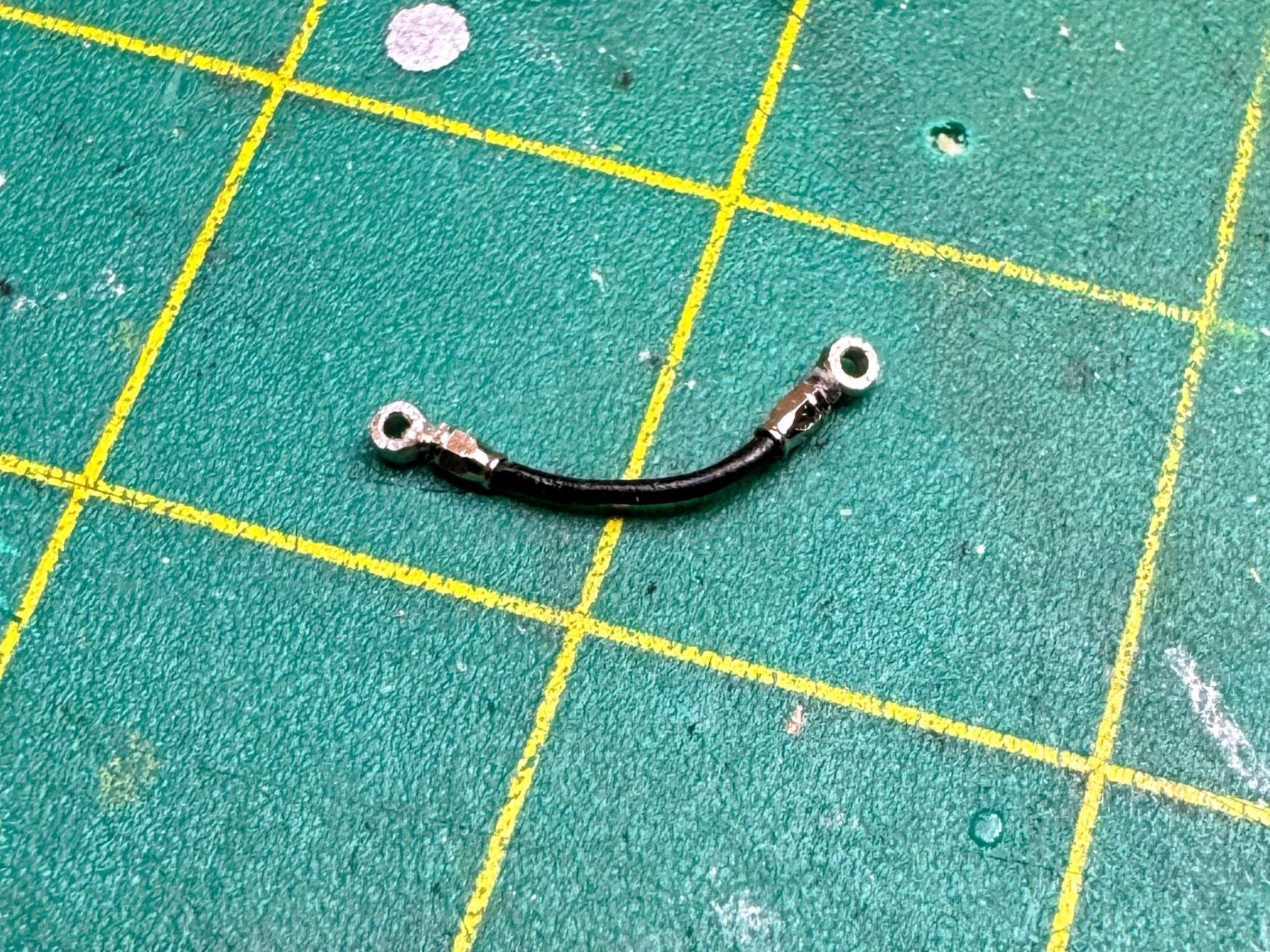
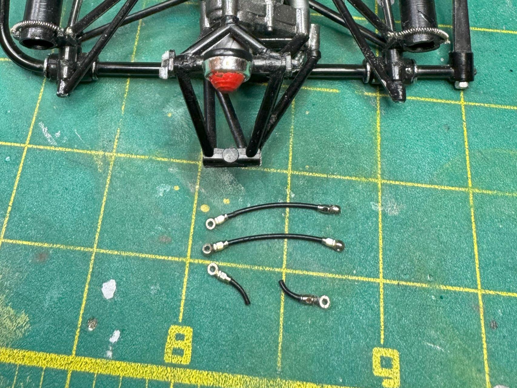
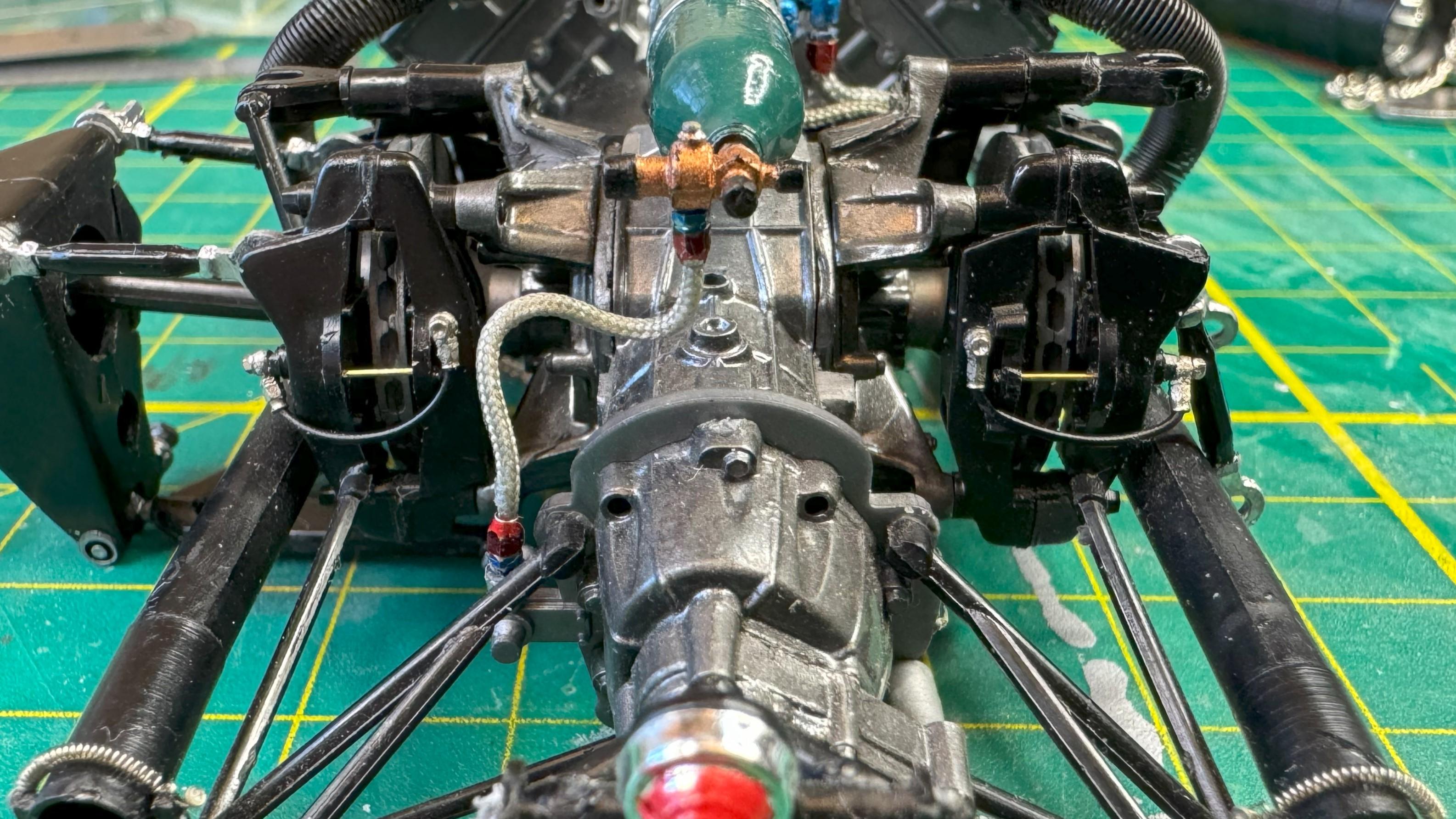
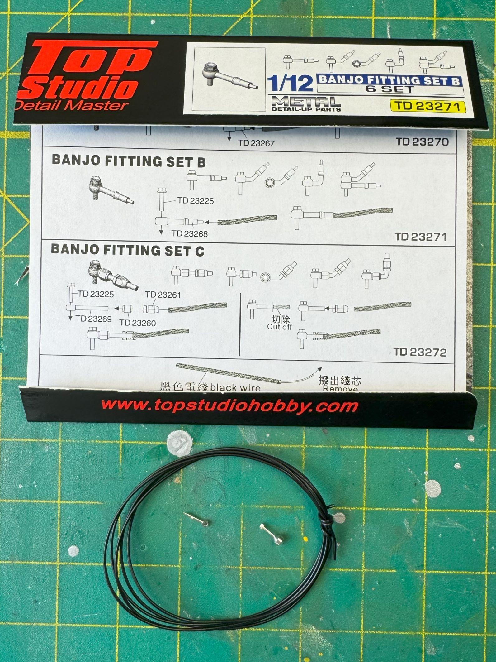
Parts were falling off left and right and I was breaking off others by bad finger placement. Even the motor was a bit loose. I resisted separating it from the chassis for a couple weeks or more, but finally grabbed a screwdriver and started prying. It's plastic... it gave in. The damage the body, both parts and decals, has suffered is stupid. I knew it would suffer. Cripes, you knew it would suffer, and still I went along like there was nothing to see. Until I couldn't stand seeing one more part break off. I should have attempted to separate it as soon as I decided to do more than just add the MFH screen to the kit... a total of six parts. Separate a couple of pipes, disconnect two really long trailing arms, and Bob's your uncle. With my new freedom, I went to work on the brakes. TS banjo fittings type B. John, now I understand why you were insisting on developing your own solution. Although the TS ones work, they are not at all accurate. For one, the banjo bolt head is way off... out there in its own orbit. I don't don't want to go down this rabbit hole... for now. Still, they're better than nothing by a mile. Like I said, type B was the only wrong set for this car: You can just barely see what set 'A' looks like. Very simple. Very appropriate for this project and, as an added plus, the banjo bolt head looks a lot closer to what you'd expect than for B and C. Set C, while too long, at least it's straight. But I have set B. I snipped off all but about 2 mm. The remaining stub was much too thick to fit the wire insulation and hex fitting over it, so I filled each of them down. I put a 1 mm tapered hex fitting on the line I cut, and then simultaneously pushed the brake line and the fitting over the stub. This worked great. When I put the wire on first, after sliding the hex fitting into place there would be a tiny but noticeable bit of the insulation showing. Trimming that caused the parts to separate in one instance; not a chance I wanted to take on every one of them. Plus it's just plain a more elegant process. The halves were my original attempt, which was too short. I don't know if I'll ever figure out a way to attach them to the in-facing part of the calipers, but I'm holding out hope that I'll figure something out, OR, you'll provide me with a suggestion that works for me (hint, hint). Unfortunately I painted them match the reference photo and it didn't turn out all that well. May as well have left them alone. Hope to hear from you.

-
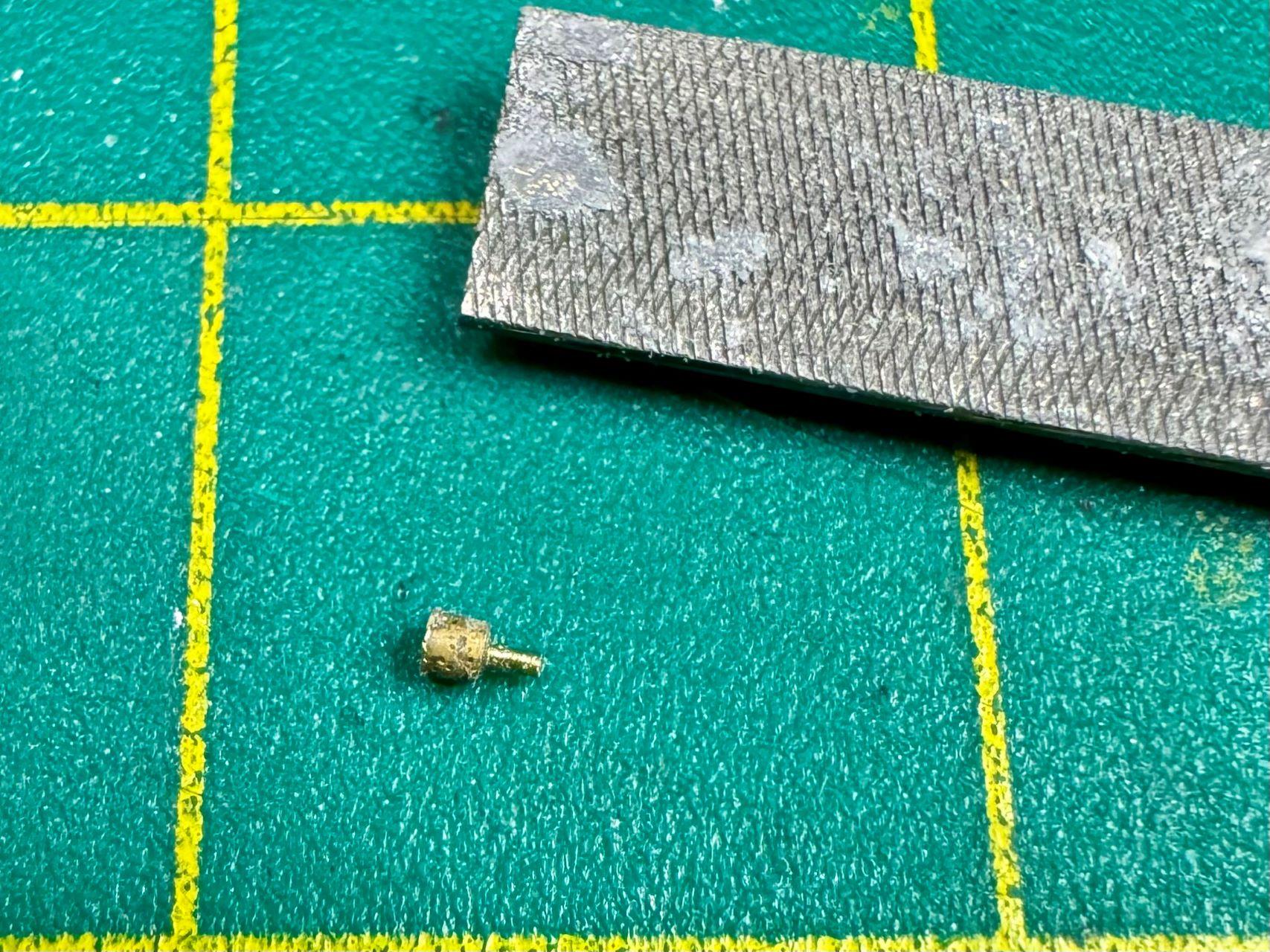
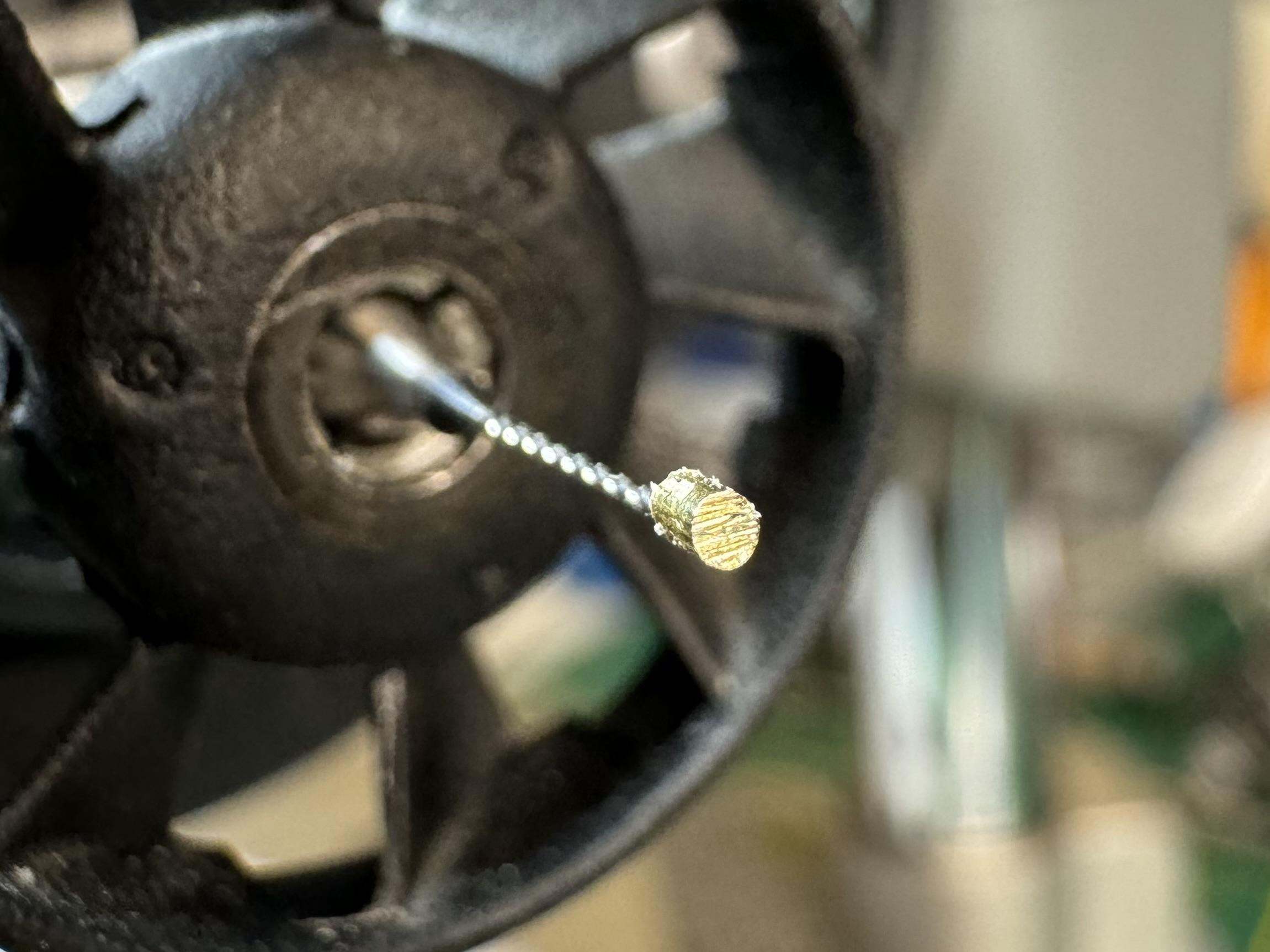
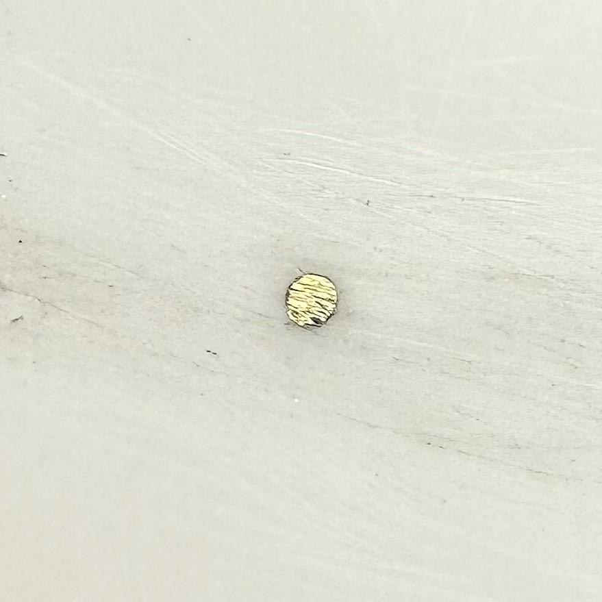
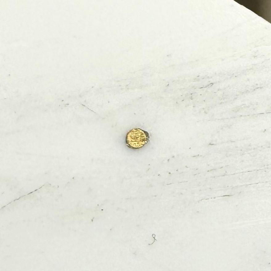
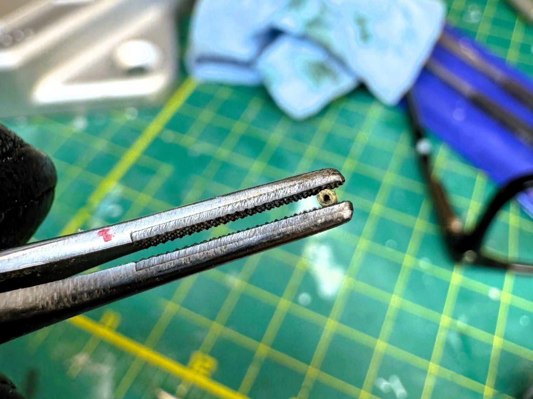
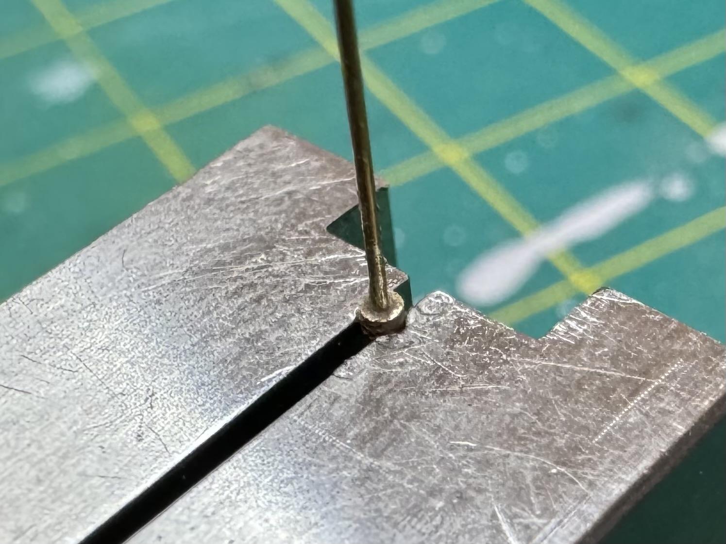
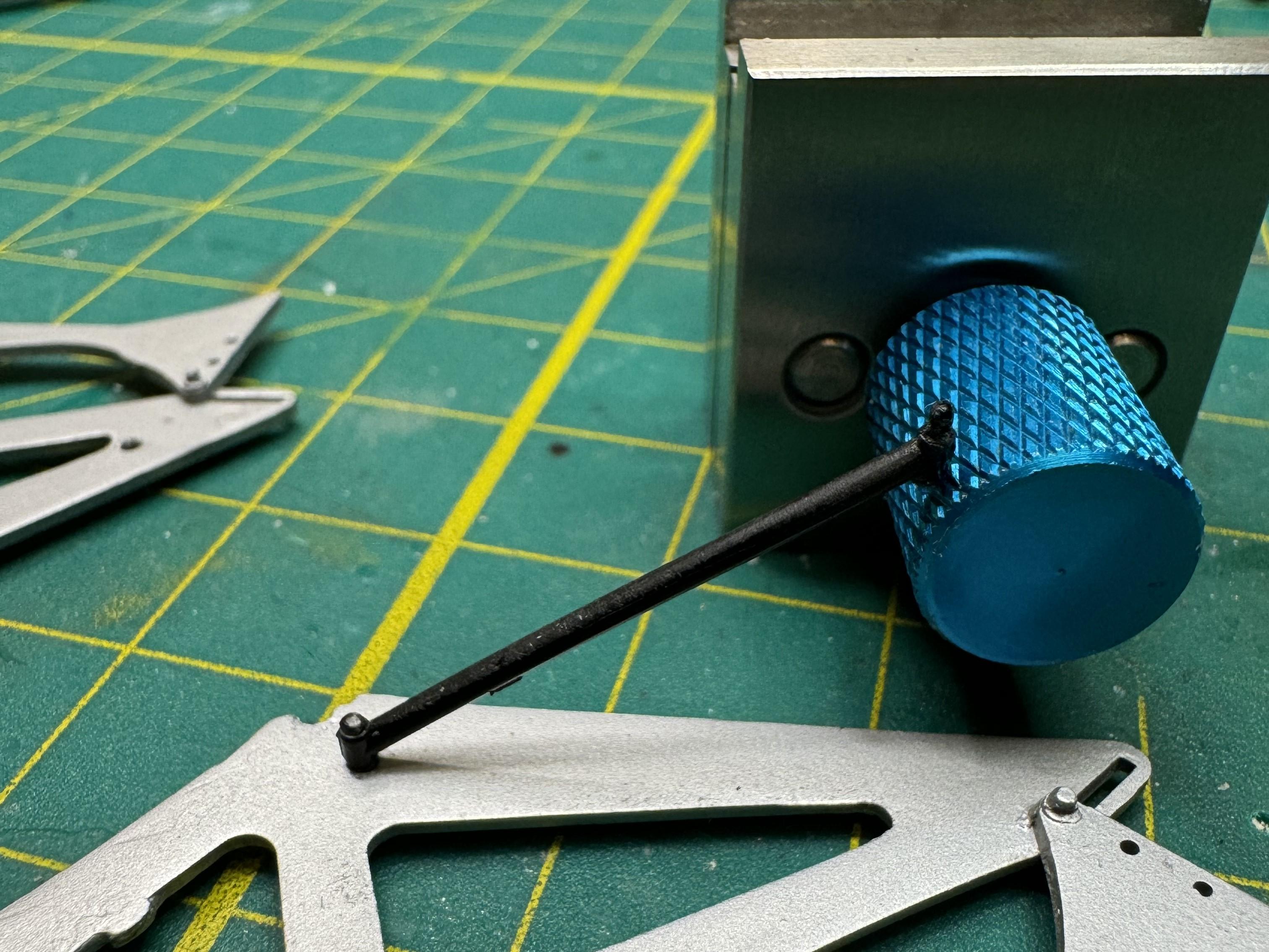
My first save courtesy of my new Dremel drill press ... In excruciating detail. You may want to skip to the next post. I've wanted to be able to do something like this for a long time. It feels good. Only problem is, now I realize I got the wrong tool and what I really want is a mill. What I really, really want is a mill and lathe. I've wanted to learn machining for a long, long, very long time. Honestly, probably starting in my early teens. That and welding. Edit: If at any point you say to yourself, "I would have...," or, "he could have just...," or words to that effect, pray tell. It's not only appropriate, from my perspective, it's desired. I would love to know the alternative you would have used. It may be my preferred alternative going forward! Anyway, more stuff has broken and/or come of the model than I intended. A very incomplete pic of repaired damage so far: Learning to make repairs that actually cover the damage instead of just suffice to keep me going was one of my few stated goals upon returning to the hobby. I'm happy to say I established my seriousness toward achieving it while working on the B192 (it's resting, so much damage, honestly). As for the repair made possible by the drill press: A locater pin (or whatever they're called) broke off a delicate crossmember part of the rear wing support. The hole in went into is 1.0 mm dia. I think the pin measured 0.8. The problem with what otherwise is an easy fix is that where the pin was located is hardly bigger around than the pin itself. I didn't trust myself drilling out such a thin-walled hole to insert some brass. I needed the hole to be a whole lot smaller than the surrounding plastic. My idea was to drill a small hole, say 0.3. mm, to fit an anchor for a bigger piece that would be attached to it and serve as the pin. But how to attach the pin and anchor? I decided drilling a hole in the center of the pin was the way to go (telescoping sized brass pipes would have been a better way to go, but alas...). But the pin had to have a diameter no bigger than 1 mm across. I couldn't drill that by hand without a whole lot of time and a whole lot of swearing. Time for Amazon. When the drill press arrived, I went right to work. I drilled a 0.9 hole in 1 mm styrene and inserted a 1 mm dia plug. I filed both sides flat 1) so that the styrene substrate could be placed over a solid area to provide the resistance I needed to drill, and 2) the hole the part fits into is 1 mm deep, so I won't have to do any more sizing in that respect. Bottom (I think. Hmm.): So I set it up and started drilling. Never letting up to release some heat (and save the bit), it finally melted its surroundings and came off stuck to the bit. (The distortion sure make that look longer than 1 mm, doesn't it?) Notice that the drill bit is a "bit on a stick," and as we all know, they are very brittle. Gently unscrewing the part was not gentle enough and that bit is now toast. I did it again, but this time, at the end, I heated the plug before twisting... success! Man, I had know idea brass heats up so fast. It was red-hot a couple seconds after putting it over my lighter. I should add that I didn't heed my own advice on the second go and melted the plastic again. I need to get some hardwood and also be kinder to my bits. I also need to get better acquainted with the materials we use, in this case brass, to aid us. I don't know how many times I attempted to CA stainless steel to make a part before I googled it. Back to the drill press. Well, it worked: My jaw dropped when I saw how the previously virtually impossible was now possible. And the piece of 0.3 mm stock fit quite snugly: Curiously enough, despite the hole in the crossmember being dead-on center as is the brass, it fits weird. It actually wobbles when turned. But all that matters is that it will do the job and I learned a new trick. That's all folks... for now.
-
Trumpeter Ford GT40 with my twists
4knflyin replied to kensar's topic in WIP: Other Racing: Road Racing, Land Speed Racers
This is turning out to be a uniquely interesting thead. All the additional pics, diagrams, sources for parts. Mixed with your descriptions when you provide them, this has the markings of entertainment and info gathering for many months to come. Thanks! ANZY looks like an interesting source. I'm going to have to check them our. As for the old Detail Master, I thought the core was removeable... good to know I'm wrong if I ever come across some. I've been using Top Studio and DecalCas braided lines (I have some Tamiya, but I don't like the way they look). I'm not sure about the colors, but the lines are realistic looking. People rave about ProTech braided lines for American motors. Actually, just in general. I haven't bought any from them because they aren't scale to metric, which makes them an odd fit for the AN fittings I use, but I am going to give them a try. When referenced, it's usually with a comment like, "Wow, I'm never using another brand again." So on and so forth. They can't all be blowing smoke. The link is https://protechmodelparts.com/. Keep it coming. And thanks. -
Trumpeter Ford GT40 with my twists
4knflyin replied to kensar's topic in WIP: Other Racing: Road Racing, Land Speed Racers
These are great references. I sure hope you glom onto my first start to finish build 😘 -
Trumpeter Ford GT40 with my twists
4knflyin replied to kensar's topic in WIP: Other Racing: Road Racing, Land Speed Racers
Seems I found this at an opportune time for me. Definitely following. A couple questions. I just threw away a couple bills on a Dremel w/ drill press. After using it a couple times, it occured to me what I may really want is a lathe. Do you have a thread on yours? (Edit: I finally saw a post with yours. I was thinking table-top lathe with hand tools. Still, if you have some relevant pointers or links, I would greatly appreciate it.) Or would you point me in the right direction. Welding and metal lathing have, literally, fascinated me since I was a little, tiny kid and I think I need one. The other qu. is about the Meng bolts. Almost pulled the trigger a month or so ago but I was thrown by the way they mix the sizes and, especially, the means by which one has to separate them from their substrate. I'm guessing doing whatever you are to separate them is not bothering you, yes? And, no, you can't beat that price... if you want to paint nuts, bolt heads, etc. Thanks. I'll try to keep the interruptions to a minimum. This is great so far. Thanks for posting. -
Thanks for chipping and chiming in. Before I remembered how to do it in a reliable, and repeatable way, that doesn't even take very long, I thought of ramming a SS rod in there. I chose stainless gambling that it would be the least noticeable. Then I realized I'd have to do that before I modified the spring and I didn't want to risk the few springs remaining that I had. But knowing that you did it means it woun'b be a gamble me me if there's a next timer with this problem. Your 917 is great. Know how I know that? I was an earlier follower of that thread. Everything so clean. Oh god, I can't even do that with my microscopic (1/:2) Cessna 150 test subject. I'm serious about the 917. Everything is so tight, like all the other guys' work in this forum. Bottom line: I'm enjoying myself. I appreciate that you took the time to respond with helpful comments and suggestions. Come to think of it, maybe black is a better idea, especially if it's matt. Keep the shiny side up.
- 24 replies
-
- 1
-

-
- lotus 78
- mfh detail kit
- (and 2 more)
-
Ferrari F 2003 GA
4knflyin replied to Chris Smith's topic in WIP: Other Racing: Road Racing, Land Speed Racers
Okay, now you guys have to take and post pics. No! Definitely not selfies. THE GTO. -
Re: the former: I get it about commenting. I'd ask you to make an exception in my case. I need the critical input. I got more from your Mk. III thread than you wrote or pictured. One is that many of you have been doing this at an advanced level for decades. It told me a lot about why your master cylinders and brake lines on the MS-11, pretty much all that you completed on the forward bulkhead, had me looking multiple times before I could declare they're 1:12, not 1:1. Truth. Not being too kind :). I don't want to take months or years to learn something where somebody could have, accepting the risk of "offending me," or maybe because of that :), corrected me in a singe post. Re: the latter: Yes. Getting bogged down into a state of paralysis is not unfamiliar to me. I had that MS-11 model only a few years after it came out. I never started it because I knew I couldn't live up to my expectations. In this case, if you look at the 2nd spring from the left, the upper mount, it is with the spring end bent so that it divides the spring diagonally perfectly. And now I remember how I did it and it's easily repeated. And I have four serviceable springs remaining. Back to the former: they stay as is... all wavy as two of them are. If for no other reason than to demonstrate a lesson learned. Thank you!
-
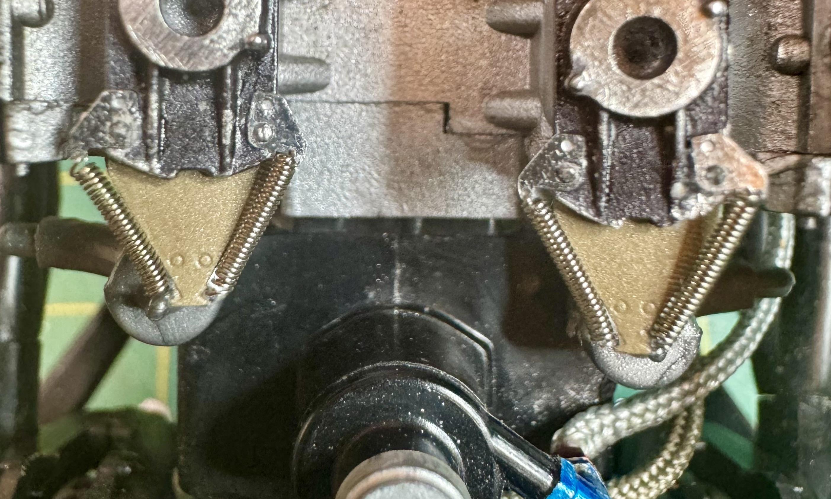
Would you accept this in your own work? This is an honest and serious question, as I frequently wonder if I’m sweating certain details, details that are holding me back. Please do not take into consideration my limitations, and focus only on what you would do with this product. As I predicted, the ears and springs came off the one completed throttle body due to mishandling, so last night I had to attach all four springs. In addition, I added the goal: reduce/eliminate the uncoiled portion of the spring ends. What you see what you see that bothers me is springs that are no longer straight because they were slightly too long or needed to be twisted to them hooked (once you turn one to the point that the hole is into the coil part, the spring gets wonky). On one of them, you can see that I attached it from above on one end, and from below on the other, which isn’t the greatest look, either. Reducing the amount of uncoiled spring required first stretching them so the coiled portion was 6 mm in length. The second step was to cut off the loops and bend the coil ends so that they were in the center of the coil radially. (Think of a circle with a diameter line.) This turned out to be the most fraught part of my process. The problem was that, because you’re bending it to a 90° angle perpendicular to the spring, it’s can’t help but end up resting against the part of the coil that is 180° from the 90° bend, if you follow me. This made it impossible to get the spring into the loop. And, incredibly frustratingly and time consuming, trying to bend that diameter line such that there is a gap between its end and the coil can only be accomplished, by me at least, with luck. An alternate solution, and one that I would have preferred, would be to cut that diameter line such that it was shorter than the full diameter of the spring. That would’ve been the best solution if I could make that cut. But I couldn’t. None of my myriad nippers could get in there and do that. Thank you for your frankness. I’m going to hold off installing them for a bit, hoping to get at least a couple of responses before I do. So, please, do respond, if only with a single word.
-
Ferrari F 2003 GA
4knflyin replied to Chris Smith's topic in WIP: Other Racing: Road Racing, Land Speed Racers
Ahh, the (in-blown) diffuser. I love the way they look in general, and that one is a beaut. -
Ferrari F 2003 GA
4knflyin replied to Chris Smith's topic in WIP: Other Racing: Road Racing, Land Speed Racers
Ditto. You guys both inspire me and, if I allow it, make me jealous. I could have fit in some model building throughout the decades had I the patience to let them be long-term projects. Qu: What is the — I’m assuming to be protective — material visible in the cockpit photos, and what specifically is its purpose. What is it protecting, if that’s it? -
I meant to add an edit after I looked it up. If somebody had said a “gemstone tumbler” or something similar, I would have known exactly what they were talking about. “Magnetic tumbler“ is not what it was ever called when used in discussions that I’ve been party to. I’m glad to know the correct name. i’m learning things I didn’t even know I came here to learn! It’s great.
- 24 replies
-
- 1
-
-
- lotus 78
- mfh detail kit
- (and 2 more)
-
1973 Porsche 917/10 Can Am
4knflyin replied to Scale-Master's topic in WIP: Other Racing: Road Racing, Land Speed Racers
This build has been a treat. I eagerly await seeing her up on all floors. The contrast and, oddly enough, similarities between this and T-70 build are fun to consider. -
BLAH_BLAH_BLAH_BLAH, they are the carburetor... they're throttle plates. I won't go into detail, but I've spent a lot of time maintaining my track car, and the throttle has been off the manifold more times that I can remember. Of course it's the throttle. I mean, that thing is called a Throttle Plate if memory serves me. Thanks for that! Also, that MFH steering wheel on your F2003 is an abomination. Somebody has got to provide an aftermarket one where knobs look like knobs, not blobs. Don't cement it on! Wait for the detail kit or 3D code to print one. You know somebody with a printer is going to tackle it. Edit: "BLAH_BLAH..." Where did that come from. Is "BLAH_BLAH_BLAH_BLAH" a bad word? (I think I said, "Holy BLAH_BLAH_BLAH_BLAH.")
.jpeg.580d21edfef7a22edb9593cd10411e6b.jpeg)
.jpeg.544f7c26deb92c4041bb71f9b2fe402c.jpeg)
.jpeg.6c90381abc69e47a378f5e06d4d65680.jpeg)