Ferrarifan
-
Posts
39 -
Joined
-
Last visited
2 Followers

Ferrarifan's Achievements
MCM Regular (3/6)
-
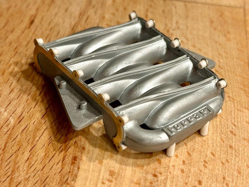
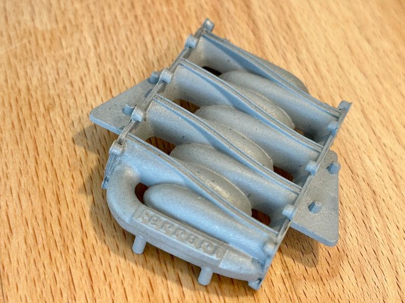
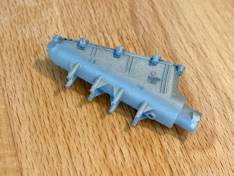
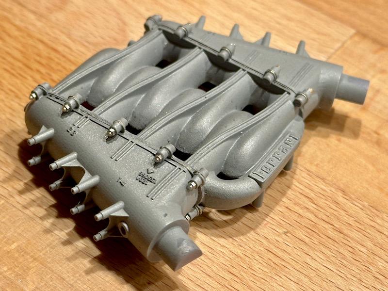
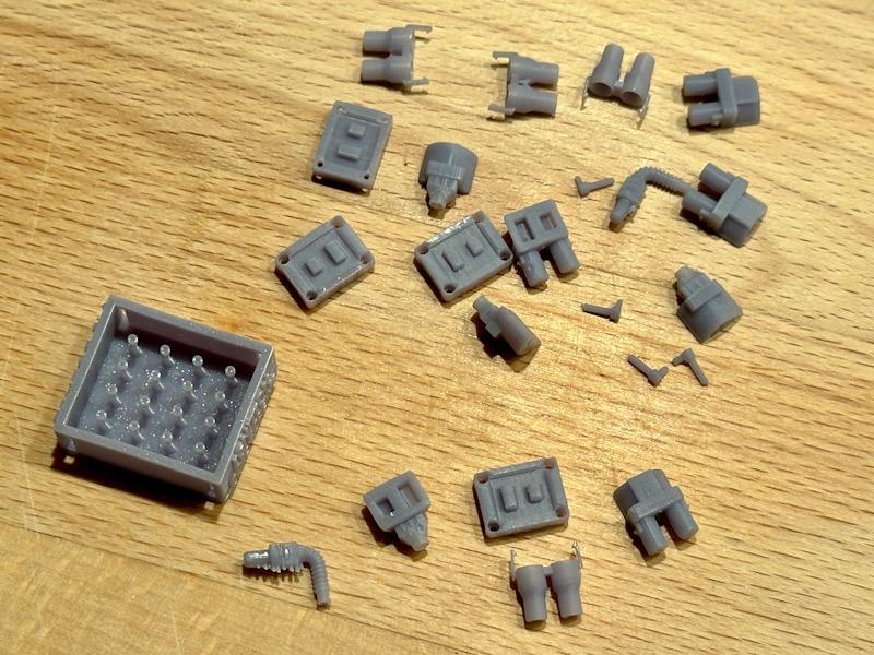
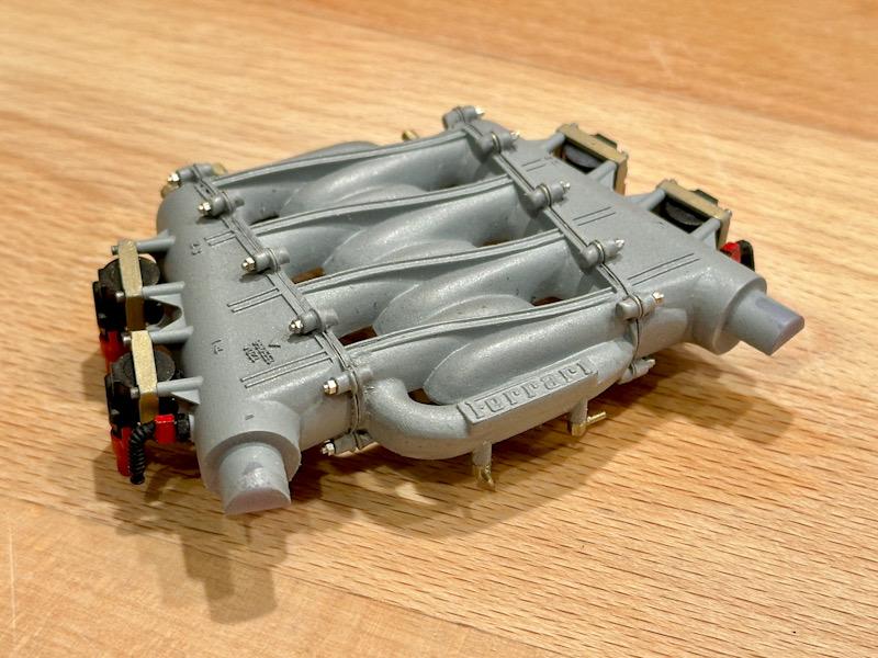
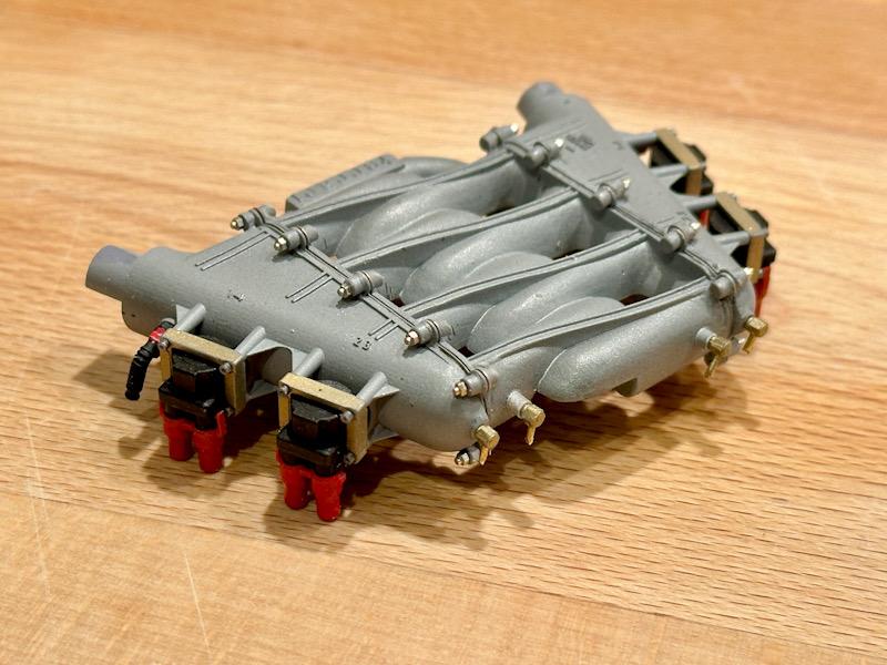
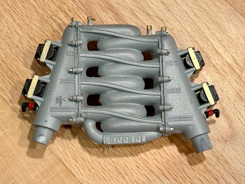
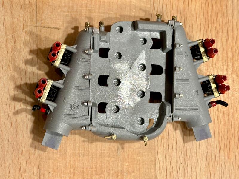
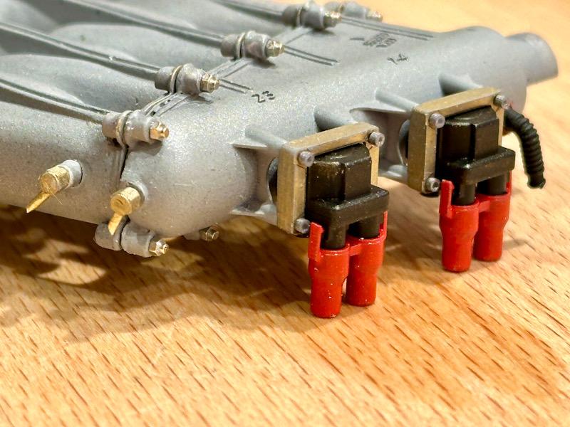
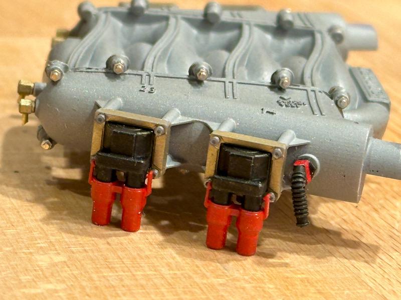
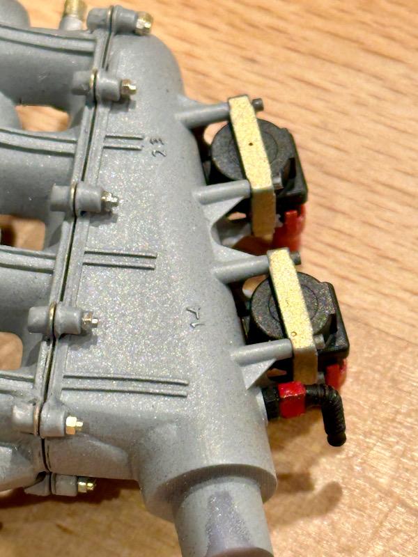
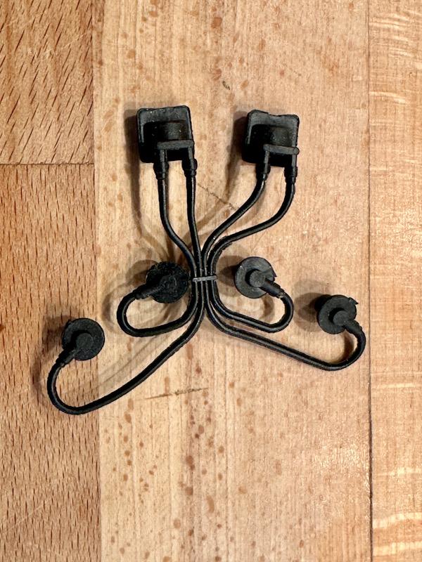
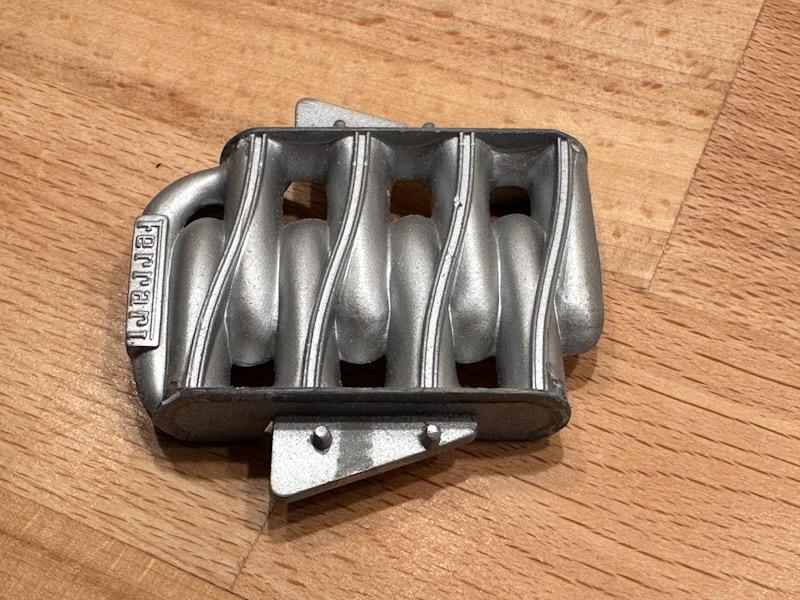
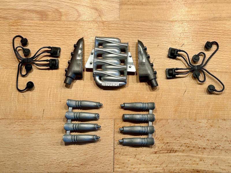
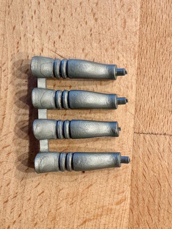
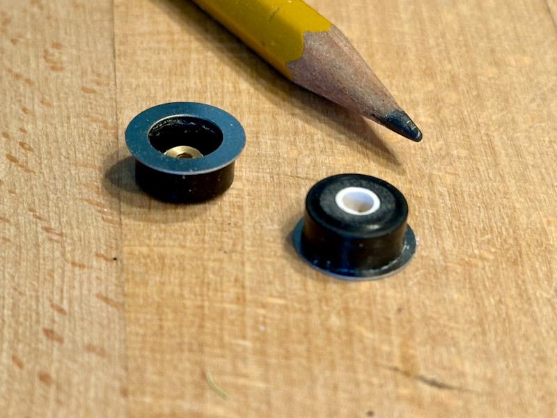
Today, the work continues with the intake system. Here’s the starting point of the upper intake manifold: The Autograph transkit includes etched parts for the flange connecting to the side intake ducts. Once these were glued in place, the bolts for the mounting were also added. Afterward, the part was primed and painted. The side intake ducts from Pocher lack many details. The ribs and mounting domes for the ignition coils, for example, are completely missing. In the meantime, Leadfood Models has released a fantastic transkit that includes highly detailed intake ducts. The quality is outstanding! Even the raised lettering matches the original down to the smallest detail. The only modification I made here was adjusting the flange to fit the intake manifold. I also used the etched parts from Autograph and added the mounting bolts here as well. Afterward, everything was painted. After painting, the parts were glued together. For the bolts, I used micro-studs made of copper. Since these are made of brass, I recolored them to steel using AK Interactive’s True Metal paste. In the Pocher kit, the ignition coils are made of rubber and also include the ignition wires and spark plug boots. In contrast, the ignition coils from Leadfood Models are highly detailed. In addition to the ignition coils, there are also plugs for sensors. The print quality and fit of the parts are the best I have seen so far! A big advantage is that they consist of several individual parts, making them easy to paint cleanly. Another special feature is that the parts can be glued together perfectly thanks to printed positioning aids. Subsequently, the ignition coils and sensor plugs were attached to the intake system. Here are a few close-up shots: That’s it for today. See you soon, Your Ferrarifan

-
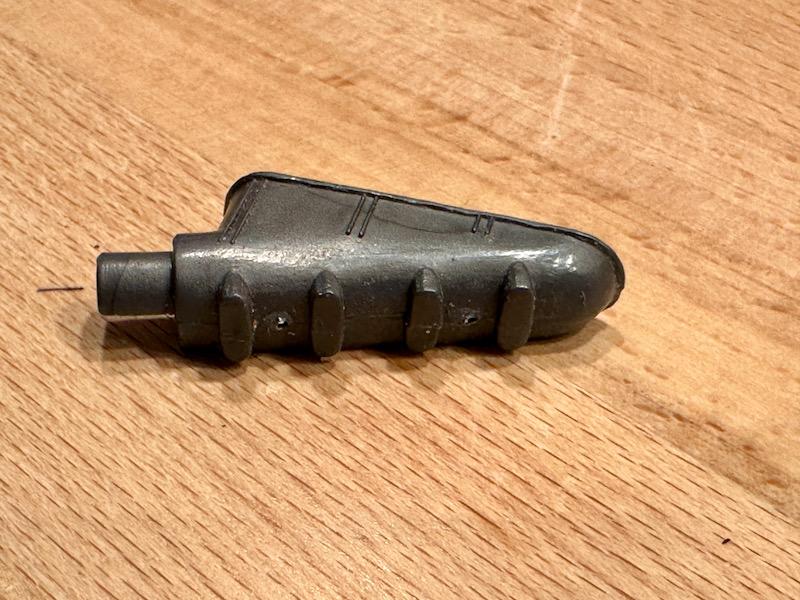
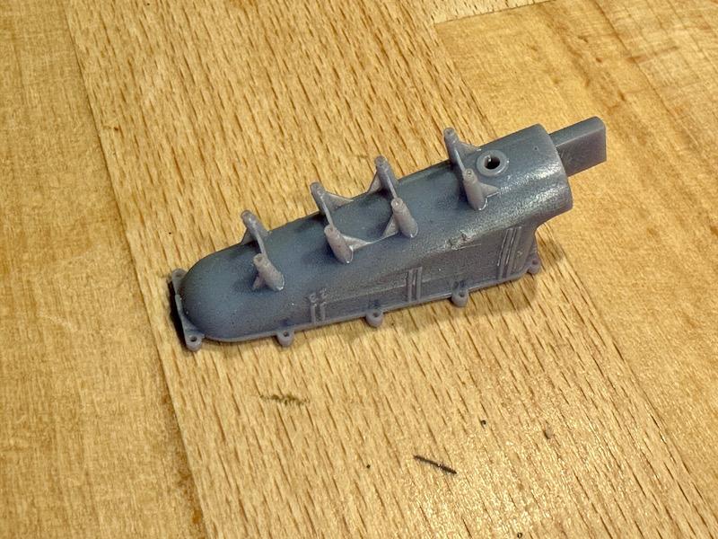
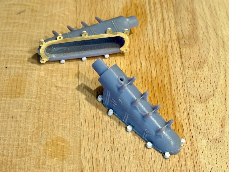
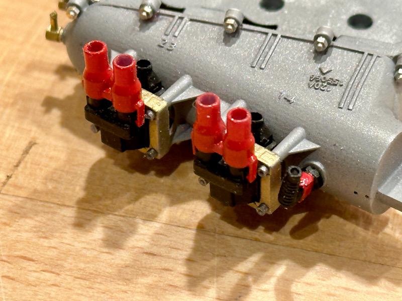
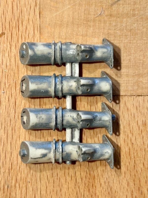
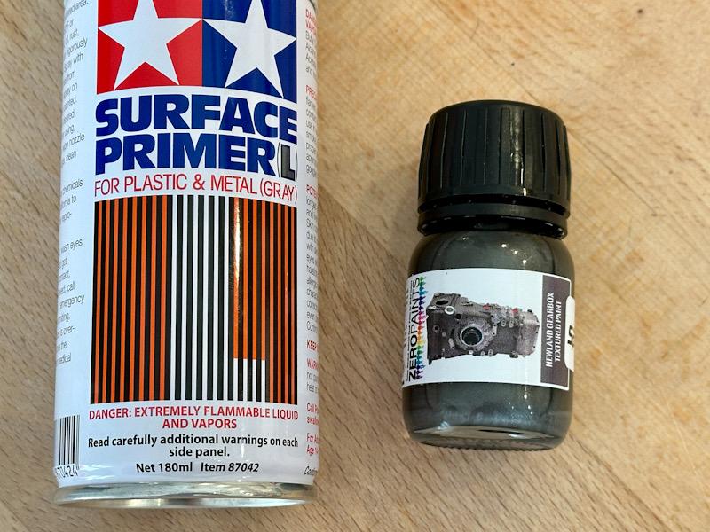
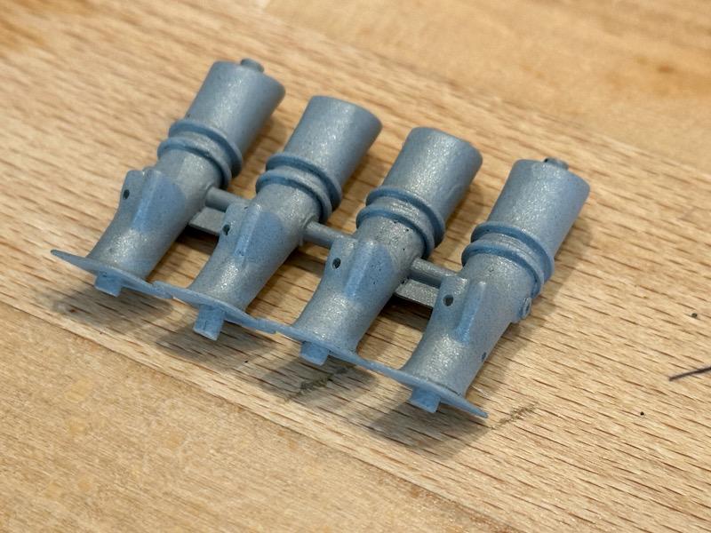
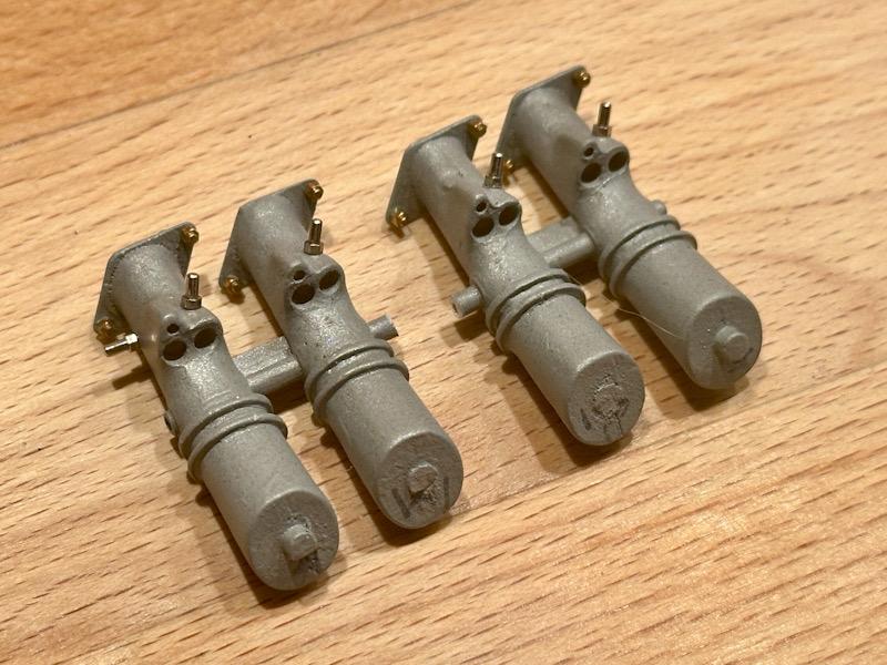
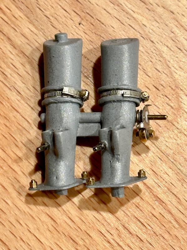
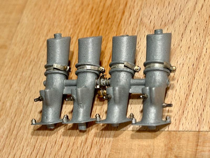
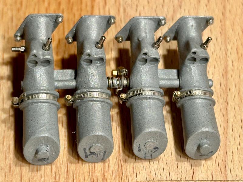
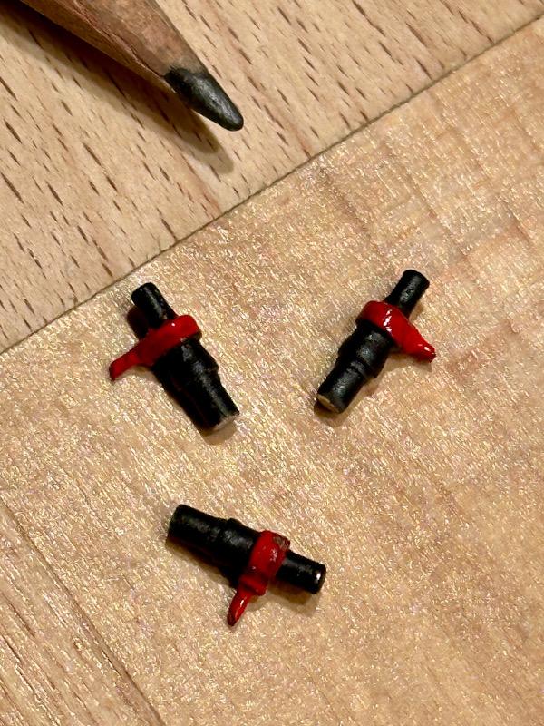
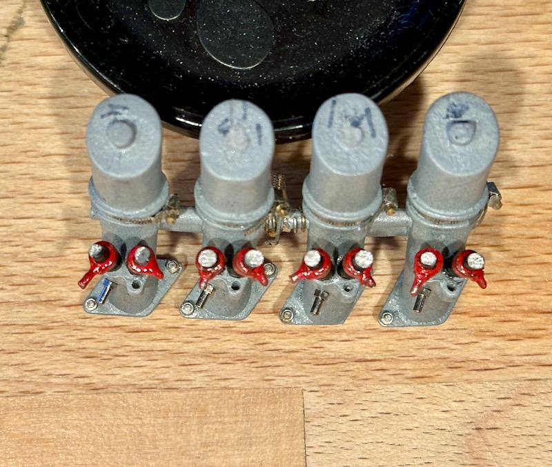
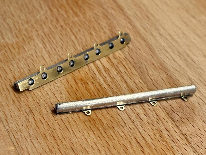
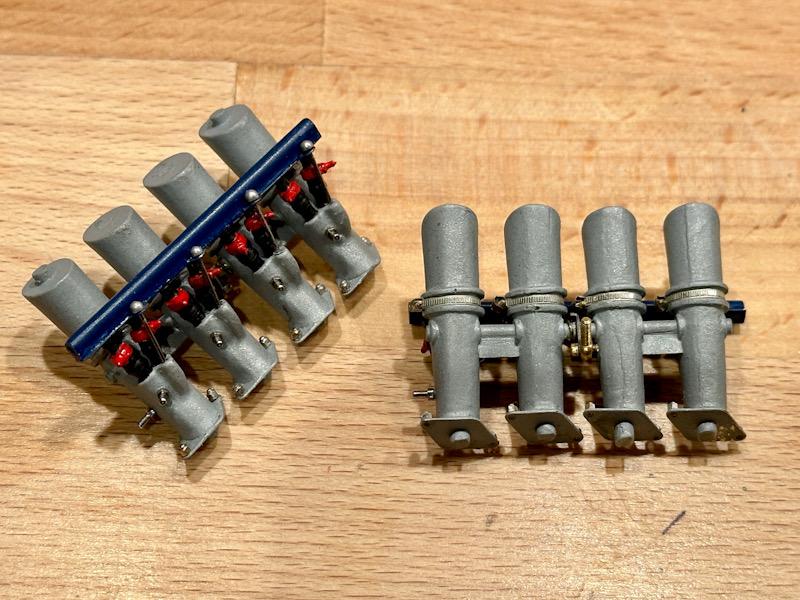
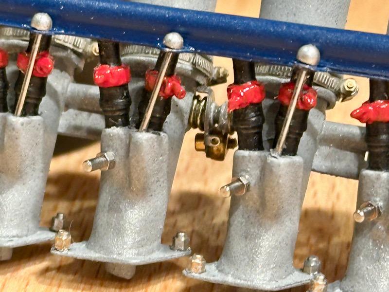
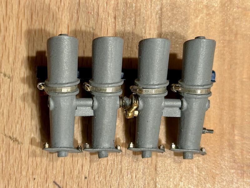
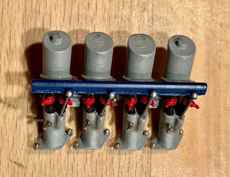
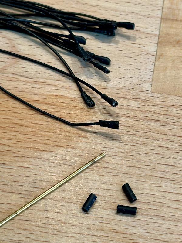
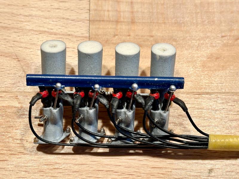
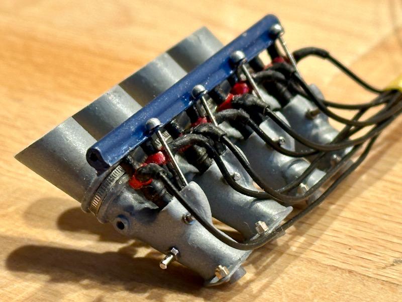
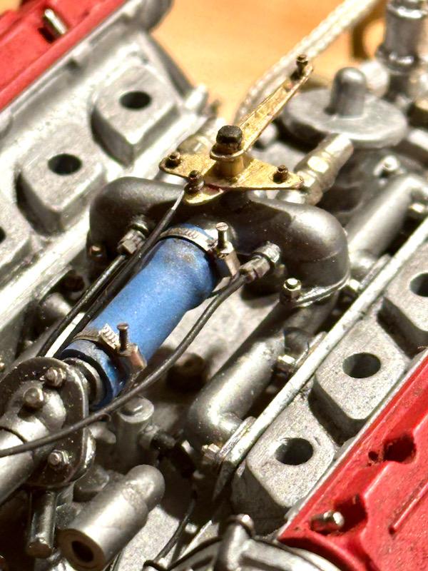
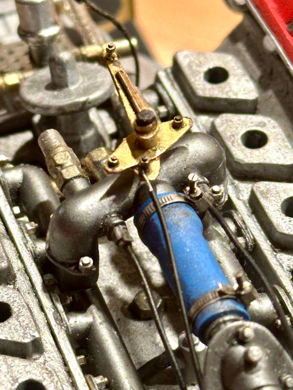
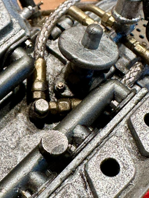
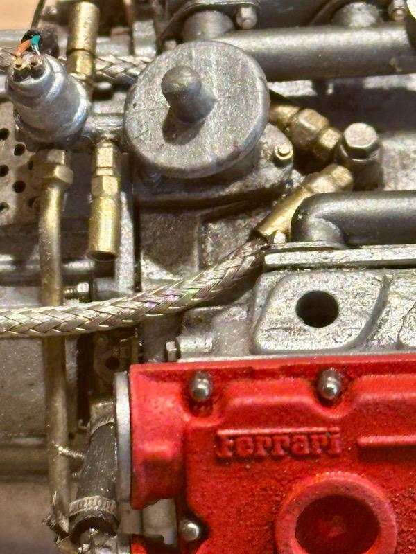
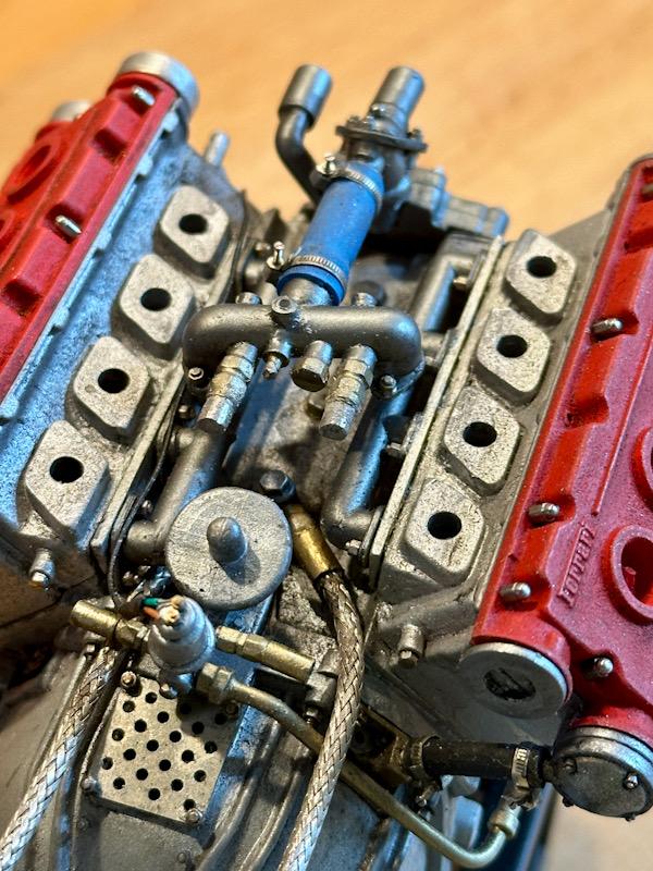
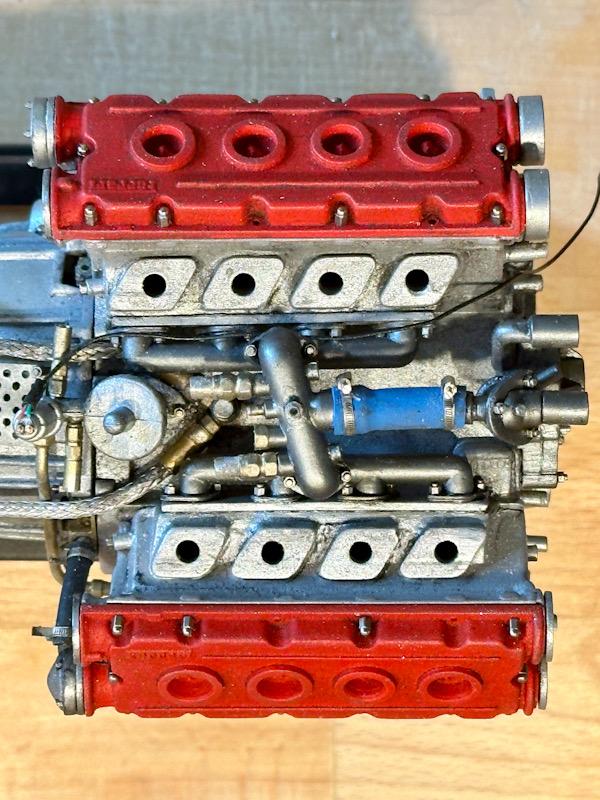
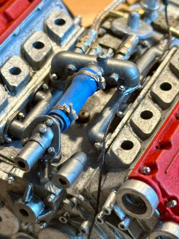
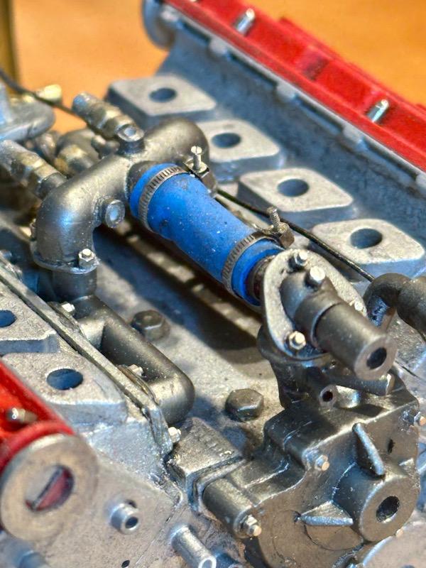
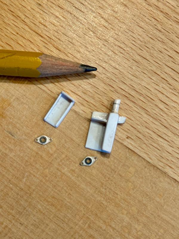
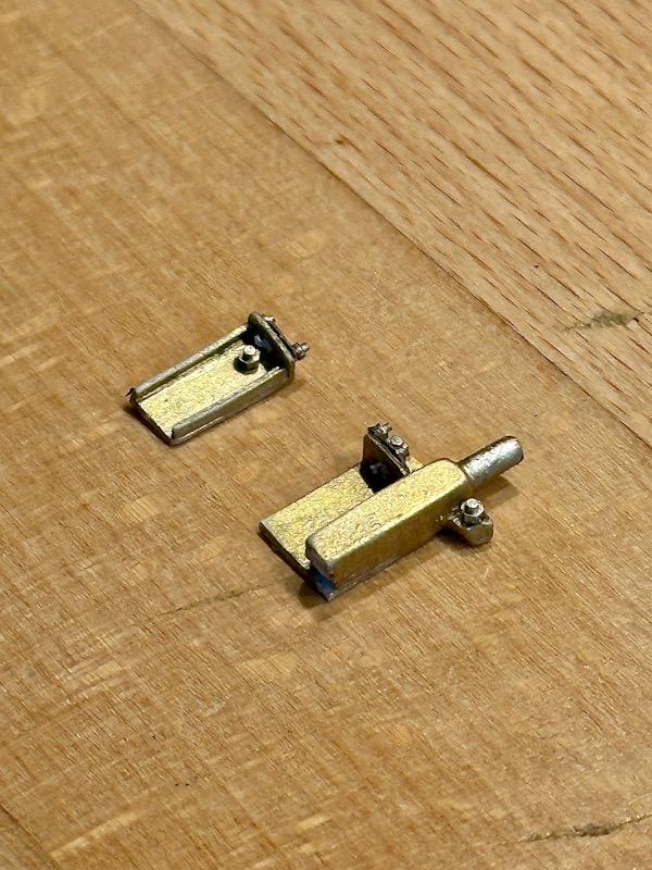
Today, work continues on the engine being installed in the car. Specifically, we’re focusing on the intake system. Here is the starting point from the Pocher kit. Pocher didn’t exactly cover themselves in glory here. The biggest flaw is in the area of the intake manifold. The entire injection system and throttle control are missing. Fortunately, Autograph paid a lot of attention to this area. For the intake manifold, the transkit includes resin, photo-etched, and white metal parts. In the real car, two intake channels are connected. Accordingly, I connected the resin parts using a 2 mm ABS pipe. Thin connecting ribs were also added. The engine-side flange is made from etched parts. Since the surface of the resin parts had some imperfections, the parts were filled, primed, and sanded. The parts were then sprayed again with Tamiya primer. After that, a thin layer of “Hewland Gearbox Textured Paint” by Zeropaints was applied. This brought the color and surface texture very close to the original. Next, initial details like screws and nipples were added. To add throttle control, the intake channels were split in the middle. At the connection point between the intake manifold and the plenum, there are hose clamps. Autograph’s transkit provides nice etched parts for this. The throttle control in the original is very complex, featuring many components, adjustment screws, and multiple springs. I created a simplified version. The base is an etched part from Tommaso’s Testarossa transkit, which is used there for the throttle. Luckily, Tommaso included two extra parts on the plate. The screws are from Knupfer, and I made the spiral spring from thin craft wire. Here’s the finished mechanism. The two intake manifold segments were then glued back together. Next up were the fuel injectors. Autograph includes white metal parts for this in the transkit. These were painted satin black and red. The injectors were then glued into place. Since the top of the injectors connects to the fuel rail, I sanded the top ends flat. The fuel rail is made of a combination of white metal and etched parts, which were glued together. Then, the rails were painted blue. I made the front mounting pins from sewing pins. Here are some pictures of the mounted fuel rail. Another detail is the wiring of the injectors. I made the connectors from heat-shrink tubing. Here are the finished intake manifolds. To ensure clean assembly with the upper plenum later, I sanded the contact surface flat. That’s it for today. See you soon, Your Ferrarifan
-
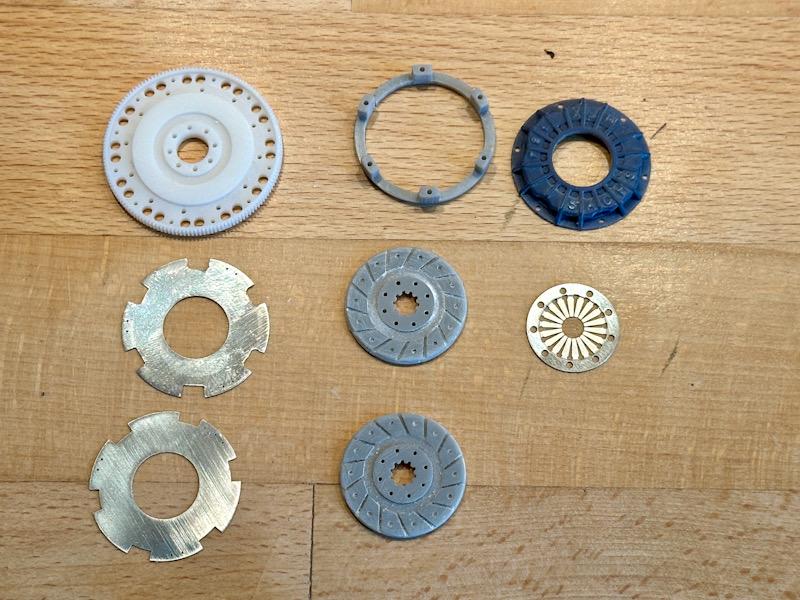
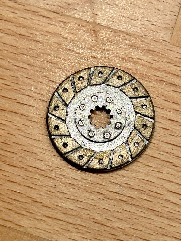
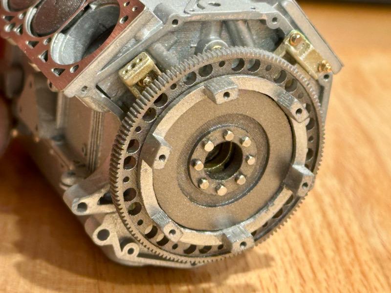
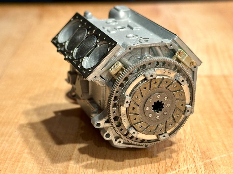
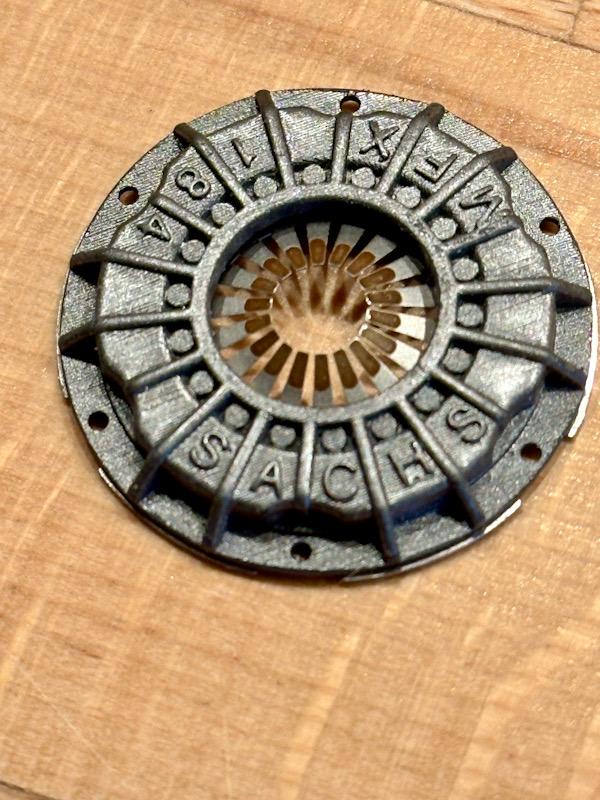
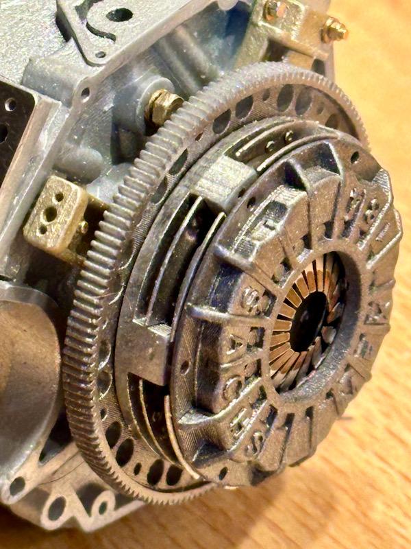
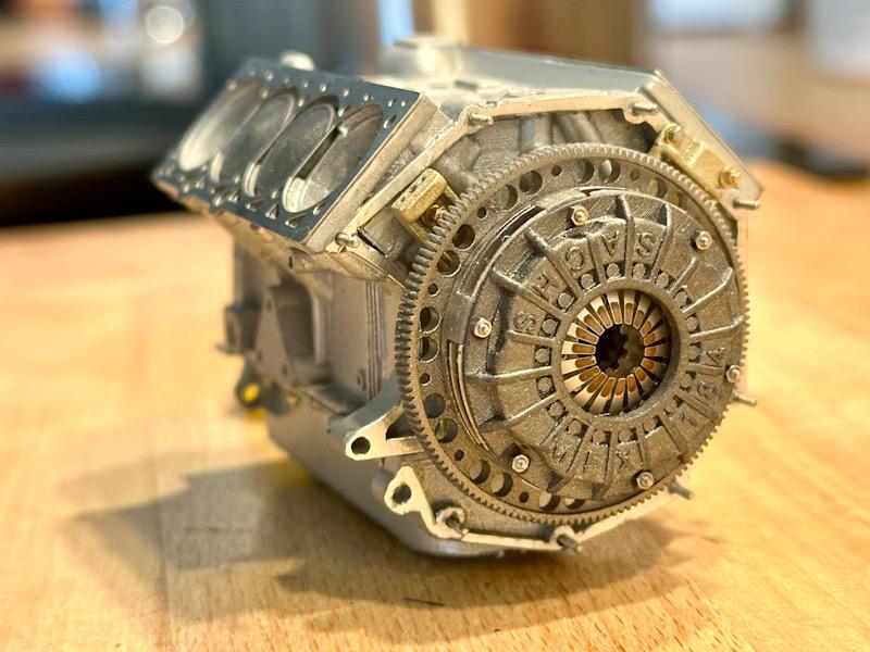
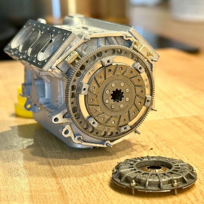
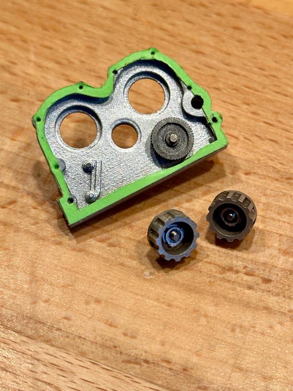
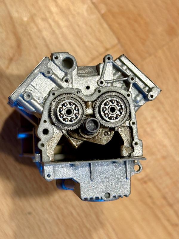
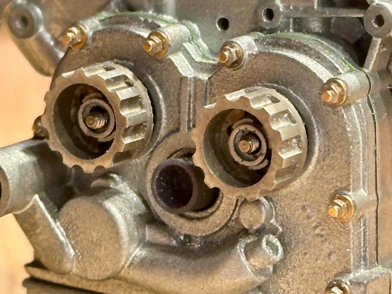
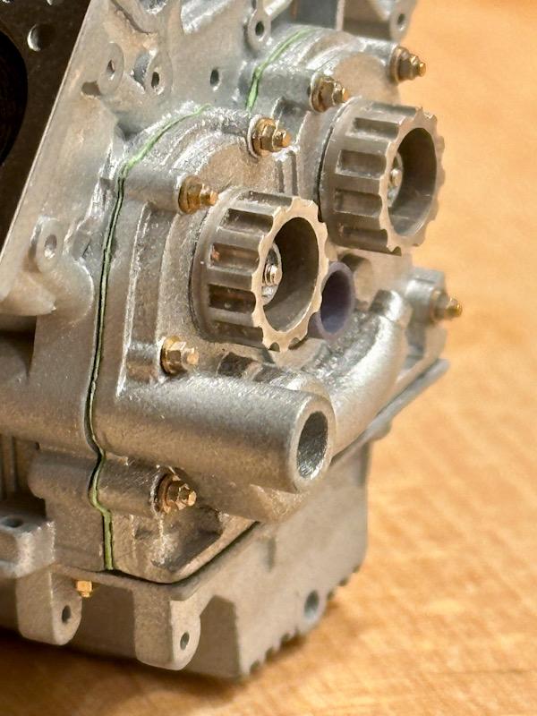
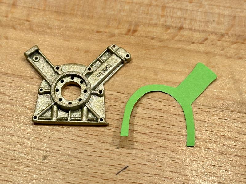
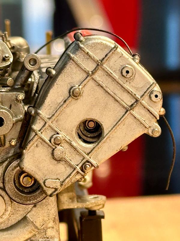
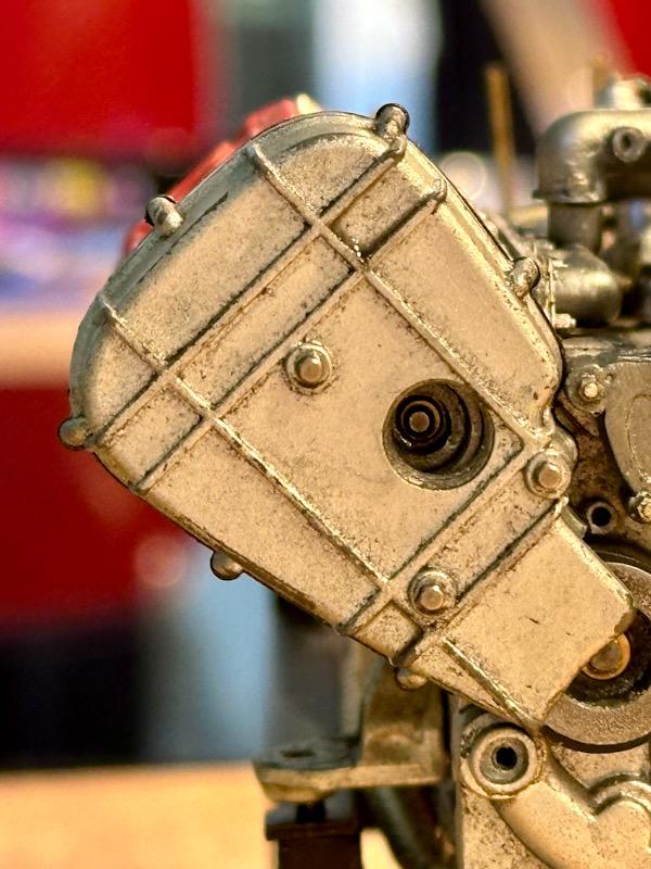
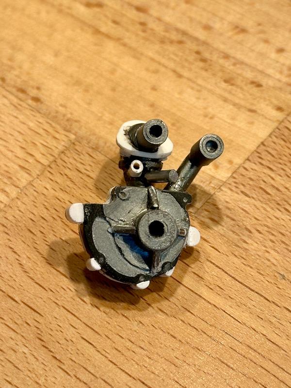
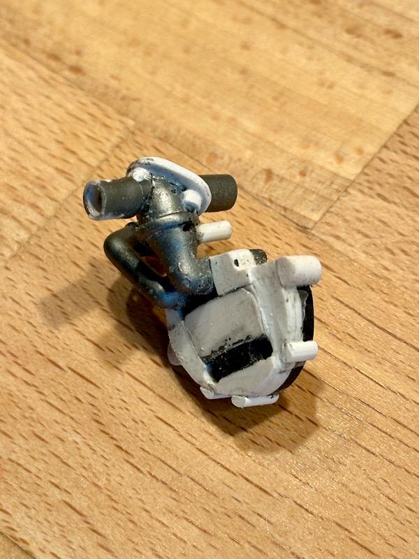
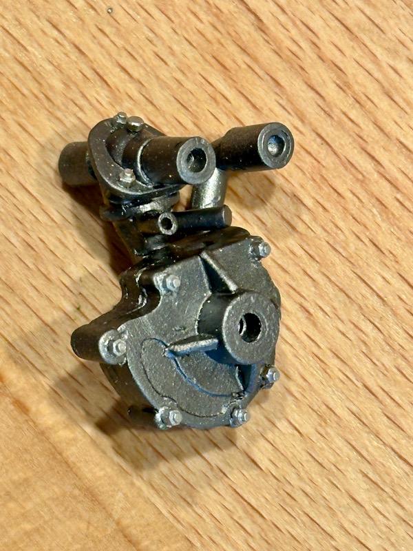
After a long break, it’s time to continue. The next construction stage is the two-disc dry clutch for the standalone model of the engine. Tommaso has once again created very detailed 3D-printed and etched parts. The parts were painted using different Metal Colors from Vallejo. The lining of the friction discs was slightly roughened and then painted with True Metal Paste from AK. To increase the level of realism, I added rivets using etched parts from Top Studio. Once all the parts were painted, assembly began. Step 1 involved mounting the flywheel and the clutch cage. The screws used to attach the flywheel to the crankshaft are from Autograph. Next, the friction discs and the intermediate plate were installed. Following that, the clutch housing, the pressure plate, and the diaphragm spring were assembled. Since I want to remain flexible when displaying the standalone engine, the clutch housing can easily be placed over the bolts. The next step involves the crankcase cover on the side of the belt drive. While the Testarossa engine uses two timing belts to drive the valves of both cylinder banks directly from the crankshaft, Ferrari’s engineers took a different approach with the F40. Here, the crankshaft drives two gears, which in turn power the timing belt pulleys. These gears, along with the gear driving the oil pump, are located behind this crankcase cover. Tommaso’s transkit has accounted for nearly every detail. Here is the painted cover with the screws. To enhance realism, I replicated the gasket using green paper. Even though the following details will no longer be visible later, it was a lot of fun to assemble these parts. Here is the gear for the oil pump. Tommaso even included the ball bearings for the gears. The cage is a 3D-printed part into which small metal balls are pressed. After assembling the gears and bearings, the cover was installed, and the timing belt pulleys were mounted. In the side view, you can clearly see the green gasket, just like on the original. Finally, here are some images showing the current construction status of the standalone engine. That’s it for today. Next time, we’ll continue with the engine that will be installed in the car. See you soon, Your Ferrari fan
-
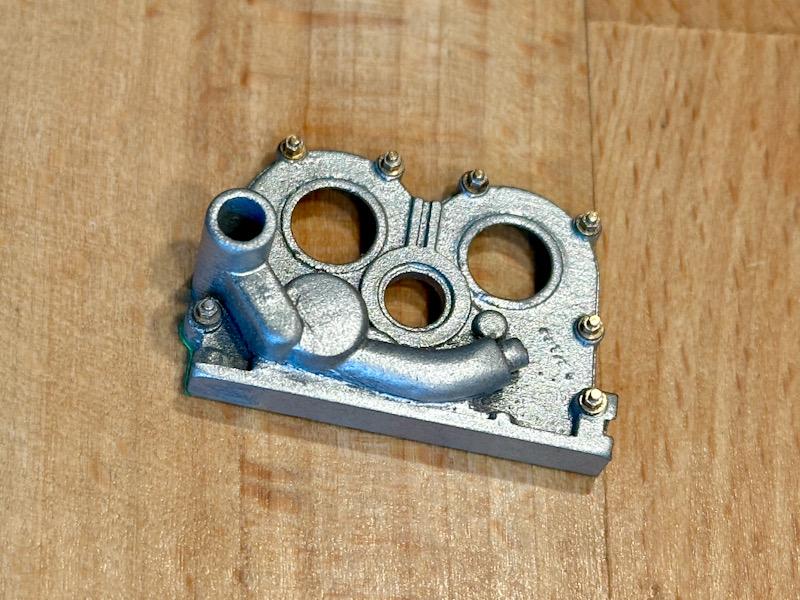
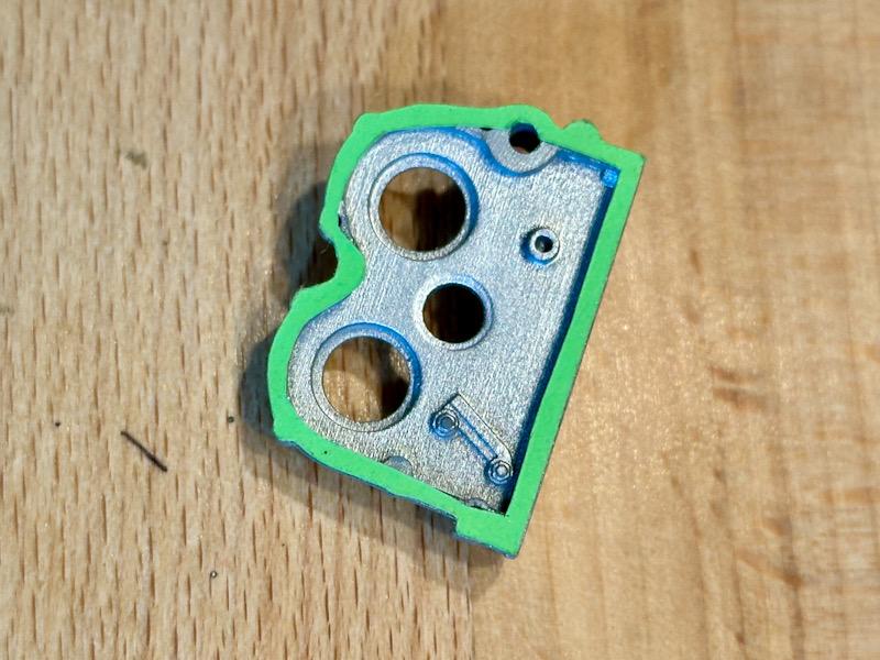
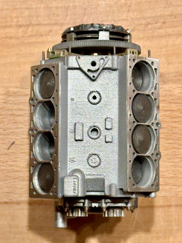
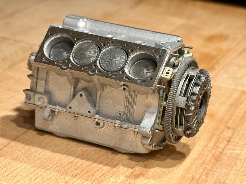
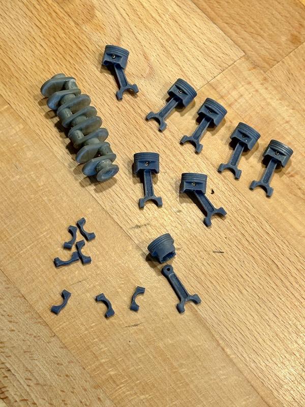
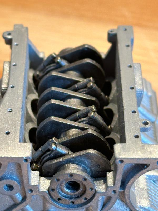
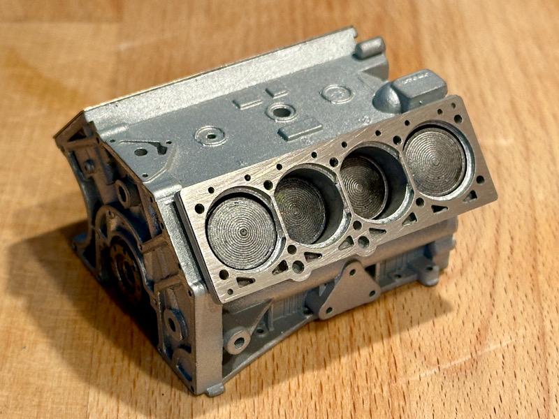
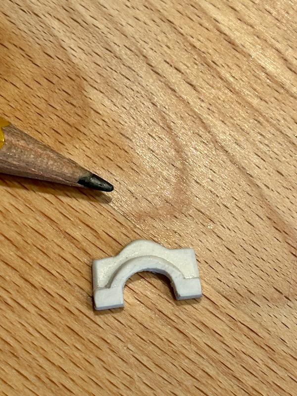
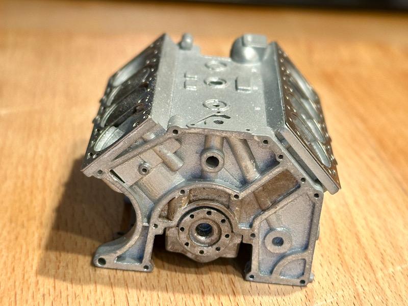
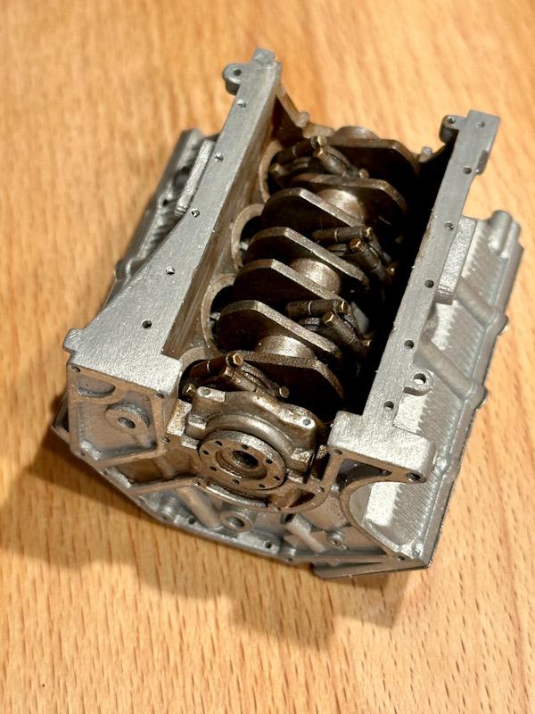
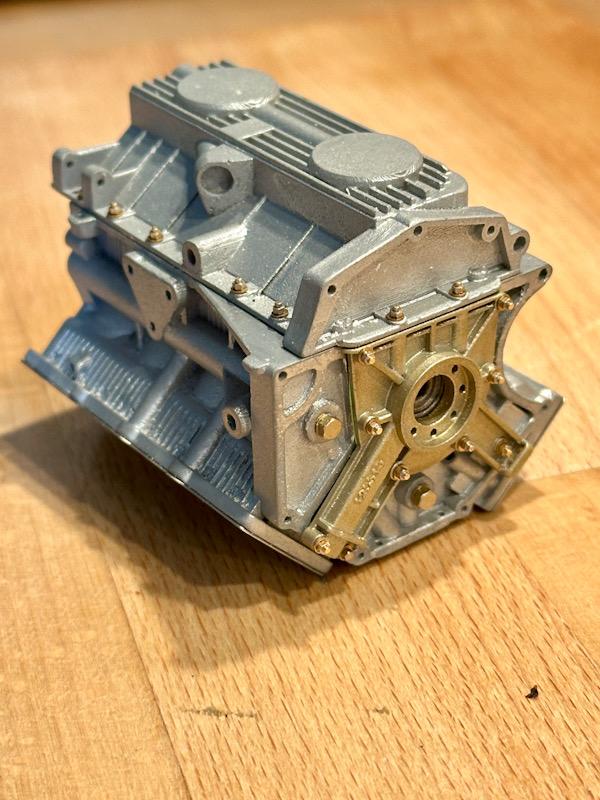
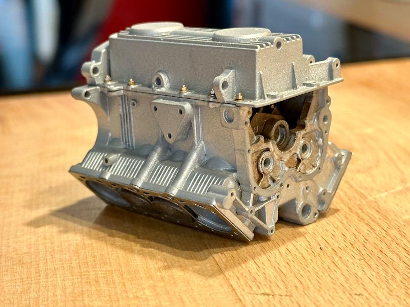
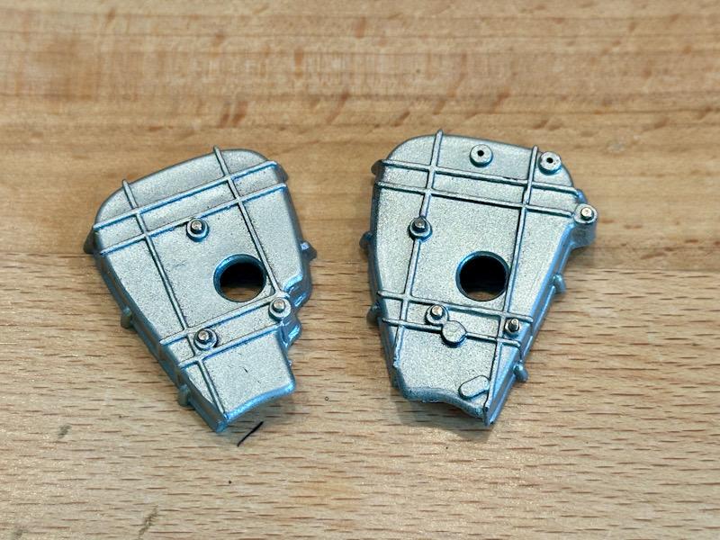
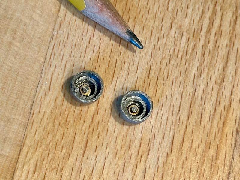
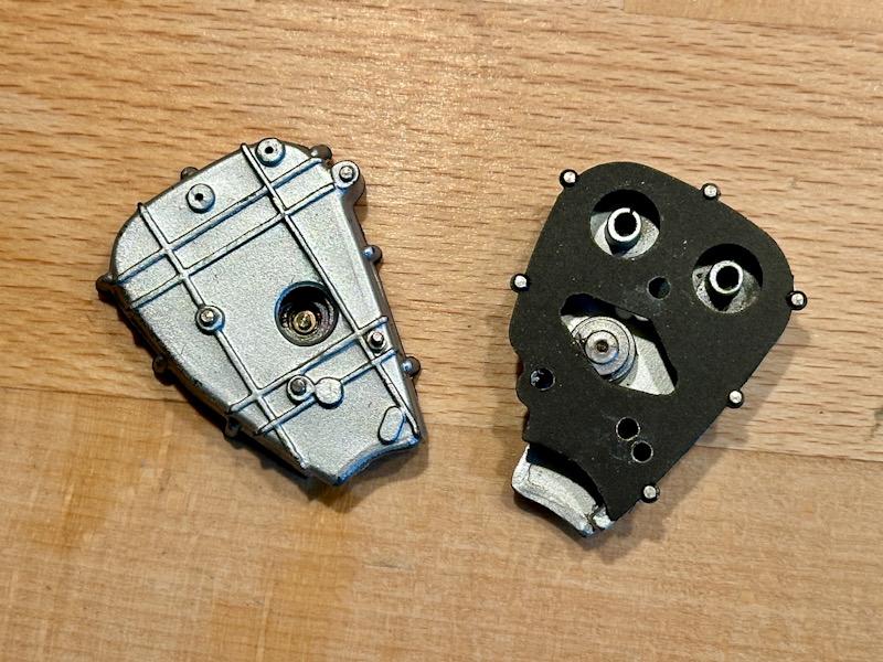
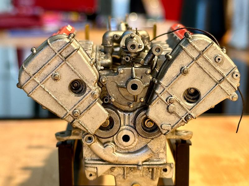
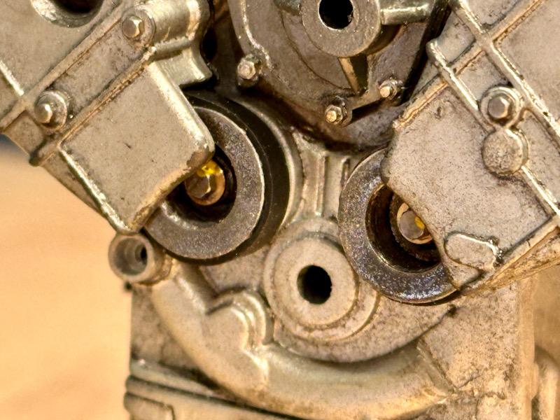
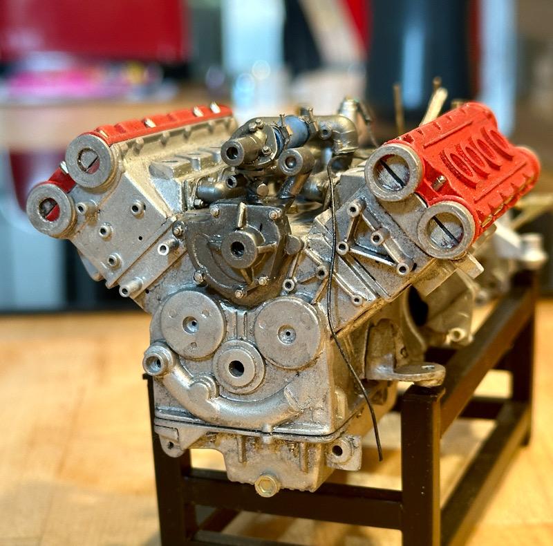
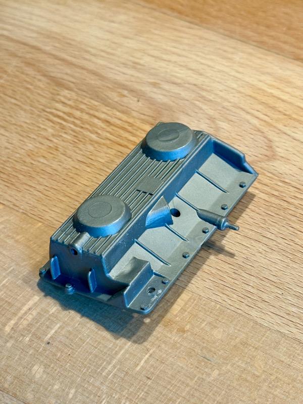
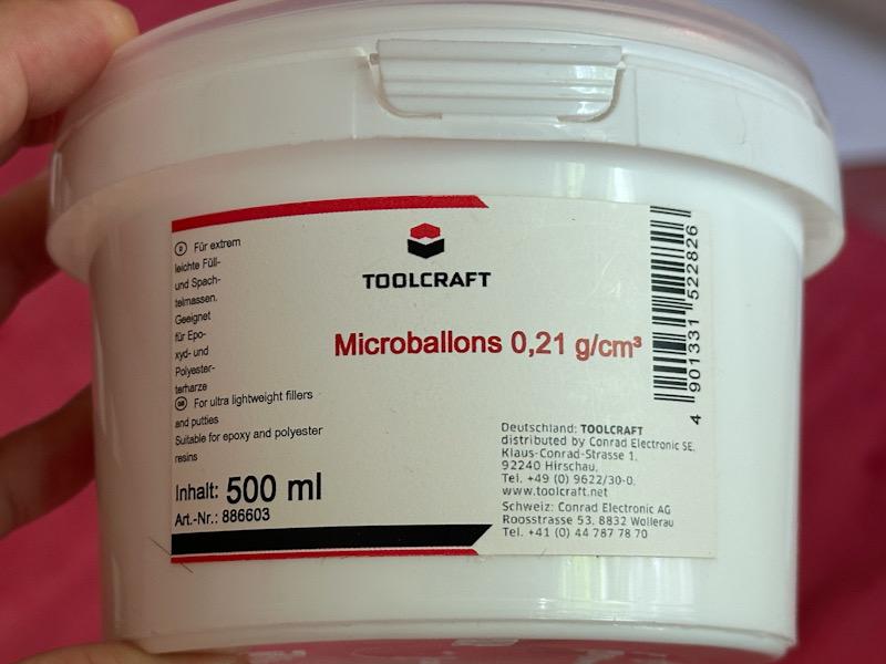
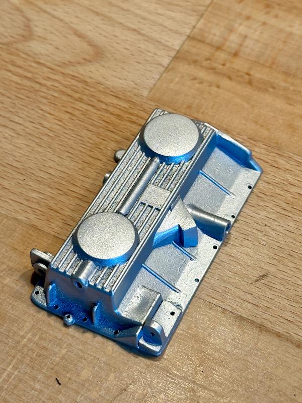
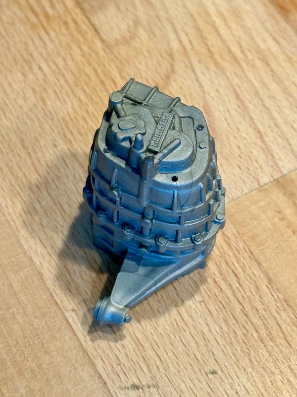
Today, I am starting with the standalone engine, which is part of the transkit by Tommaso Iuele (Transkit Modelcars). As with the Testarossa, Tommaso has created a completely new engine made from 3D printed parts, etched parts, and turned parts. The print quality is somewhat better than on the Testarossa, but some parts still have strong layer lines. The original engine is made of aluminum, with the cylinder liners pressed in. Unfortunately, Tommaso forgot the liners in his model. Even though this detail won't be visible later, it bothered me, especially since Tommaso included the pistons and connecting rods in the model. Because Tommaso made the pistons larger in diameter, I couldn't recreate the liners without significant modifications. I chose a middle ground and at least closed the central webs. Furthermore, Tommaso made undercuts in the crankcase at the transition from the sidewall to the banks, which are not possible in casting and thus look different on the original. I filled these areas with Revell's Plasto putty. After drying, the excess putty was removed with a scalpel. Then the engine was painted. Here, I used the same approach as for the built-in engine. Primer with Tamiya Primer, followed by Aluminum from Vallejo's Acrylic Metal Color series mixed with Micro Balloons to get a cast-like surface. However, I then sanded all sealing surfaces again and painted them with True Metal Silver from AK. This makes these surfaces smooth and shinier. As mentioned above, the transkit also includes the crankshaft, connecting rods, and pistons. Even though these parts won't be visible later, I couldn't resist painting them neatly as well. The connecting rods were bolted with M 0.8 screws. Regarding crankshaft bearings, Tommaso omitted the inner bearings in the crankcase. He also forgot the bearing caps on the outer bearings. I then simplified these from ABS. The next part was the gearbox-side cover, which is necessary for the oil circuit and serves as a carrier for the TDC sensors. The cover was painted with Tamiya's Titanium Gold. To increase realism, I replicated the gasket from green cardboard. For screws, I used M 0.8 screw imitations and washers (both from Knupfer), with the brass screws repainted using True Metal Color Steel. The next step was the oil pan. Here too, Tommaso made design errors. There are again undercuts on the oil connections, and in the area of the fastenings, he made circular thickenings. I filled the undercuts with putty again and sanded away the thickenings. Then the oil pan was painted like the crankcase. Afterwards, the oil pan was attached to the crankcase with super glue. Again, I used M 0.8 screw imitations and washers from Knupfer. That's it for today. Next time, the clutch is up. See you soon, Your Ferrarifan
-
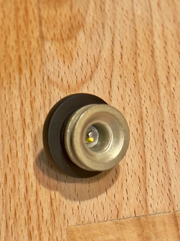
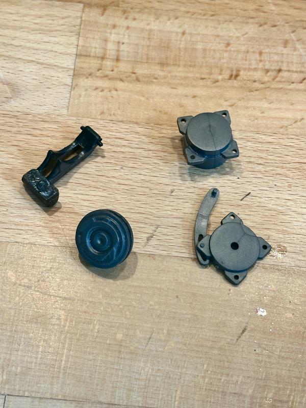
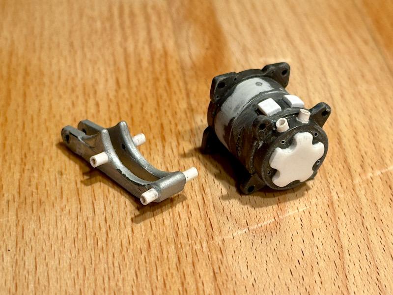
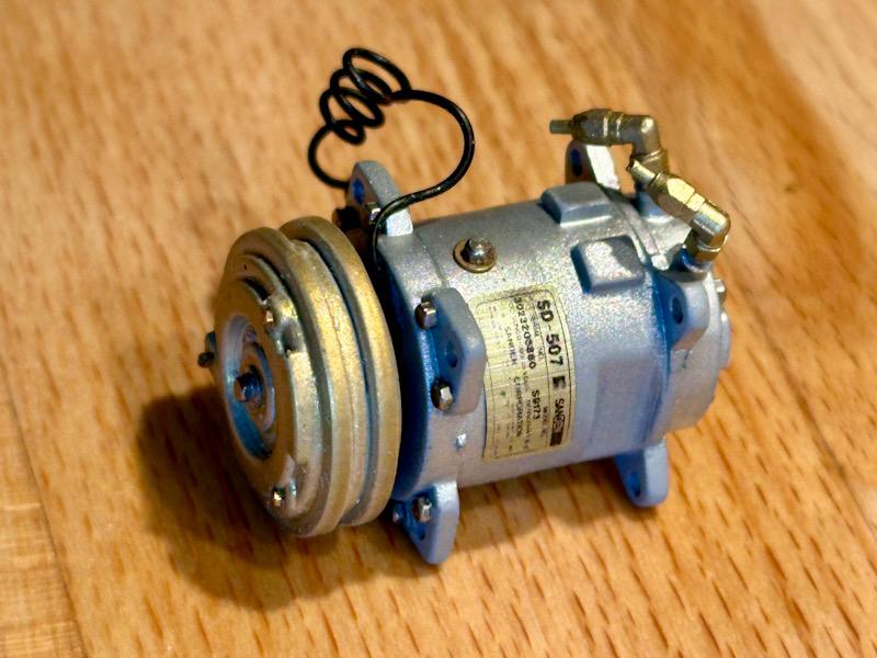
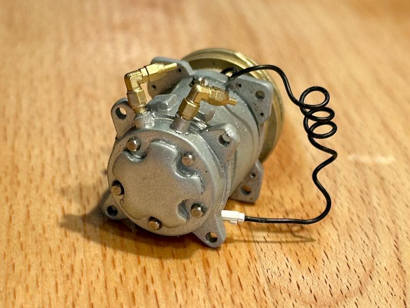
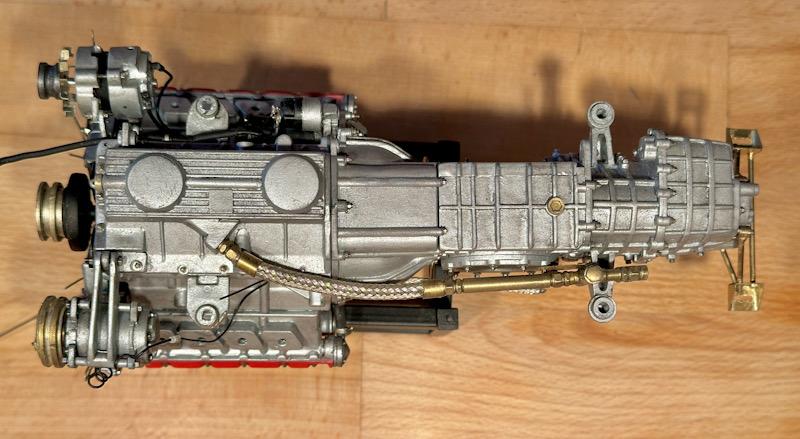
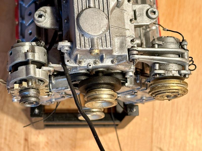
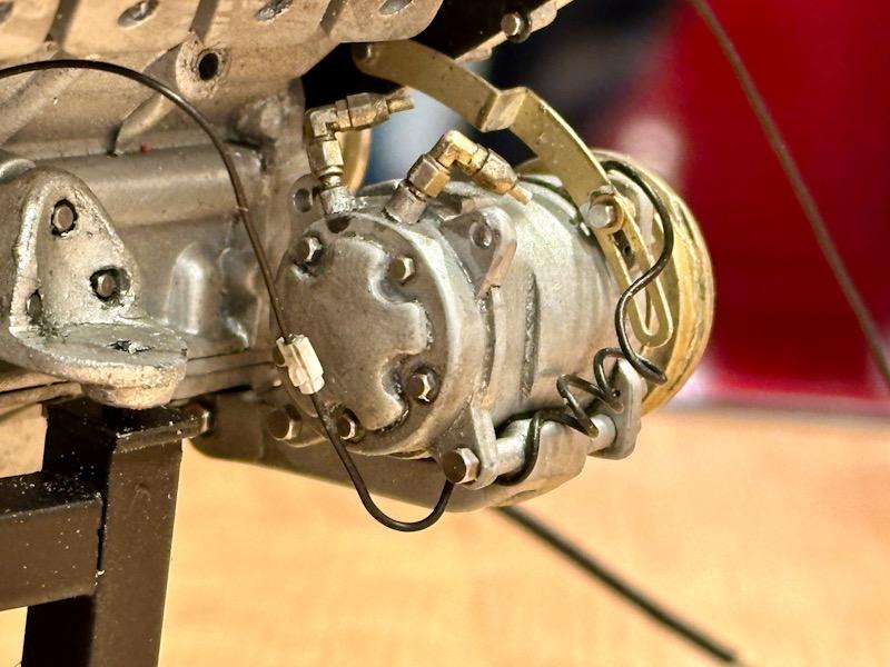
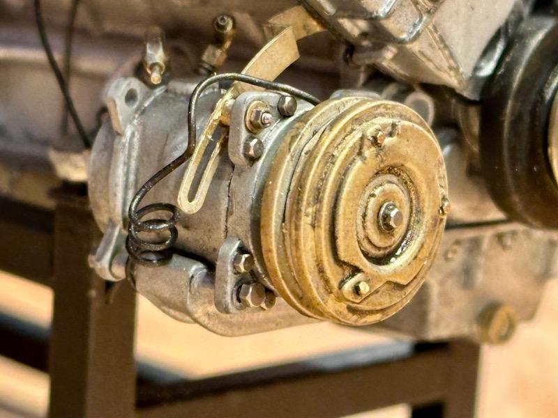
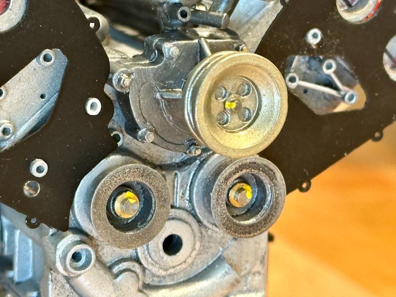
Next component is the main pulley with the vibration damper. In the Pocher model, the vibration damper is slanted sideways. However, this does not match the original. Therefore, I clamped the part in a Dremel and ground down the side surface. Since I added the lower pulleys for the camshaft drive, the entire belt drive for the water pump, alternator, and air conditioning compressor shifts forward. Accordingly, I extended the vibration damper backwards. Afterwards, the main pulley was painted, and the fastening screw was added to the front. To ensure that it is properly tightened, I marked it in yellow.? Next, we move on to the air conditioning compressor. As with the alternator, many details are missing here as well. After removing the molded-in holder, I extended the housing. On the back side, I expanded the end plate and added the connections for the lines. The holder was also reworked, although I did not completely adhere to the original. Then, everything was painted. Subsequently, the missing screws, connection fittings, and the electrical connection cable were installed. To enhance realism, I created the original sticker in Photoshop and printed it on a printable metal foil. Then everything was given a light wash and mounted on the engine. The upper holder is again a photo-etched part from the Autograph Transkit. To ensure the belts align properly, I had to mount the alternator differently. Finally, a few detailed shots of the air conditioning compressor. That's it for today. See you soon, Your Ferrarifan
-
Thanks for following! More details to come?
-
Thanks for the compliment!?
-
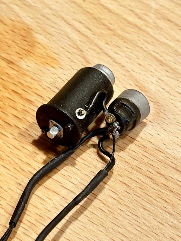
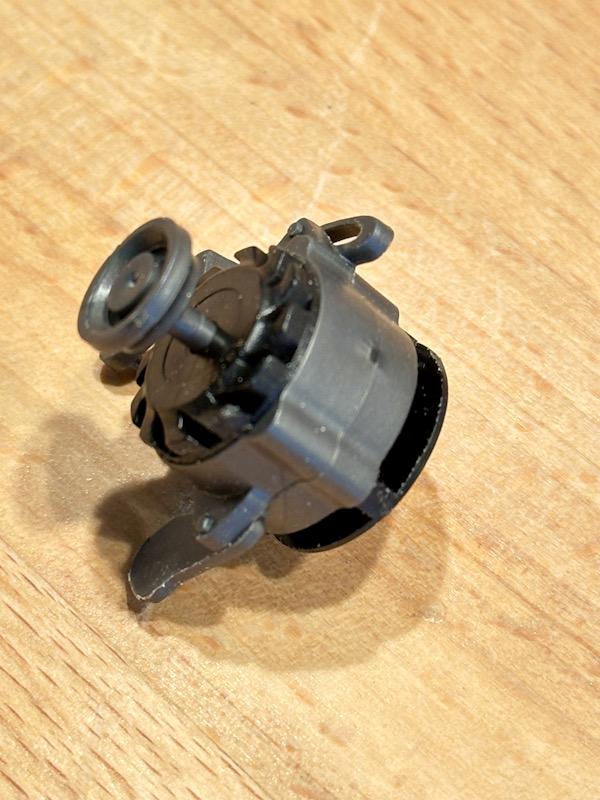
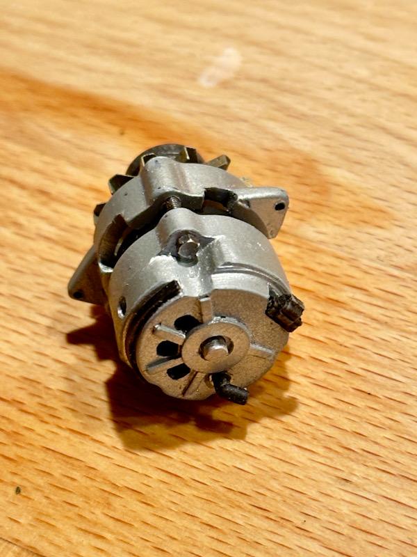
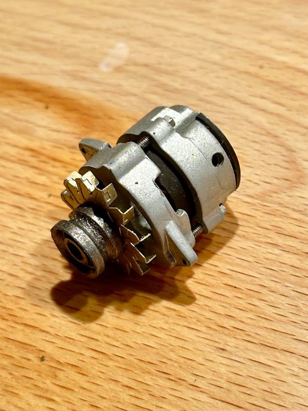
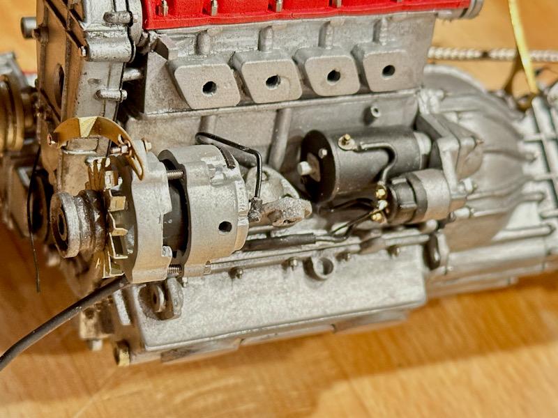
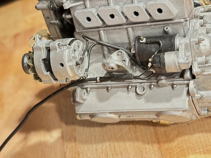
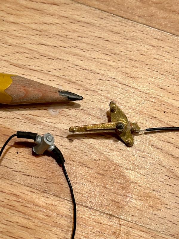
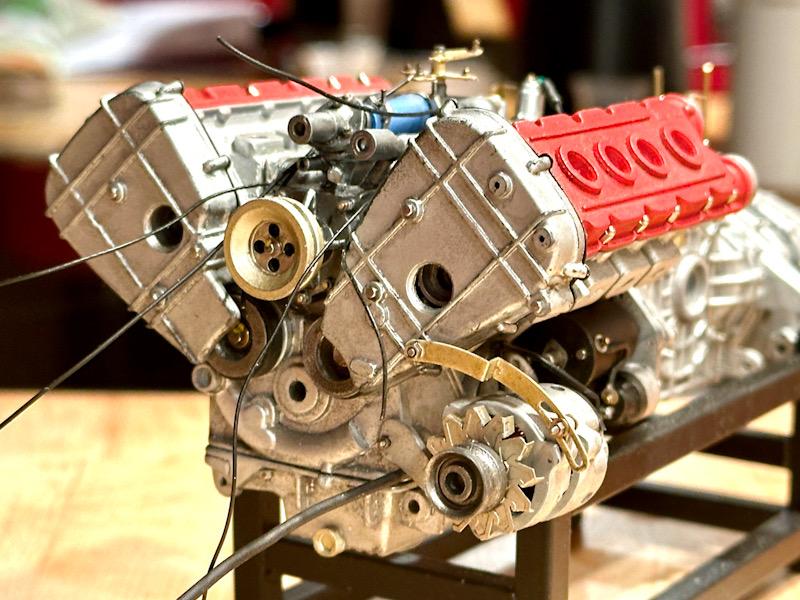
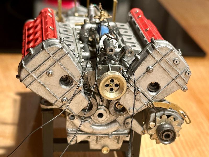
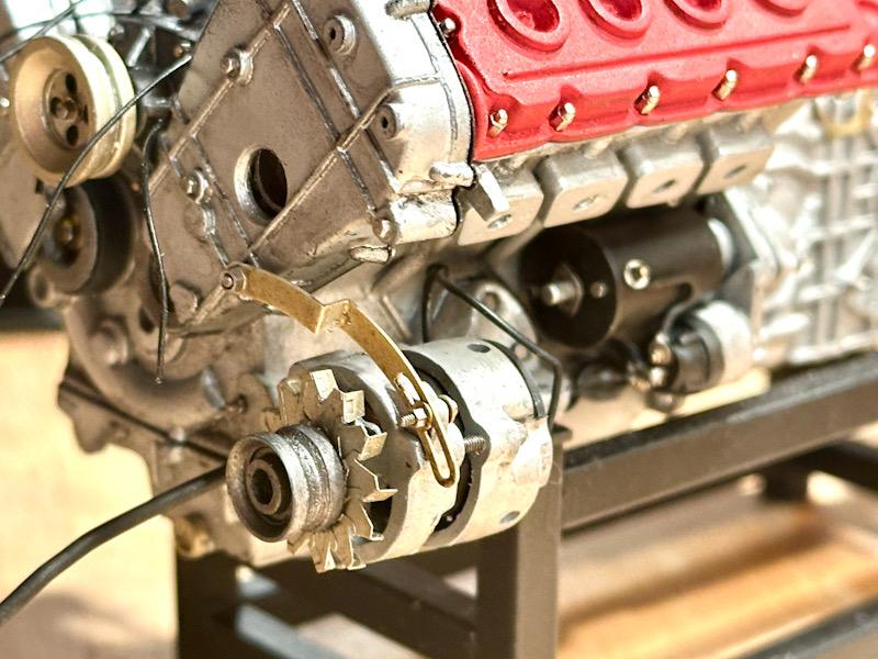
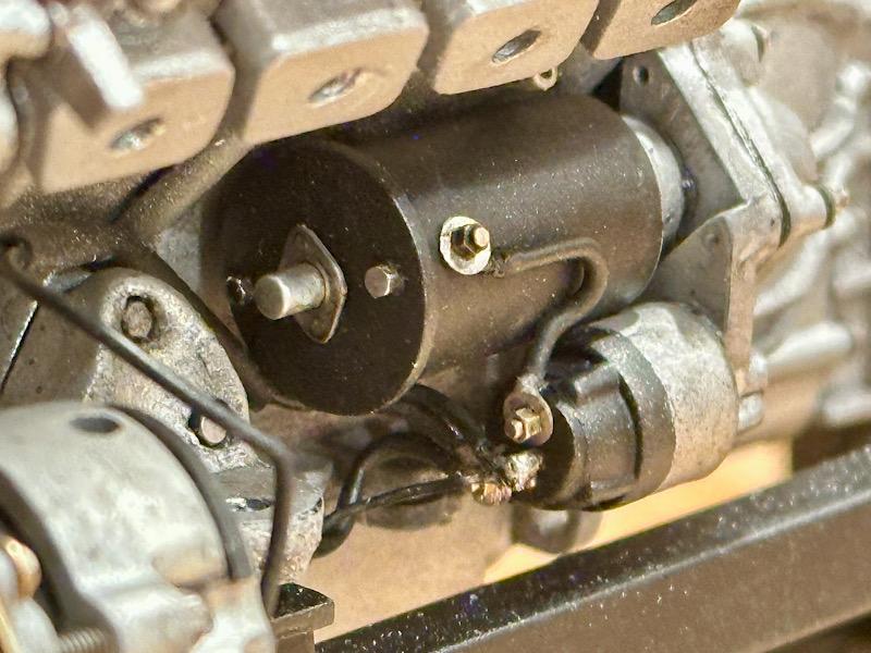
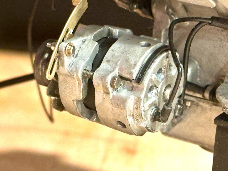
Today, it's the turn of the starter and the alternator. The starter was only slightly modified. On the back, the stub shaft was replaced by a steel pin. A photo-etched part leftover from the Testarossa and a few screws complete the whole thing. The wiring to the starter and alternator was a bit more work, as I soldered some of the wires with small washers. For the alternator, I went all out again. The base from the Pocher kit is, well... I removed the molded brackets and split the housing. Then, ventilation openings were made on the front. Clearances for the screws were made on the back, and ventilation slots and ribs were added. A spacer was made in the middle. Even though the detail won’t be very visible, I made a simple coil with windings. The drive wheel was also reworked. In the middle is a shaft I made from a steel pin. The fan wheel is a photo-etched part from the Autograph transkit. The assembly is done using 3 screws from Autograph. Finally, connectors for the connection cables were added. Then, the parts were assembled with screws, nuts, and washers (all from Autograph). The Autograph transkit includes a nice photo-etched part for one of the brackets. Next, the throttle linkage was on the agenda. This detail is missing in both the basic model and the transkit. I made the lever from ABS and detailed it with screws. Another detail is the two knock sensors. I kept these fairly simple. The parts were then quickly assembled. Afterwards, the newly installed parts were given a light wash. Here are a few close-ups. In this construction step, I also mounted the two water temperature sensors that sit on the collector pipe. That’s all for today. See you soon, Your Ferrarifan
-
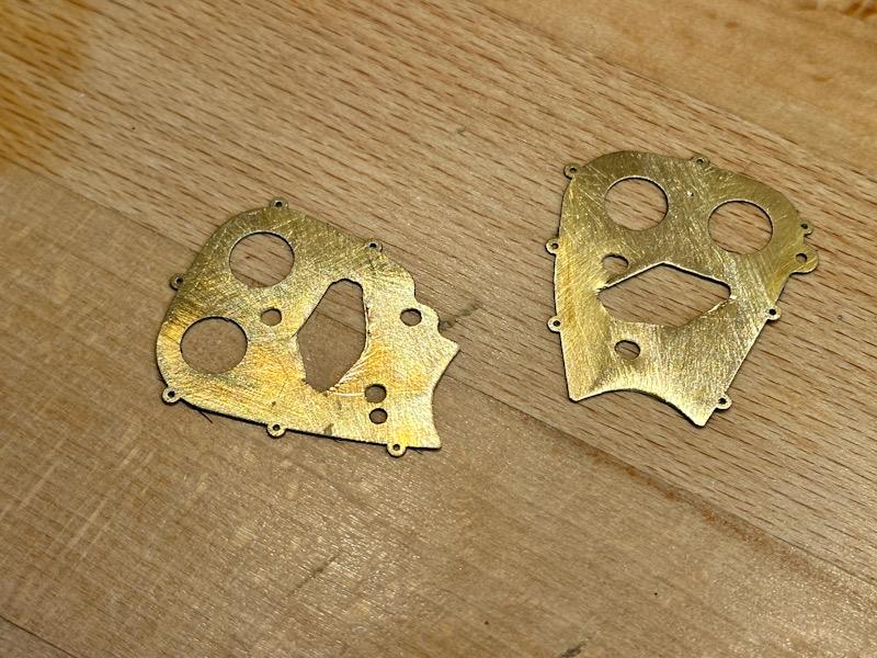
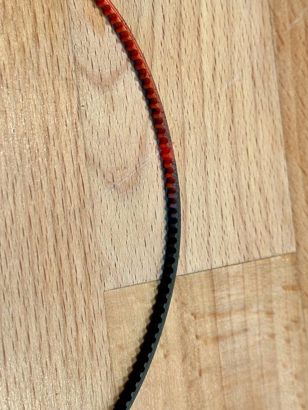
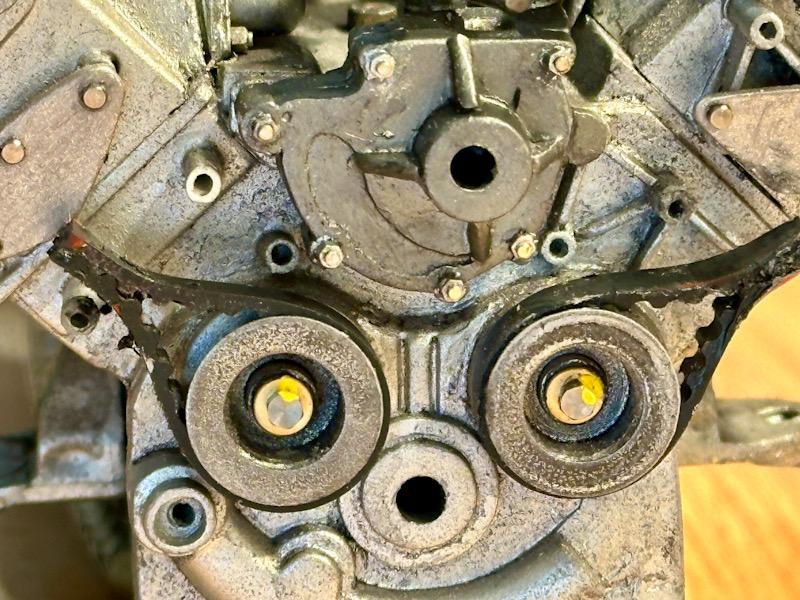
As previously announced, today it's the turn of the timing belt drive of the camshafts. Since the two lower pulleys are missing in the Pocher model, I made simplified pulleys from "leftovers" from the Testarossa. They were then painted with Vallejo Steel and glued on. To protect the timing belt as much as possible, there are cover plates on the back of the belt drive. Autograph made etched parts for this. Since I added the mounting bosses for the timing belt cover and the tension rollers to the crankcase and cylinder heads, the etched parts had to be adjusted accordingly. Additional holes were drilled in the area of the bosses, and the area where the tension rollers are mounted was also cut out. Furthermore, the lower area was cleared to mount the pulleys. Then the plates were primed and painted black. Here is a picture of the trial assembly. Even though this area will no longer be visible after the engine is installed, I decided to depict the outer area of the timing belt. As with the Testarossa, the timing belt from a microwave is used. This was painted black and glued to the pulleys. The timing belt covers were slightly modified. Molded screw heads were removed and replaced with real screws. In the area of the tension rollers, there is an opening in the original. Since this was missing in the Pocher part, the area was drilled out. The lower area on the back was cut out for the timing belt, as in the original. The tension rollers were also made from leftovers from the Testarossa. Then the rear cover plates and the tension rollers were mounted on the covers. Finally, the assembled covers were mounted on the housing and the area was given a stronger wash. To conclude, here are a few detail pictures of this area. That's it for today. See you soon, Your Ferrari fan
-
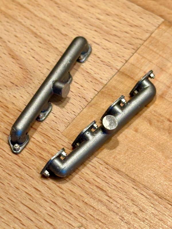
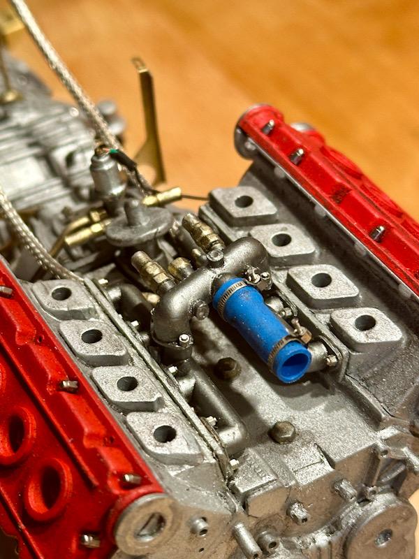
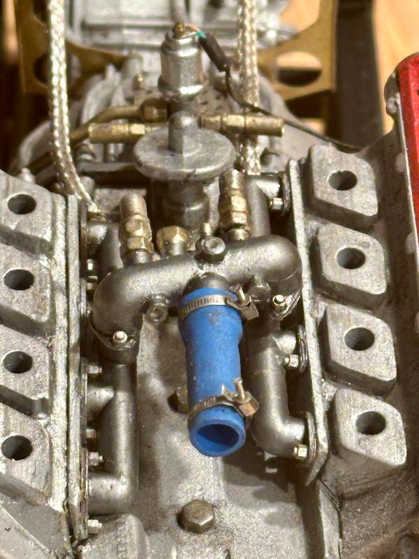
Today I start with the cooling system for the engine and the two turbos. The Autograph transkit includes nice white metal parts for this purpose. The first part to be made is the T-piece for the turbochargers. As with the oil lines, coaxial cables and ferrules are used for the lines. Next were the two collectors, which are mounted on the sides of the cylinder heads. For this, the transkit includes white metal and etched parts. After gluing the parts together, they were primed and painted in gunmetal. For screws, I used copper imitations from Knupfer, which were then colored with True Metal Steel. Subsequently, the parts were installed and given a light wash. The next step was the bridge that connects the two collectors. The return lines from the turbochargers are also connected here. The main line then goes forward to the water pump. The main part is again made of white metal. The main line is made from a shrink tube. For the hose clamps, Autograph provides nice etched parts and fine watchmaker screws. The bridge was then attached to the two collectors using super glue. Next up was the water pump. To ensure the water pump fits snugly against the crankcase, the back was doubled up. The housing is split at the top, where the thermostat is installed. I sawed apart the injection-molded part and added a screw flange. Then the missing inlet and outlet pipes and screw plugs were added. After the pump was painted, the missing screws were added. Then the water pump was mounted. So that's the current state of construction. Next time, the timing belt and the associated drive gears, tensioners, and covers are up. See you soon, Your Ferrari fan
-
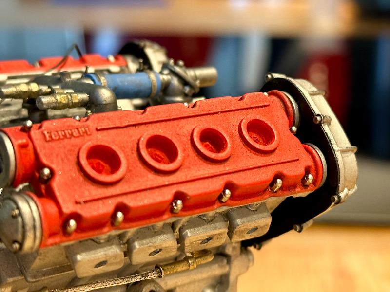
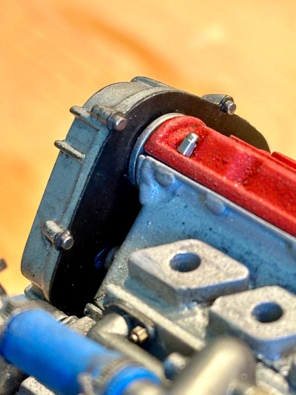
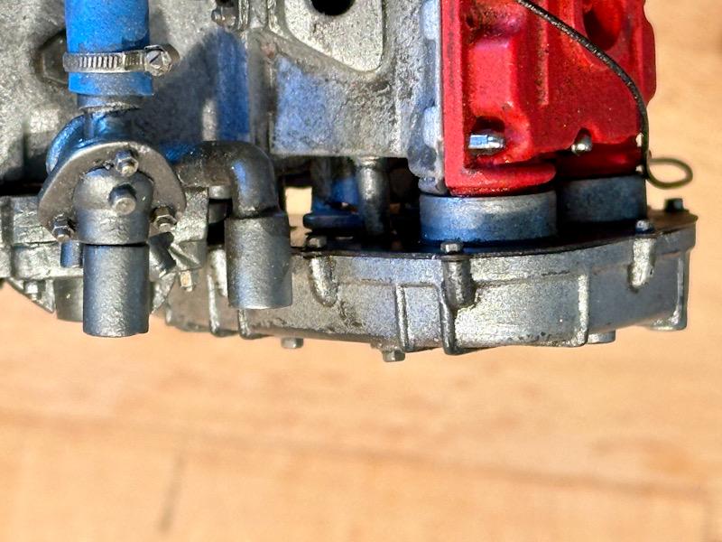
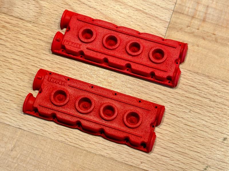
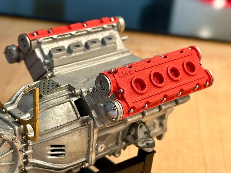
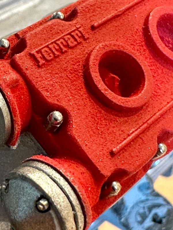
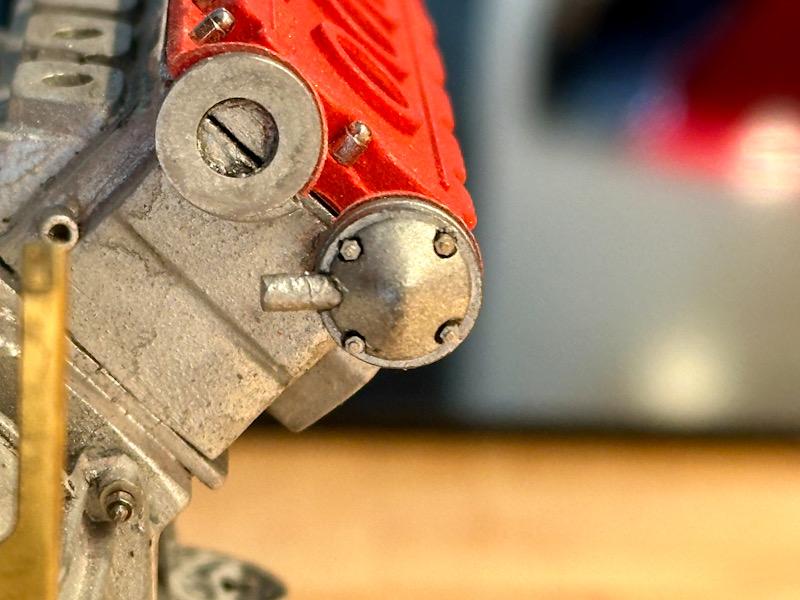
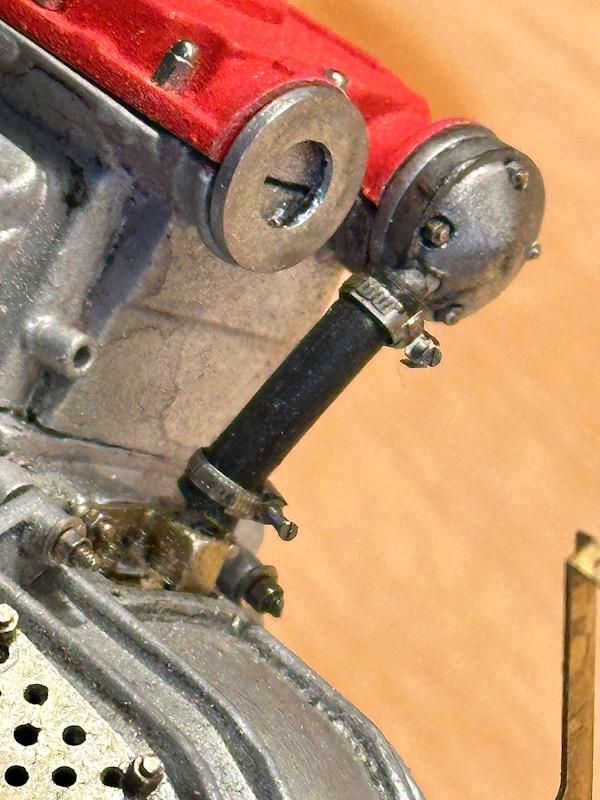
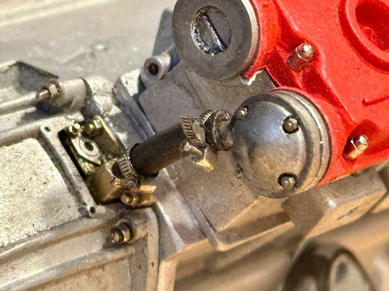
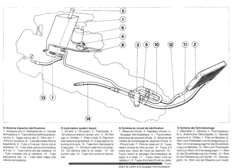
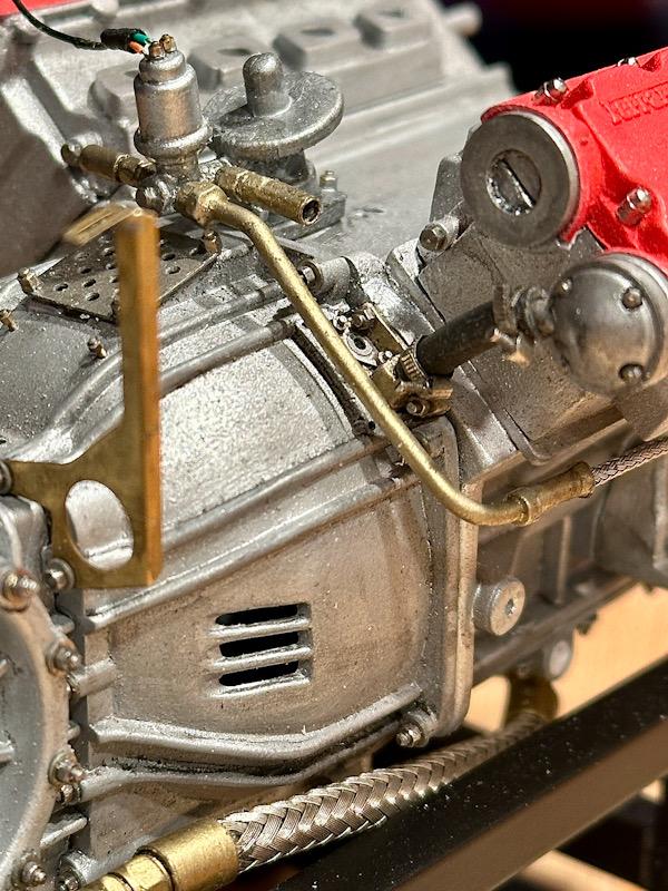
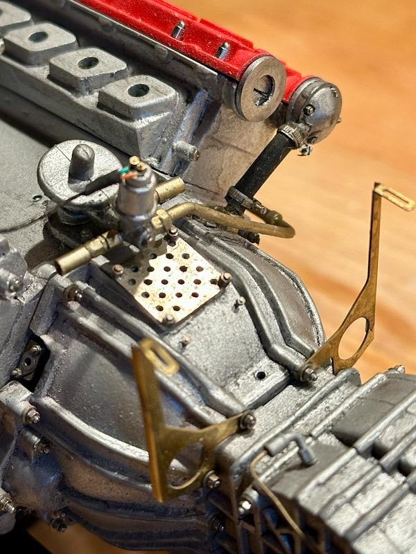
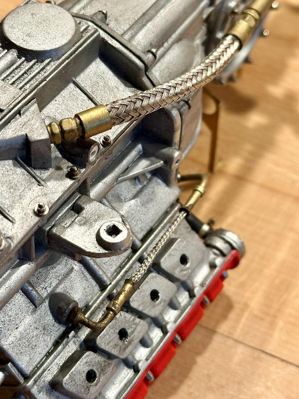
Next step is the cylinder head covers. In reality, these are powder-coated, giving them a rough surface. Therefore, I used Micro Balloons again, which I mixed into the paint. The color is Ferrari red from Vallejo. After painting, the covers were mounted. For screws, I use cap nuts from Autograph. Washers or brass sleeves were added in the area of the camshafts. I am more than satisfied with the surface of the cylinder head covers. There are covers on the two outer camshafts. These are from the Pocher kit but were detailed with screws and etched parts from the Autograph transkit. On the rear side of the crankcase, there is an end cover that is necessary for the oil circuit and also serves as a holder for the TDC sensors. This area is also exposed on the clutch housing. To replicate this detail, I rebuilt the visible area of the cover from ABS. The parts were then painted with Brass from True Metal Color and improved with screws and etched parts. Then the oil line was made, connecting the end cover and the right camshaft cover. The hose clamps are etched parts from the Autograph transkit, and the screws are small watchmaker's screws. Next, we continue with the housing on which the oil filter and the oil pressure sensor are installed. The part from the Pocher kit is quite basic. The connections for three oil lines are missing. In the Autograph transkit, there are white metal parts for the connection fittings. These were painted in brass and mounted. The oil pressure sensor was supplemented with the connection line. Additionally, the mounting screws at the base of the housing were added. The F40 features a dry sump lubrication system. The oil pump is in the oil pan, the oil tank is located at the front right next to the engine, and the oil cooler is at the very back right. Depending on the oil temperature, the oil circulates directly or, if the temperature gets too high, the thermostat valve switches and the oil flows through the cooler. Autograph has made the thermostat valve with its three connections as a nice white metal part. The same goes for the line that goes from the oil filter to the crankcase. What is new to me is the way the flexible oil lines are made. In reality, the flexible oil lines are covered with a metal mesh. For this, Autograph includes coaxial cables of different diameters in the transkit. When the outer insulation is removed, you have an almost perfect replica of the original lines. To make the line more flexible, the inner core is also removed and replaced with a flexible wire. The original's crimp sleeves are represented by brass ferrules. Then everything was installed. That's it for today. See you soon Your Ferrarifan
-
Thanks for the compliment! I always try to push my limits?
-
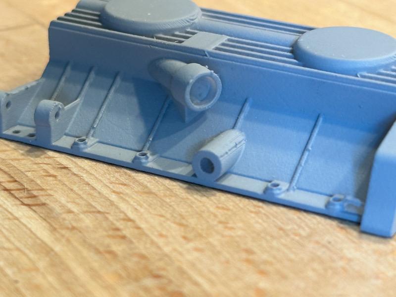
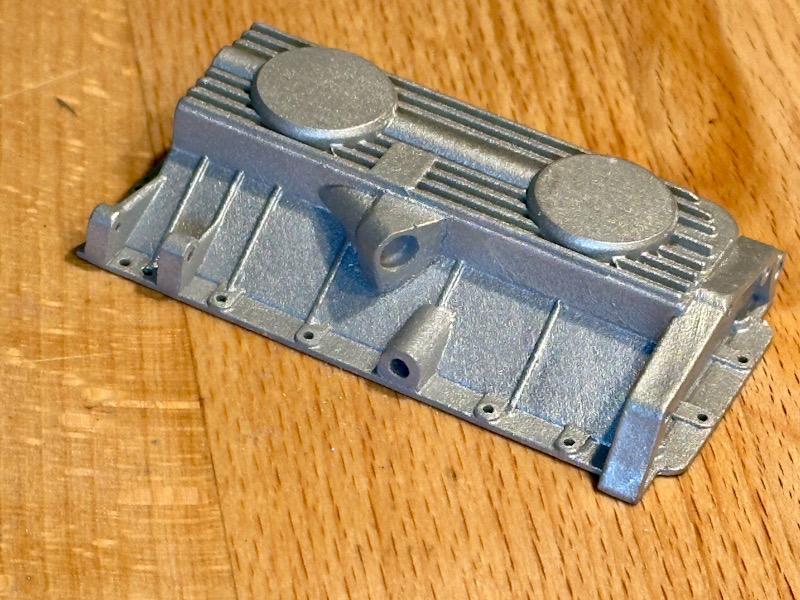
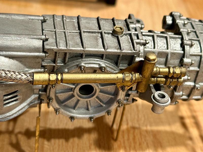
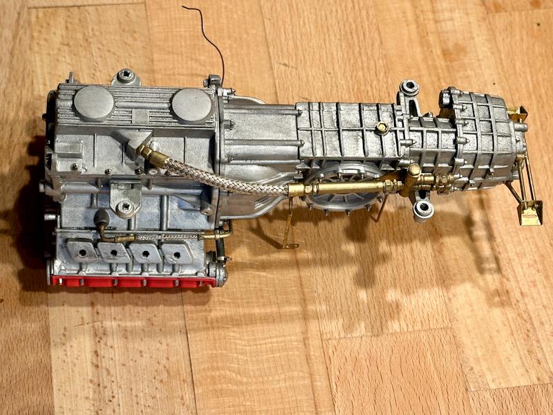
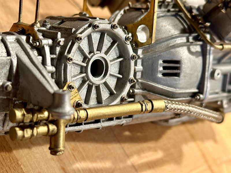
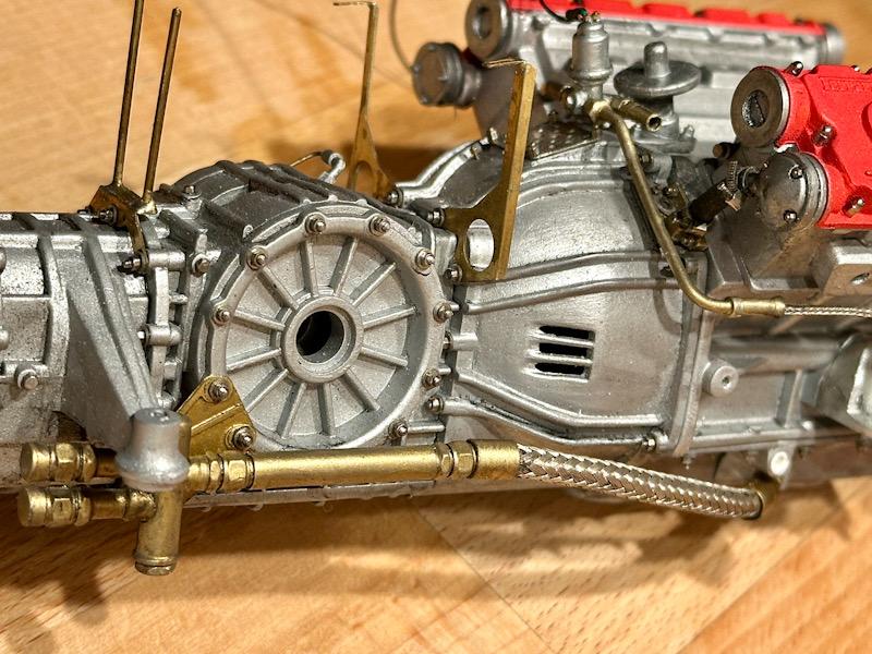
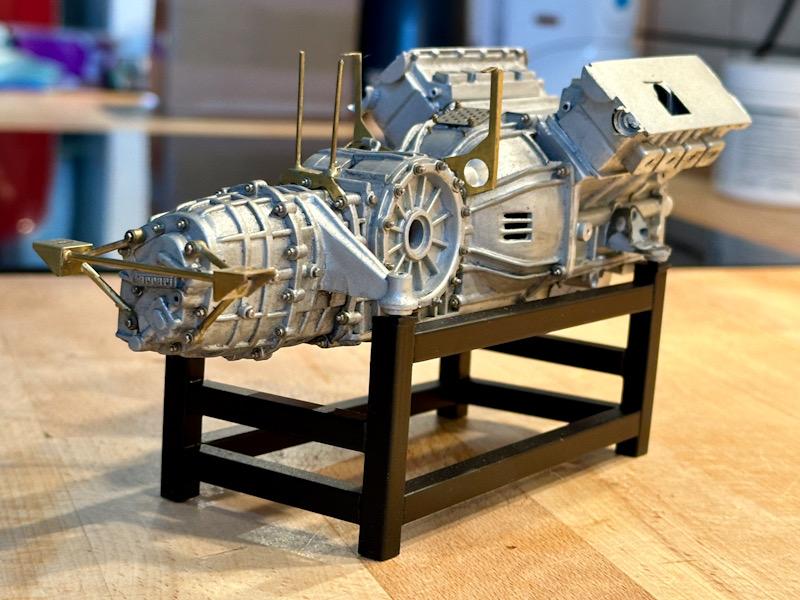
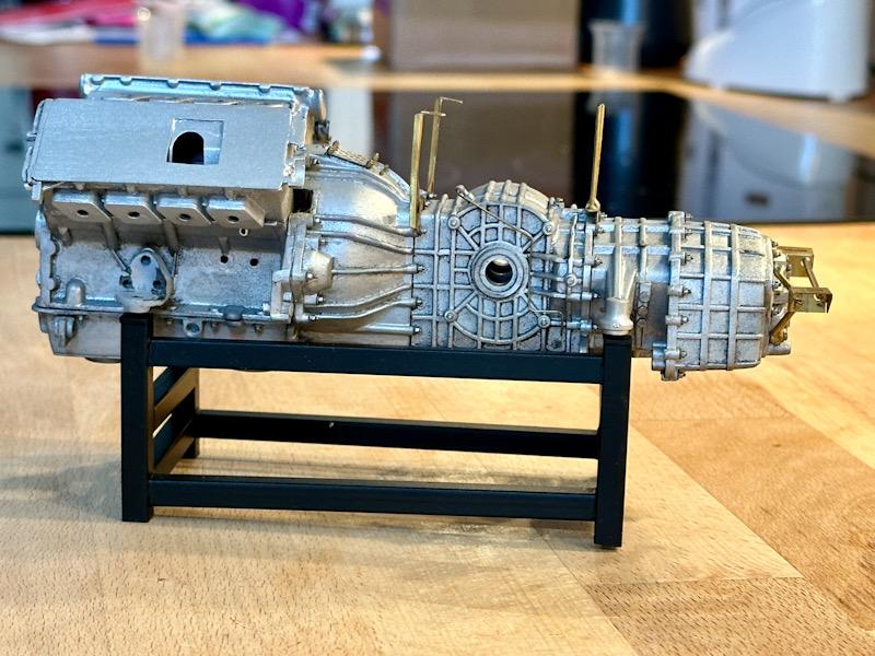
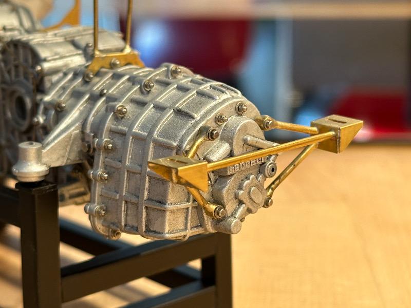
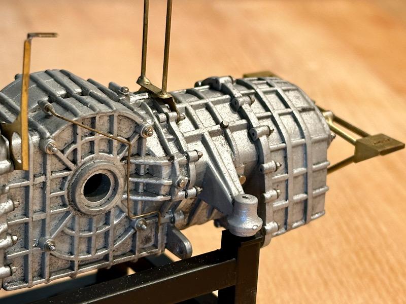
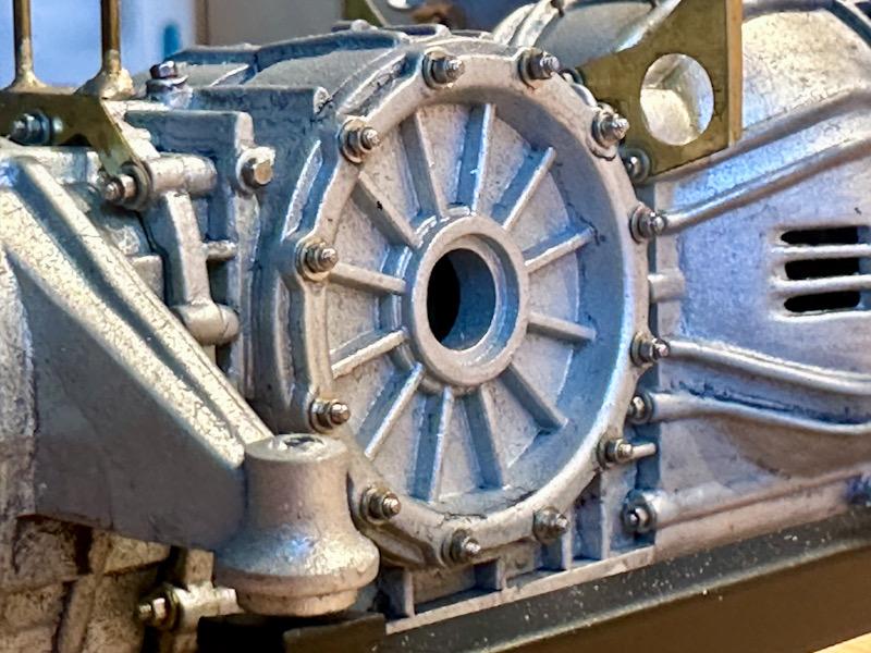
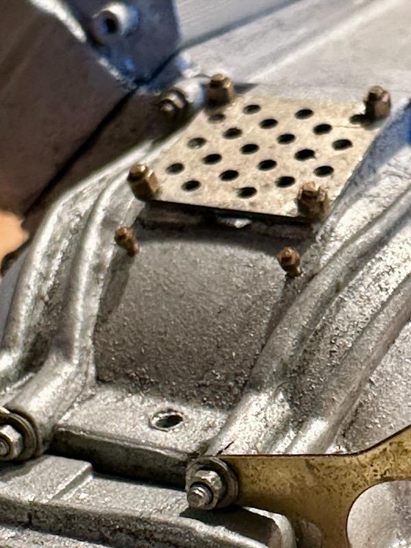
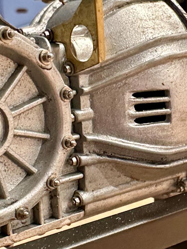
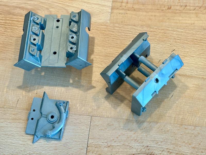
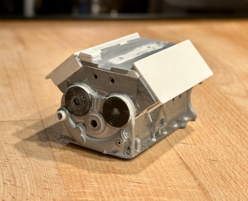
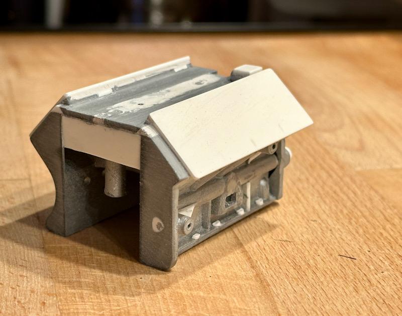
Before I start with the gearbox housing, the oil pan for the car's engine will be finished first. The connections for the oil lines on Pocher's oil pan are incorrect. Additionally, the screws are molded on. After the connections were redone and the screws removed, the oil pan was primed with Tamiya Primer. For the color, I used Aluminum from Vallejo's Acrylic Metal Color series. To achieve a cast-like surface, I used Micro Balloons, which I added to the paint by feel. When applying the paint with the airbrush, you can determine how strong the effect will be by applying it multiple times. I followed the same procedure for the crankcase. Next was the rear gearbox housing. Again, all molded screws were removed, and 0.8mm holes were drilled. Then the part was painted. The instructions from Autograph specify that M0.8 hex bolts should be used as replacements for the molded screw heads. However, the original has threaded studs, washers, and nuts. So, I clipped the heads off the hex bolts with pliers. Then I attached the nuts and washers to the newly made threaded studs with super glue. This allowed me to simply screw everything into the holes. In the rear section, four M0.8 nuts were glued into the holes of the muffler mount. The mount consists of brass bushings soldered with brass rods and etched parts. For this, the transkit includes a jig to solder the parts together precisely. Next, the clutch housing and the middle gearbox housing were made. The procedure was the same as for the rear gearbox housing. Then the individual components were assembled. Since I want to represent the engine in a used condition, an initial wash was done. Next, I made a frame from ABS profiles. This serves both to stabilize the engine during the next steps and will later be used for the standalone motor display. Afterward, the mounts for the intercoolers and the heat shield were installed. Here are a few detailed pictures showing the individual details nicely. That's it for today. See you soon, Your Ferrarifan
-
You are right! Even models in 1/64 are often more detailed? But on the other hand that’s what I like also. The worse the model is, the more I real modeling I can do.
-
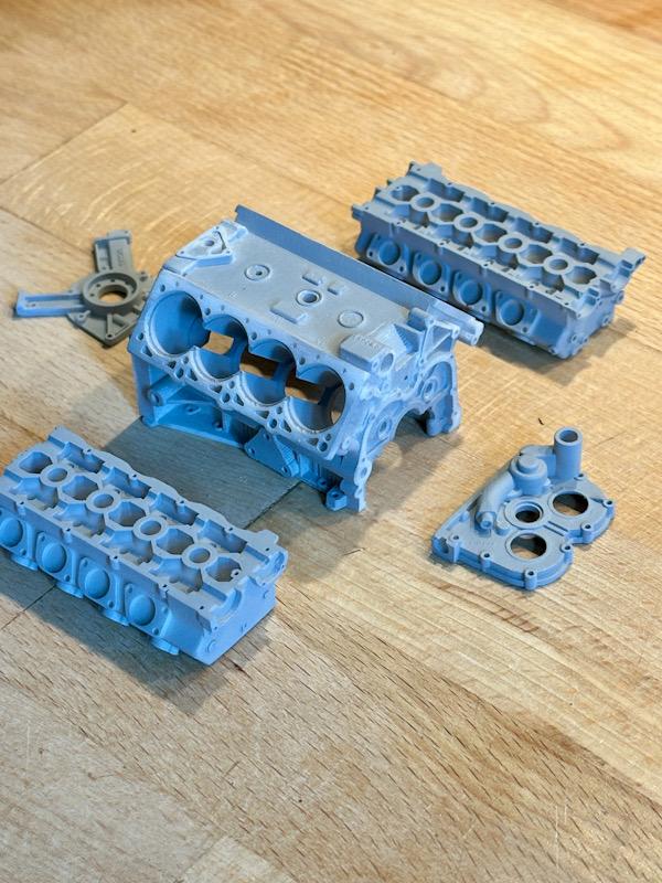
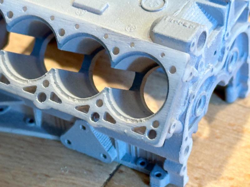
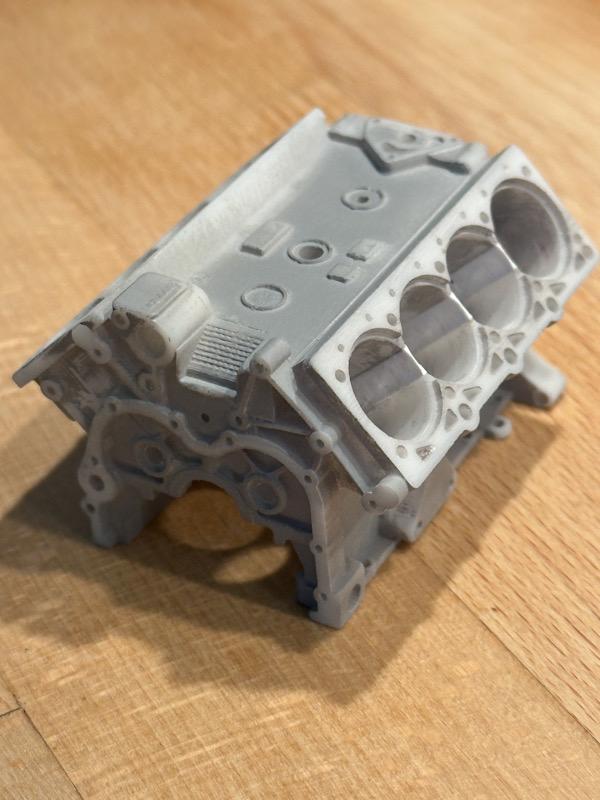
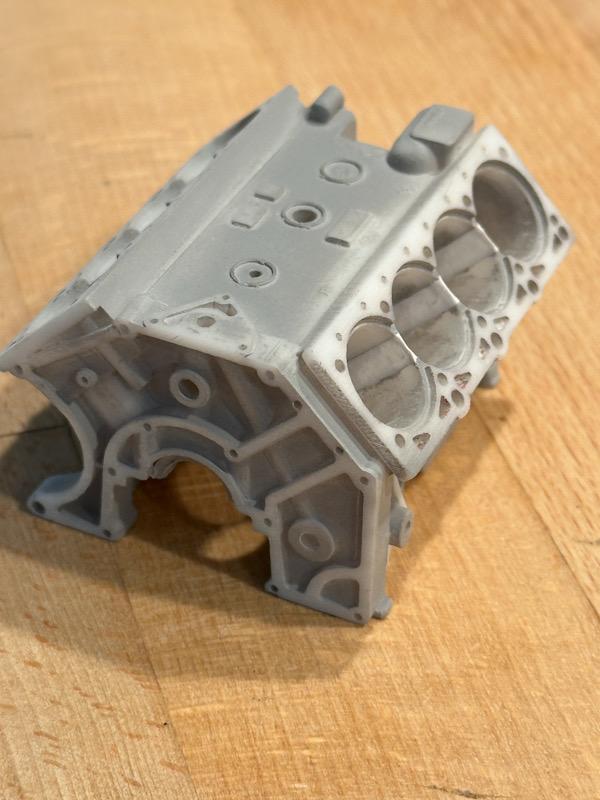
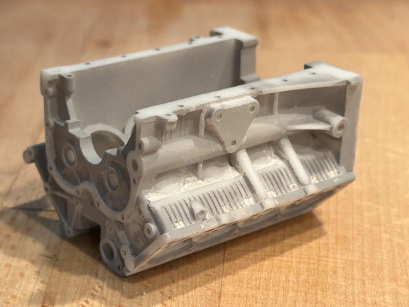
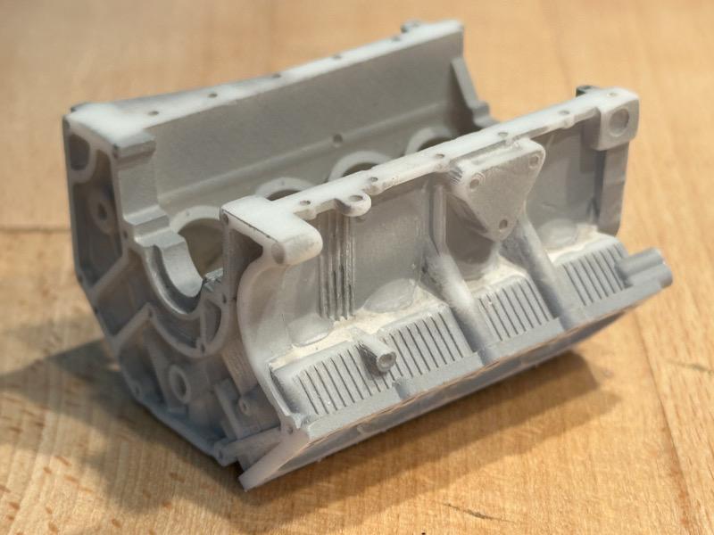
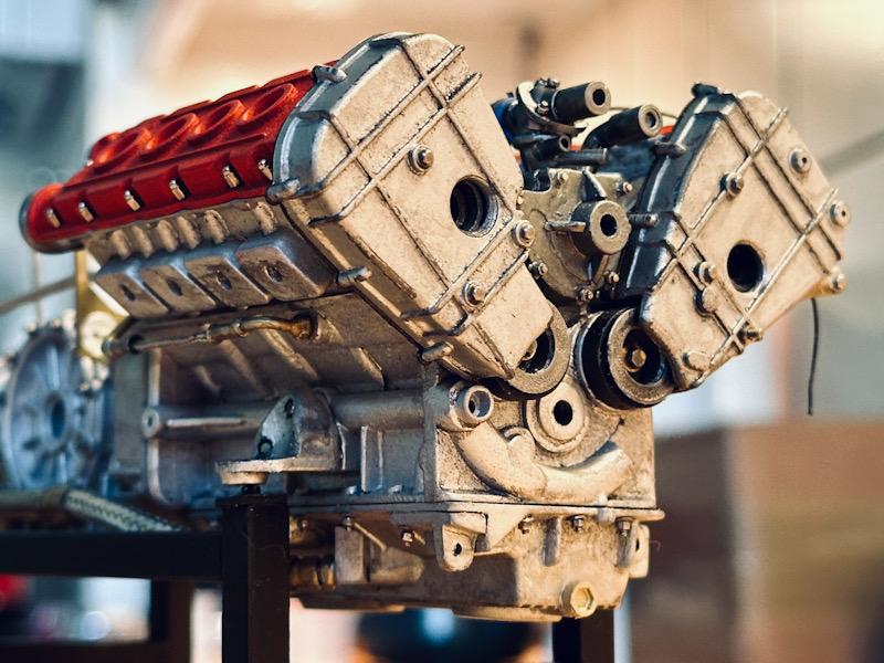
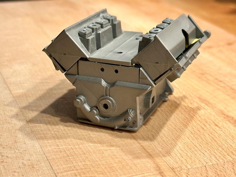
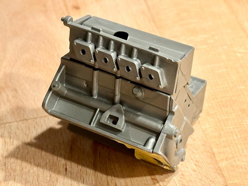
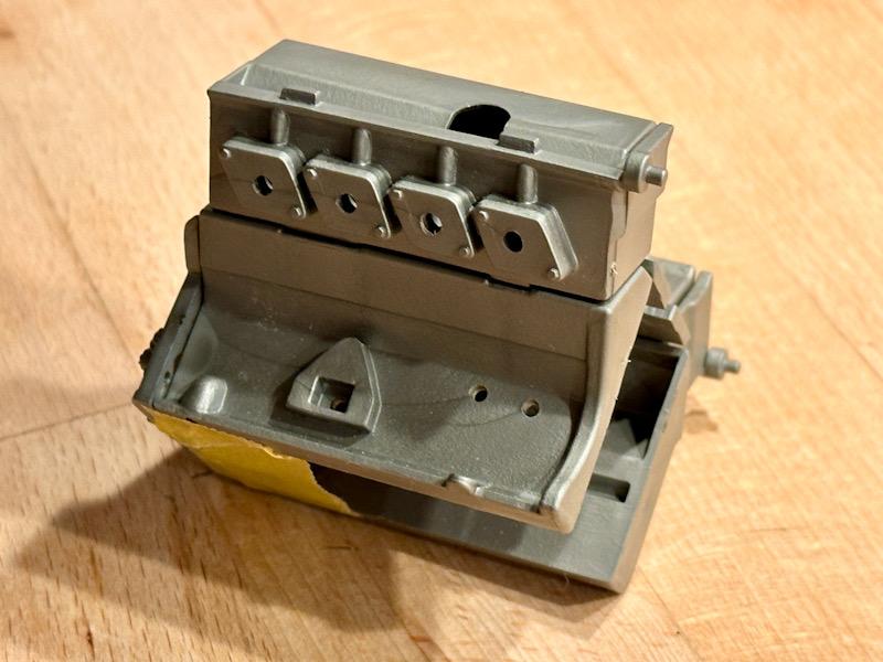
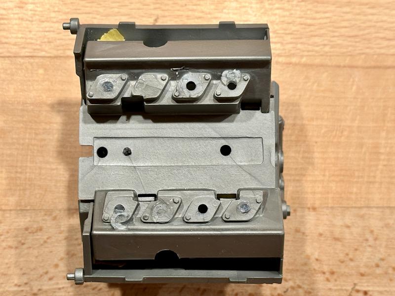
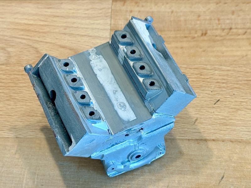
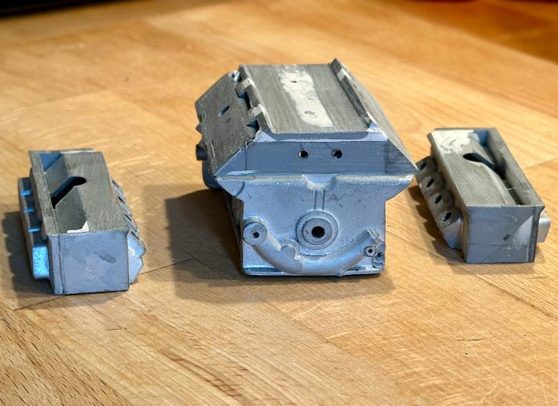
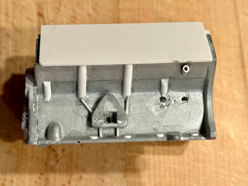
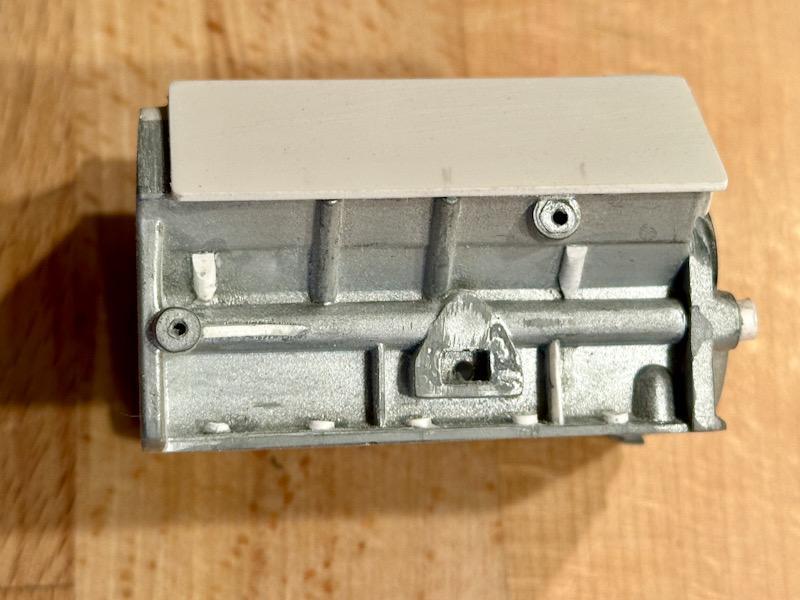
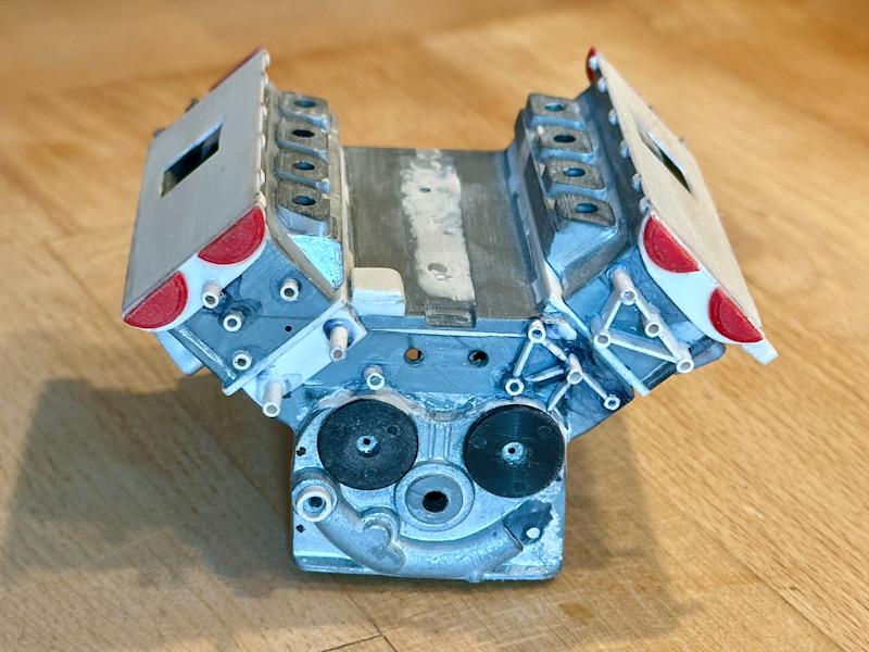
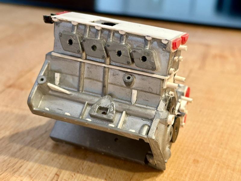
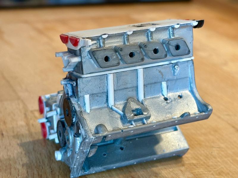
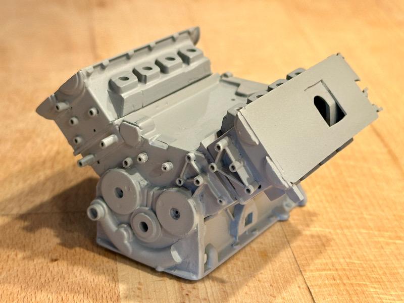
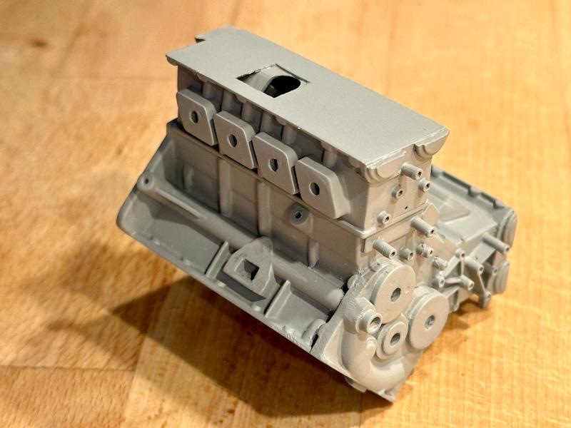
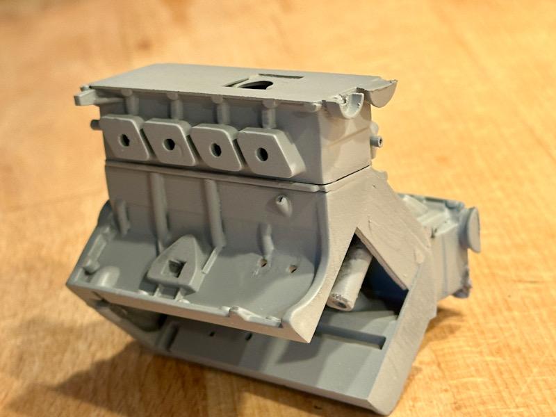
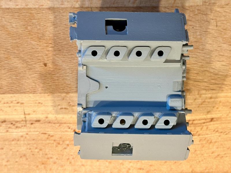
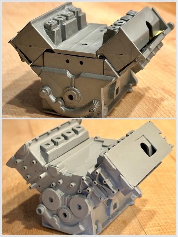
Today the work on the engine begins. As with the Testarossa, I will make 2 engines. A standalone model based on the Transkit by Tommaso Iuele. And the engine that will be installed in the car. This engine is based on the Pocher model and will be supplemented with parts from the Autograph Transkit and parts from Leadfoot Models. To ensure this engine is as close to the original as possible, I will make many additional changes and add details. I started with the engine block that will be installed in the car. The engine block consists of several parts, including the cylinder heads. The parts were glued together. As shown in the following pictures, the basic features of the original are depicted. However, many details are missing. First, I adjusted the area of the intake flanges on the cylinder heads. Molded screws were removed, and cavities were filled. Additionally, all gaps in the adhesive areas were filled with putty. The top surface of the engine block was also filled. Then, I cut off the cylinder heads with a fine saw. Next, the engine block was supplemented with ABS parts. The surface to the cylinder heads was doubled with a 1mm plate. The shape in the area of the belt drive was adjusted. Furthermore, missing oil and water channels and screw connections to the oil pan were added to the sides. Then the cylinder heads were mounted, and the missing screw connections and ribs in the area of the belt drive were added. Additionally, the surface to the valve covers was doubled, screw connections to the valve covers and the lower half of the bearing shells for the camshafts were added. The bearing shells were previously separated from the valve covers. Then everything was primed. In a direct before-and-after comparison, you can see what can be done with a little patience to improve the engine block. That's it for today. Next, the transmission for this engine will be made. See you soon Your Ferrarifan