Ferrarifan
-
Posts
31 -
Joined
-
Last visited
Content Type
Profiles
Forums
Events
Gallery
Everything posted by Ferrarifan
-
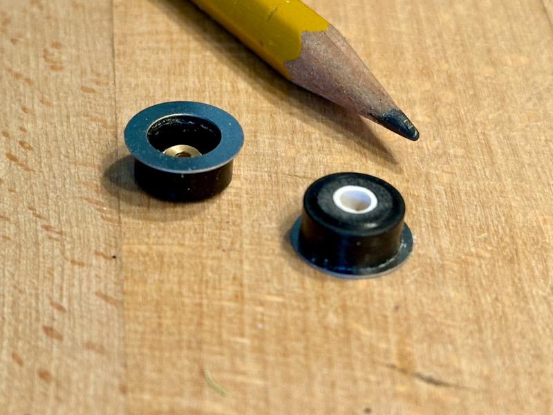
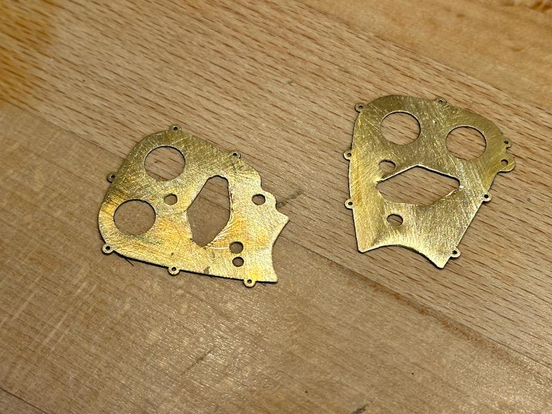
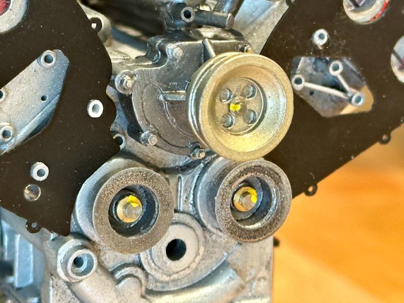
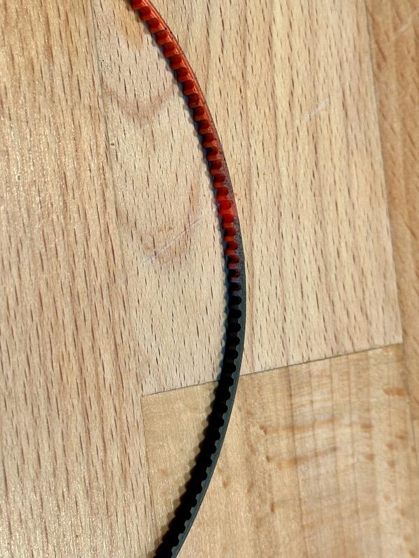
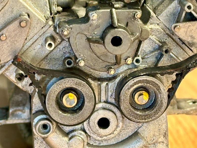
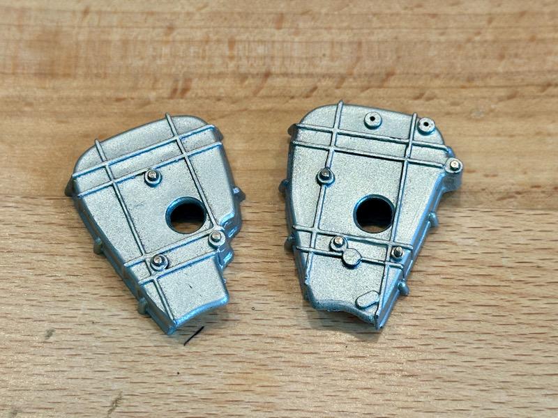
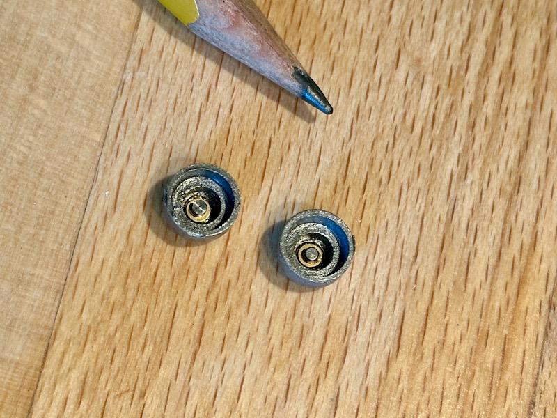
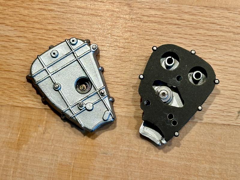
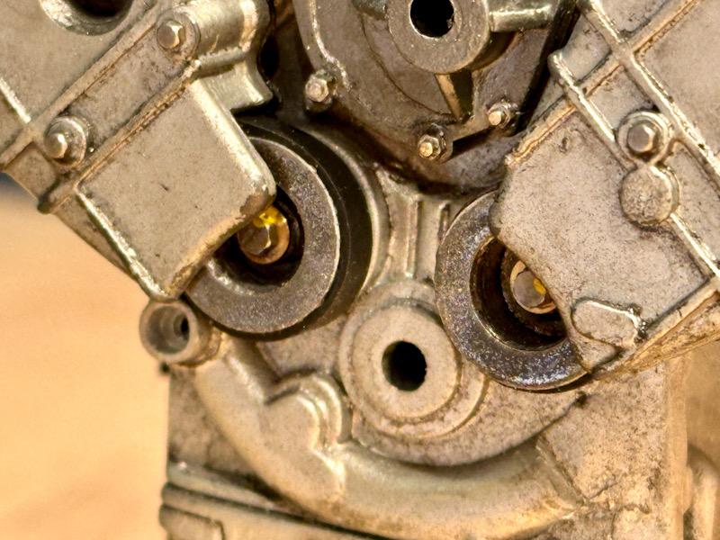
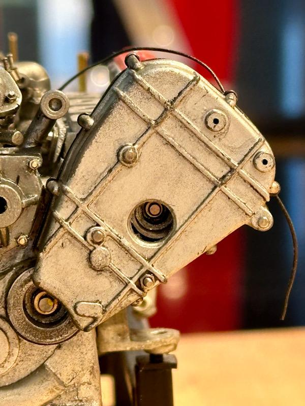
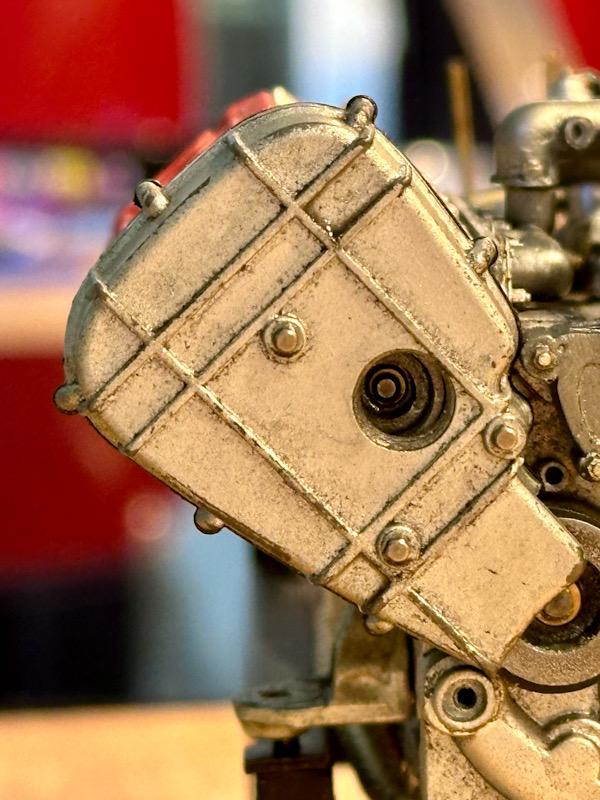
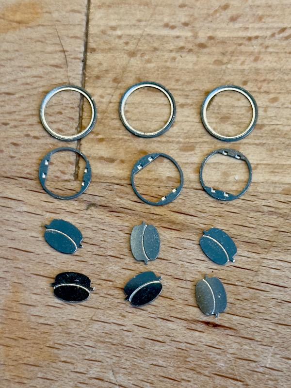
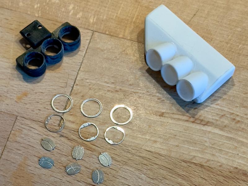
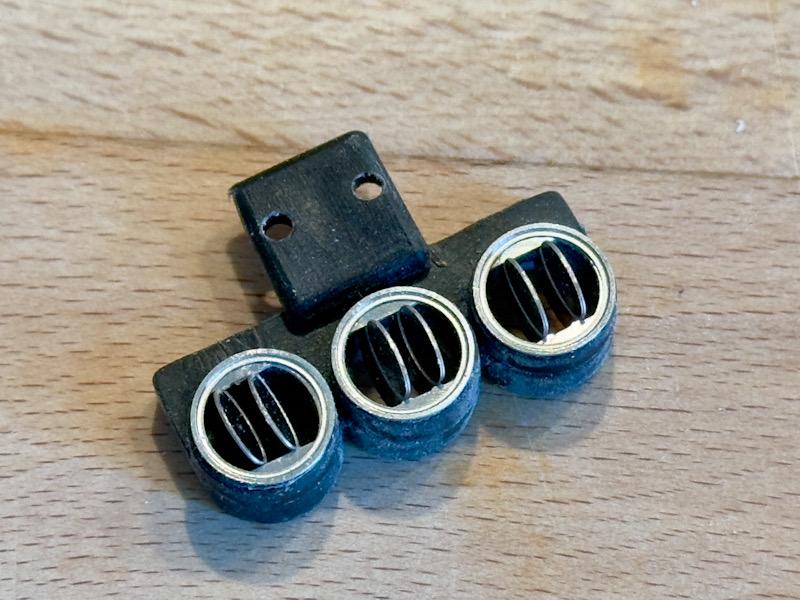
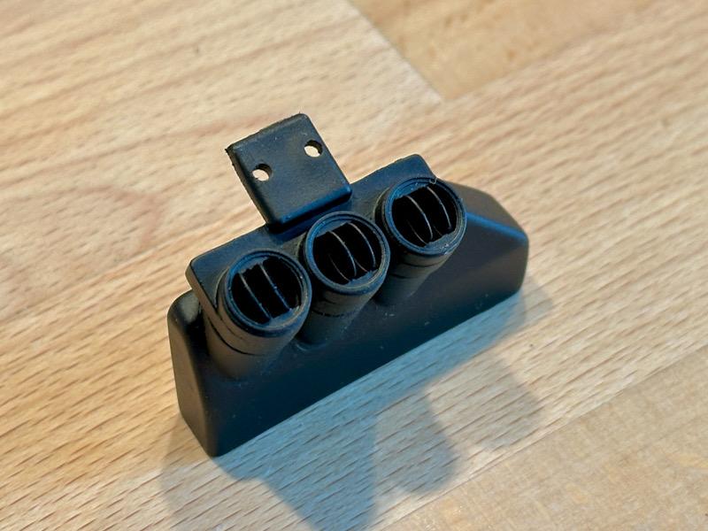
As previously announced, today it's the turn of the timing belt drive of the camshafts. Since the two lower pulleys are missing in the Pocher model, I made simplified pulleys from "leftovers" from the Testarossa. They were then painted with Vallejo Steel and glued on. To protect the timing belt as much as possible, there are cover plates on the back of the belt drive. Autograph made etched parts for this. Since I added the mounting bosses for the timing belt cover and the tension rollers to the crankcase and cylinder heads, the etched parts had to be adjusted accordingly. Additional holes were drilled in the area of the bosses, and the area where the tension rollers are mounted was also cut out. Furthermore, the lower area was cleared to mount the pulleys. Then the plates were primed and painted black. Here is a picture of the trial assembly. Even though this area will no longer be visible after the engine is installed, I decided to depict the outer area of the timing belt. As with the Testarossa, the timing belt from a microwave is used. This was painted black and glued to the pulleys. The timing belt covers were slightly modified. Molded screw heads were removed and replaced with real screws. In the area of the tension rollers, there is an opening in the original. Since this was missing in the Pocher part, the area was drilled out. The lower area on the back was cut out for the timing belt, as in the original. The tension rollers were also made from leftovers from the Testarossa. Then the rear cover plates and the tension rollers were mounted on the covers. Finally, the assembled covers were mounted on the housing and the area was given a stronger wash. To conclude, here are a few detail pictures of this area. That's it for today. See you soon, Your Ferrari fan

-
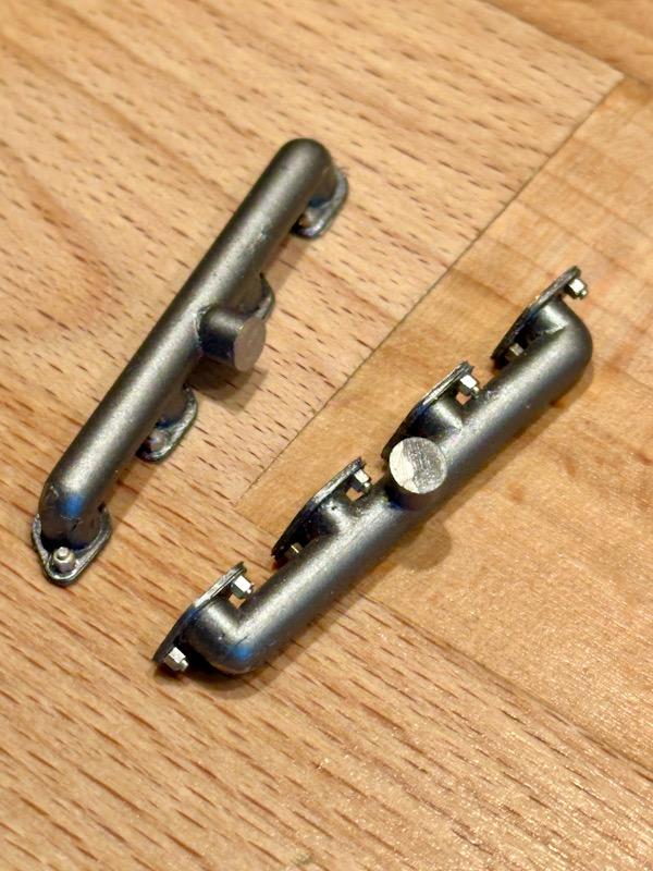
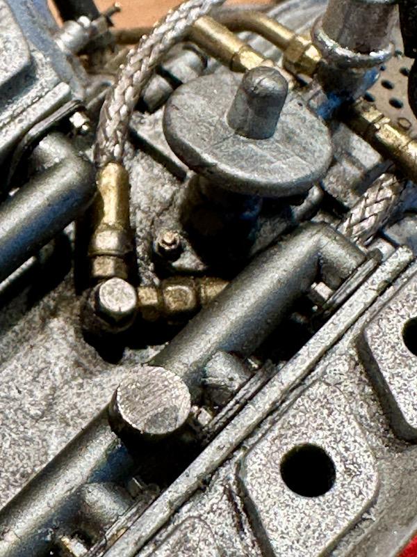
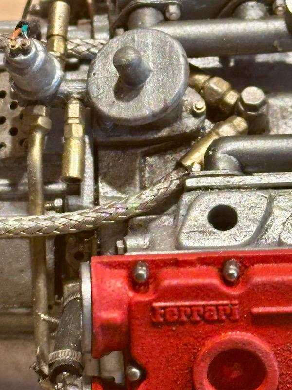
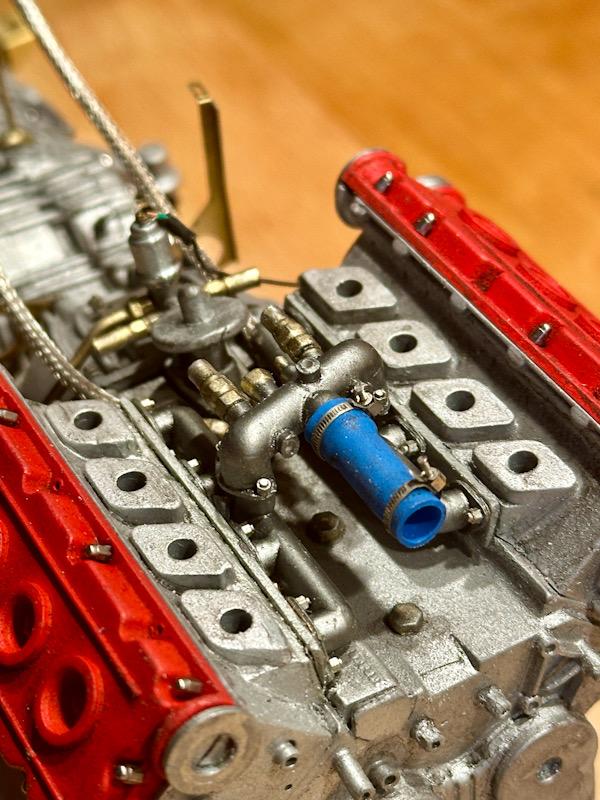
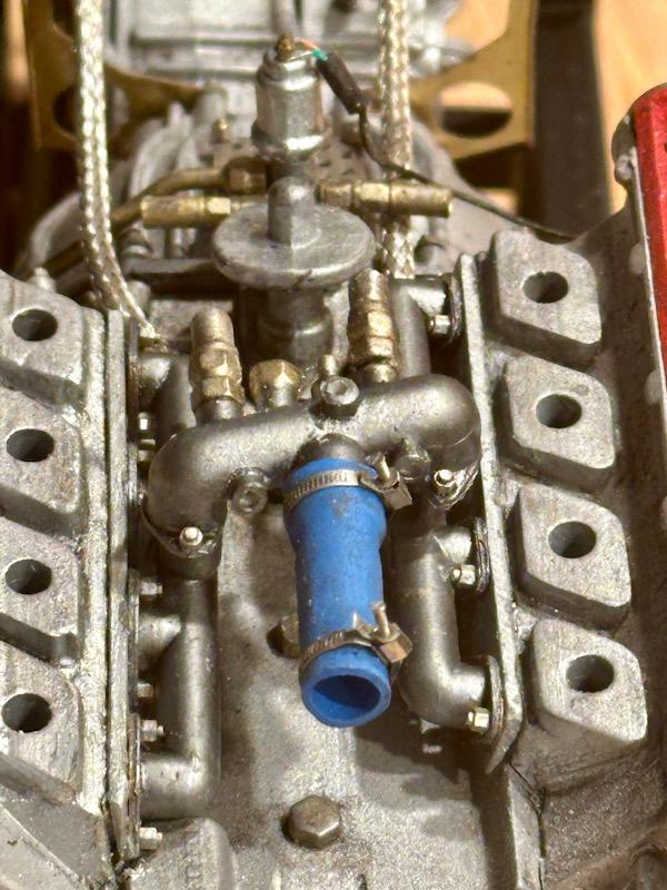
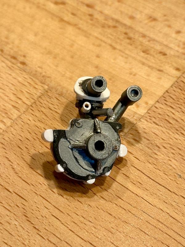
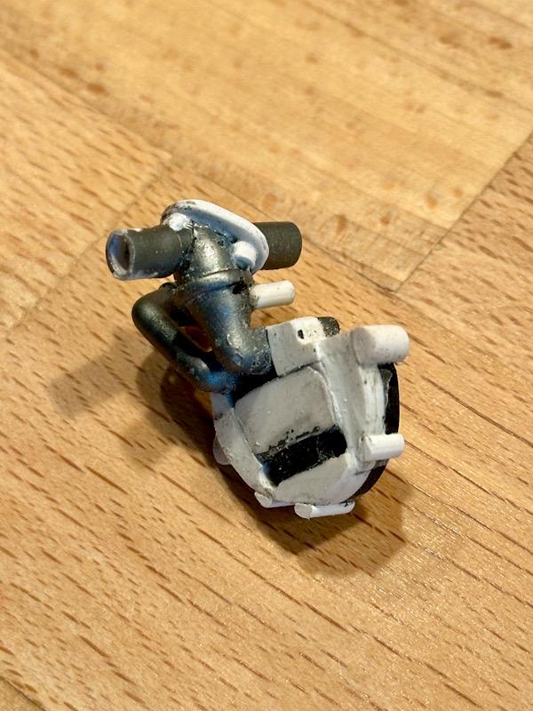
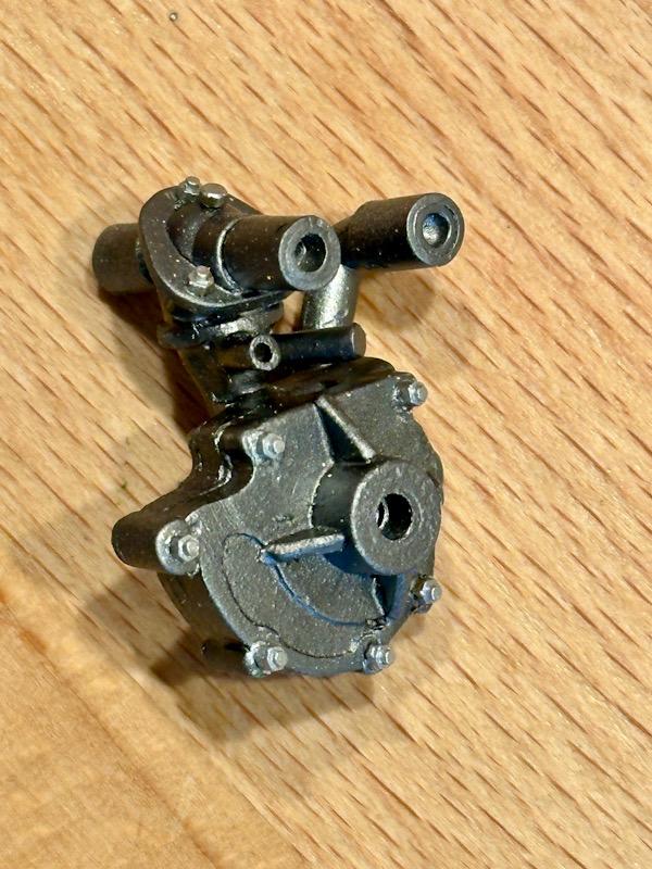
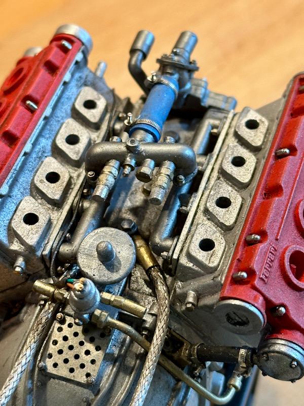
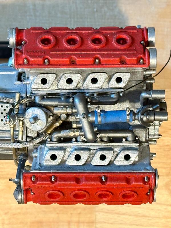
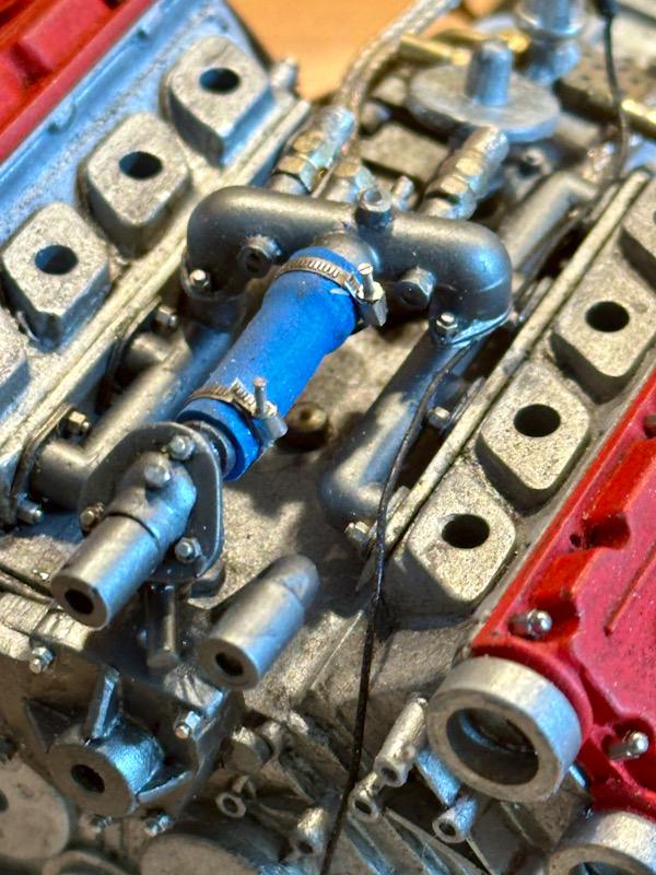
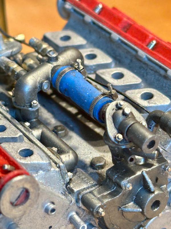
Today I start with the cooling system for the engine and the two turbos. The Autograph transkit includes nice white metal parts for this purpose. The first part to be made is the T-piece for the turbochargers. As with the oil lines, coaxial cables and ferrules are used for the lines. Next were the two collectors, which are mounted on the sides of the cylinder heads. For this, the transkit includes white metal and etched parts. After gluing the parts together, they were primed and painted in gunmetal. For screws, I used copper imitations from Knupfer, which were then colored with True Metal Steel. Subsequently, the parts were installed and given a light wash. The next step was the bridge that connects the two collectors. The return lines from the turbochargers are also connected here. The main line then goes forward to the water pump. The main part is again made of white metal. The main line is made from a shrink tube. For the hose clamps, Autograph provides nice etched parts and fine watchmaker screws. The bridge was then attached to the two collectors using super glue. Next up was the water pump. To ensure the water pump fits snugly against the crankcase, the back was doubled up. The housing is split at the top, where the thermostat is installed. I sawed apart the injection-molded part and added a screw flange. Then the missing inlet and outlet pipes and screw plugs were added. After the pump was painted, the missing screws were added. Then the water pump was mounted. So that's the current state of construction. Next time, the timing belt and the associated drive gears, tensioners, and covers are up. See you soon, Your Ferrari fan
-
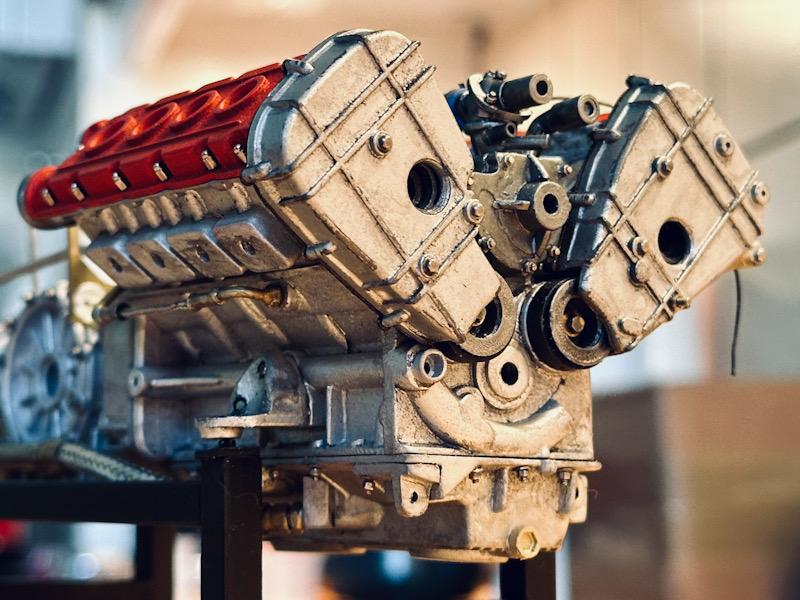
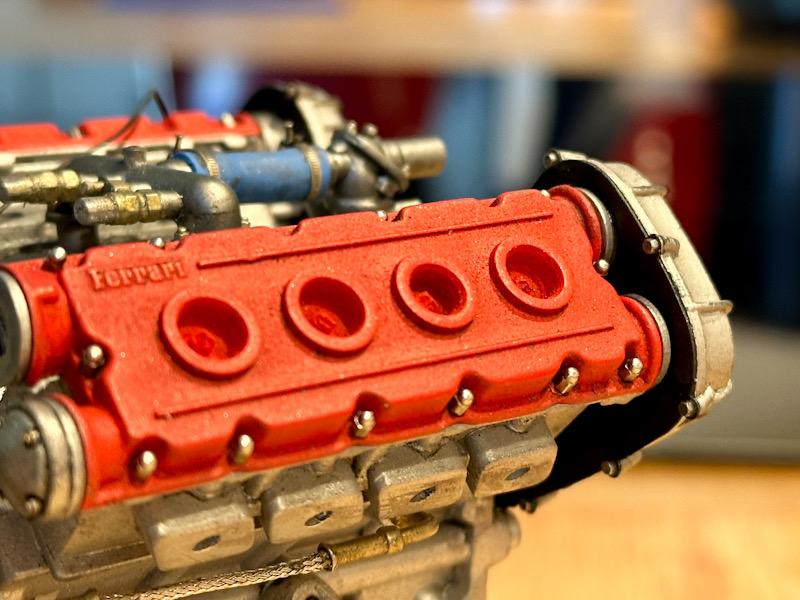
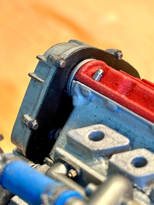
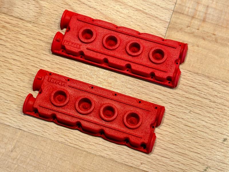
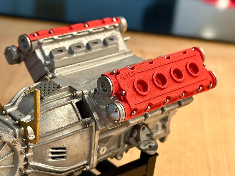
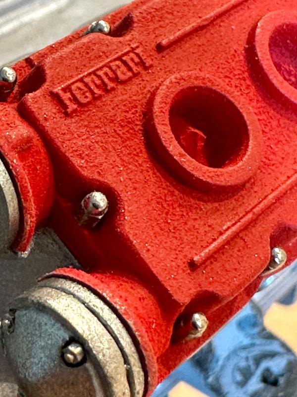
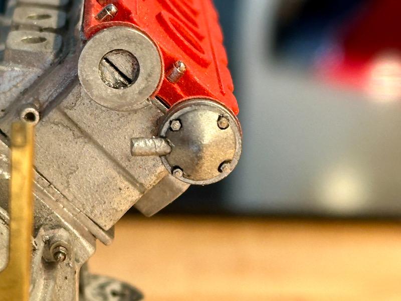
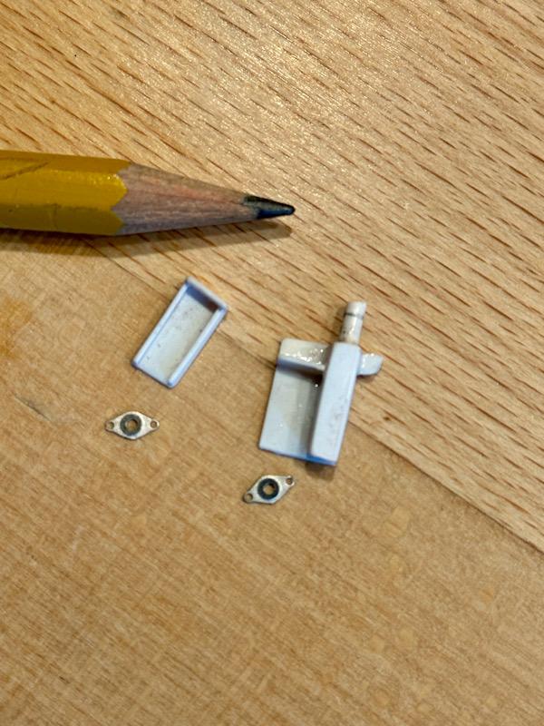
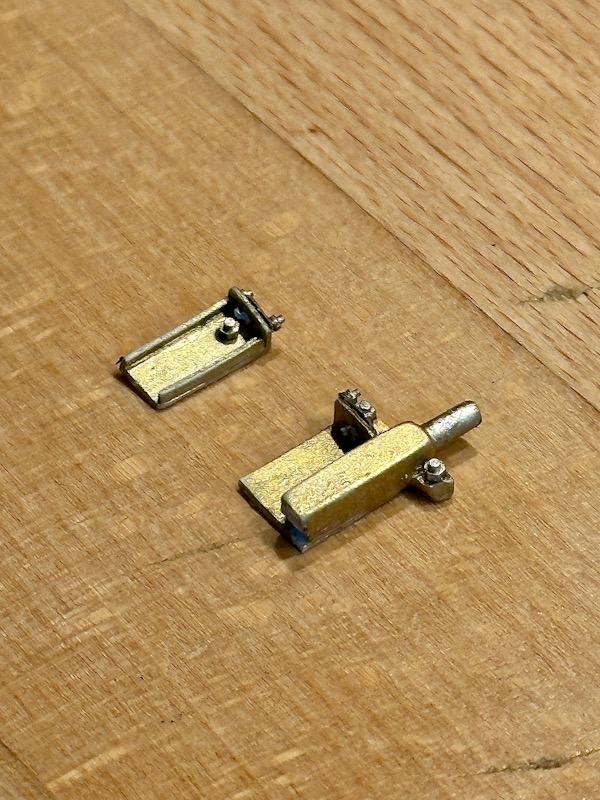
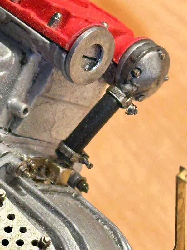
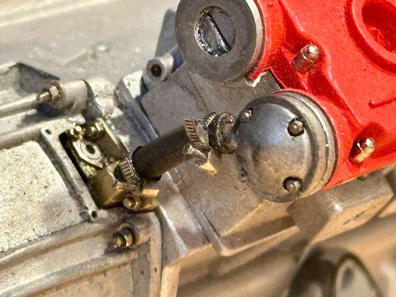
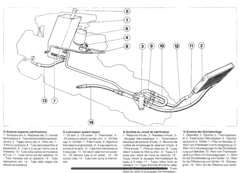
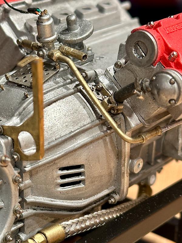
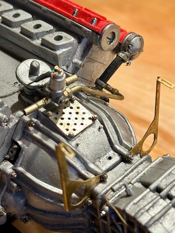
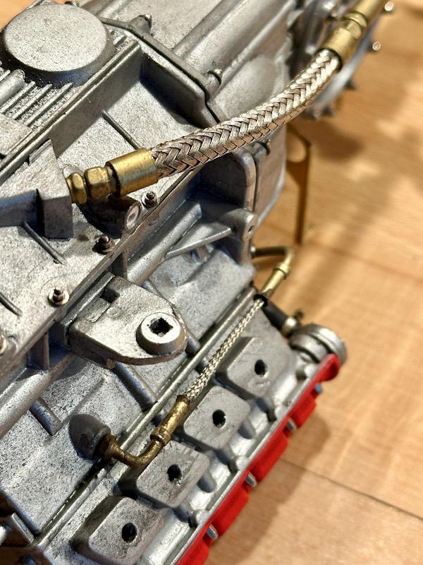
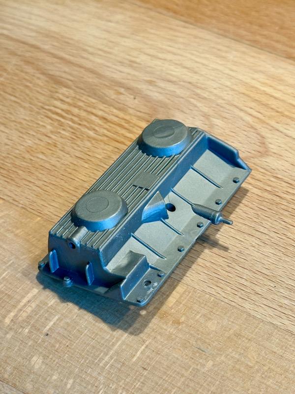
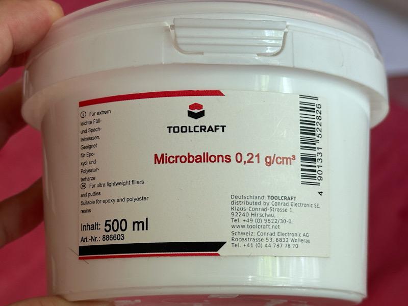
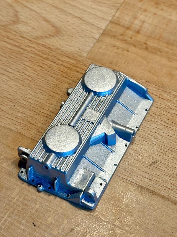
Next step is the cylinder head covers. In reality, these are powder-coated, giving them a rough surface. Therefore, I used Micro Balloons again, which I mixed into the paint. The color is Ferrari red from Vallejo. After painting, the covers were mounted. For screws, I use cap nuts from Autograph. Washers or brass sleeves were added in the area of the camshafts. I am more than satisfied with the surface of the cylinder head covers. There are covers on the two outer camshafts. These are from the Pocher kit but were detailed with screws and etched parts from the Autograph transkit. On the rear side of the crankcase, there is an end cover that is necessary for the oil circuit and also serves as a holder for the TDC sensors. This area is also exposed on the clutch housing. To replicate this detail, I rebuilt the visible area of the cover from ABS. The parts were then painted with Brass from True Metal Color and improved with screws and etched parts. Then the oil line was made, connecting the end cover and the right camshaft cover. The hose clamps are etched parts from the Autograph transkit, and the screws are small watchmaker's screws. Next, we continue with the housing on which the oil filter and the oil pressure sensor are installed. The part from the Pocher kit is quite basic. The connections for three oil lines are missing. In the Autograph transkit, there are white metal parts for the connection fittings. These were painted in brass and mounted. The oil pressure sensor was supplemented with the connection line. Additionally, the mounting screws at the base of the housing were added. The F40 features a dry sump lubrication system. The oil pump is in the oil pan, the oil tank is located at the front right next to the engine, and the oil cooler is at the very back right. Depending on the oil temperature, the oil circulates directly or, if the temperature gets too high, the thermostat valve switches and the oil flows through the cooler. Autograph has made the thermostat valve with its three connections as a nice white metal part. The same goes for the line that goes from the oil filter to the crankcase. What is new to me is the way the flexible oil lines are made. In reality, the flexible oil lines are covered with a metal mesh. For this, Autograph includes coaxial cables of different diameters in the transkit. When the outer insulation is removed, you have an almost perfect replica of the original lines. To make the line more flexible, the inner core is also removed and replaced with a flexible wire. The original's crimp sleeves are represented by brass ferrules. Then everything was installed. That's it for today. See you soon Your Ferrarifan
-
Thanks for the compliment! I always try to push my limits😁
-
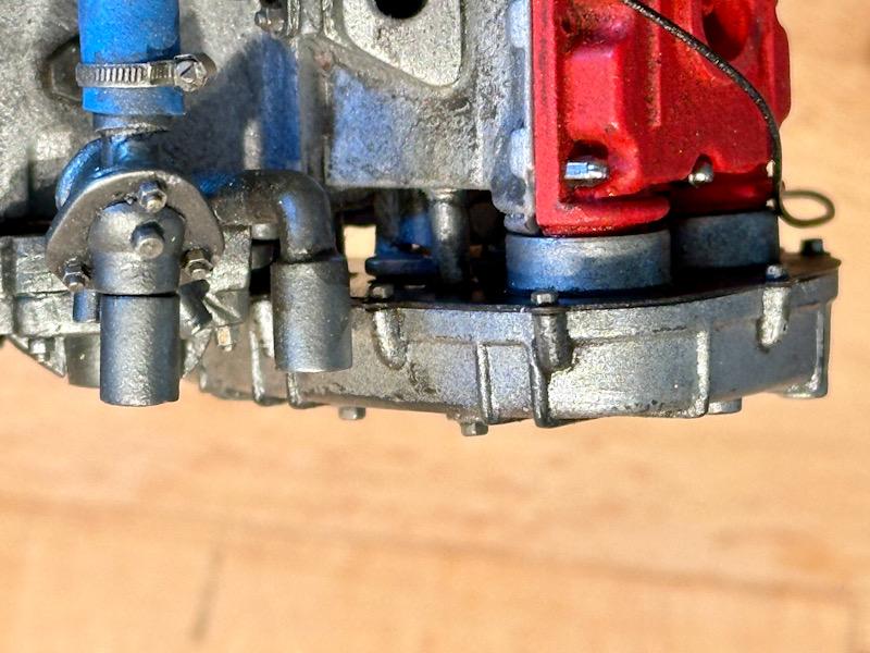
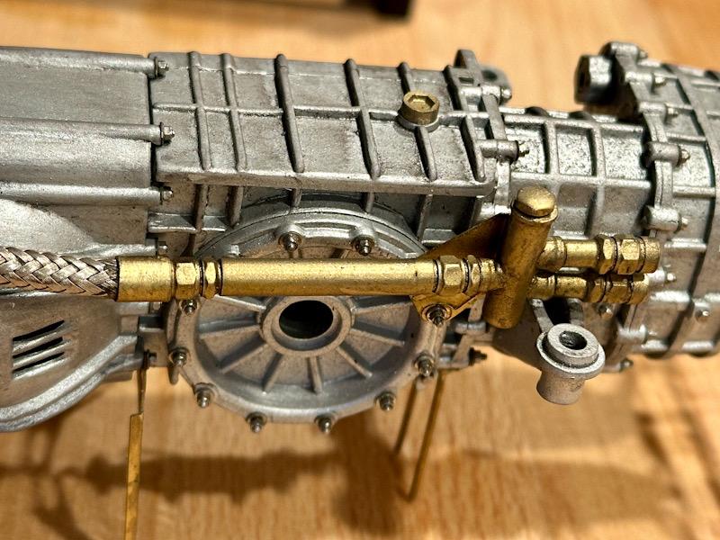
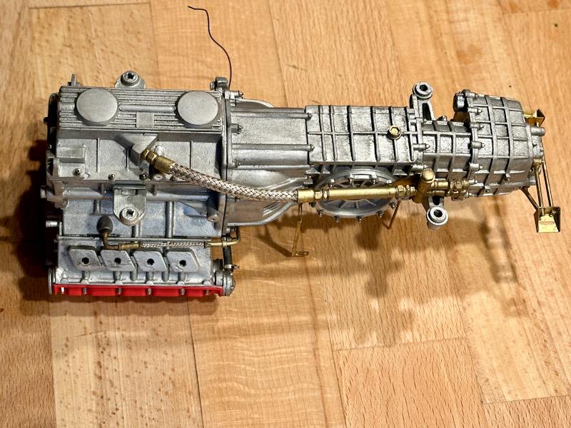
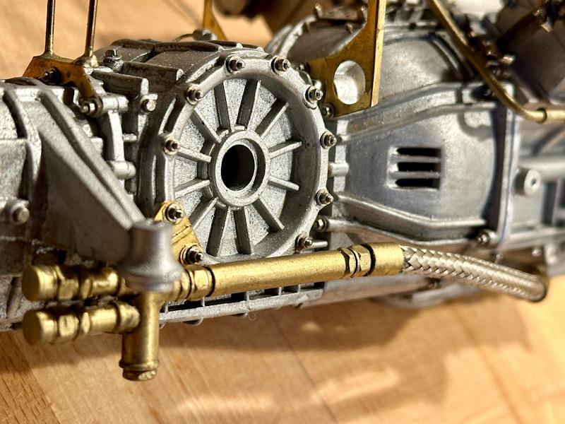
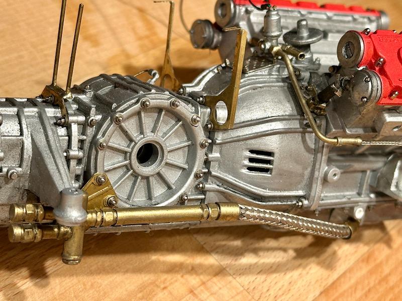
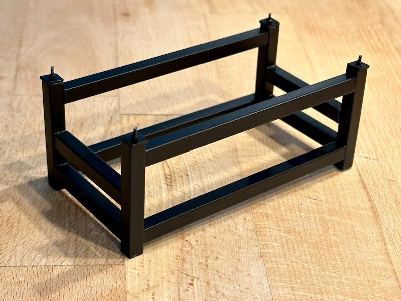
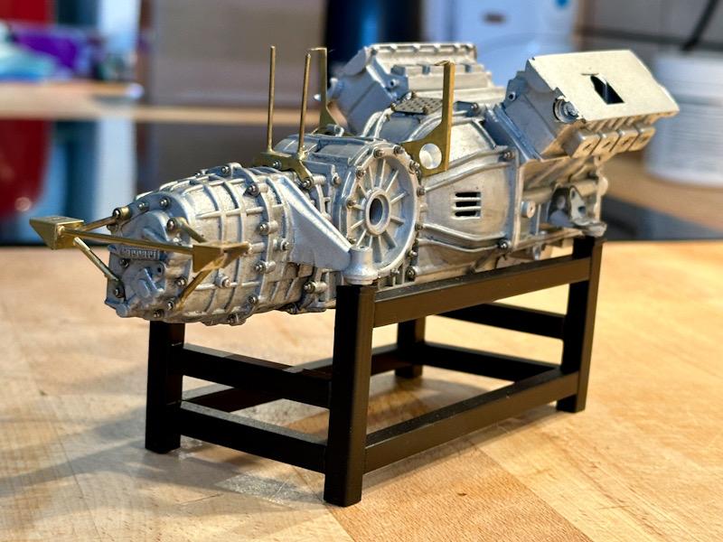
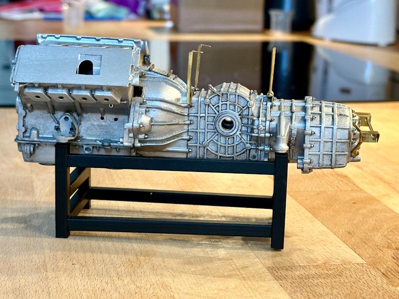
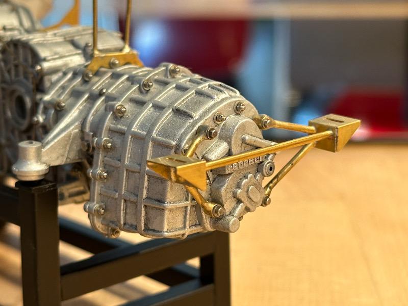
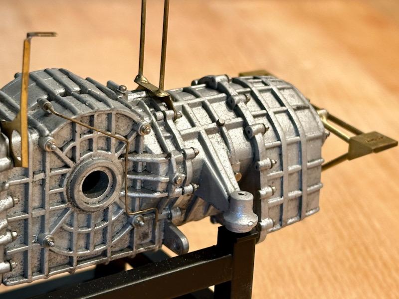
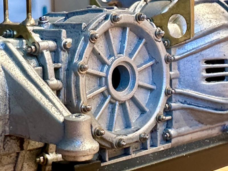
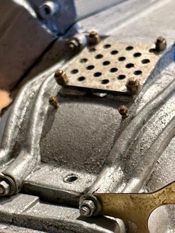
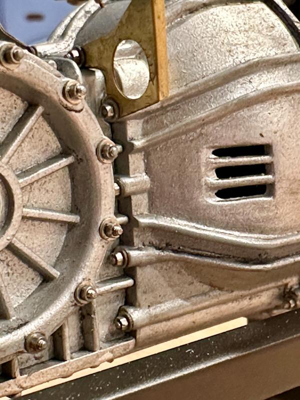
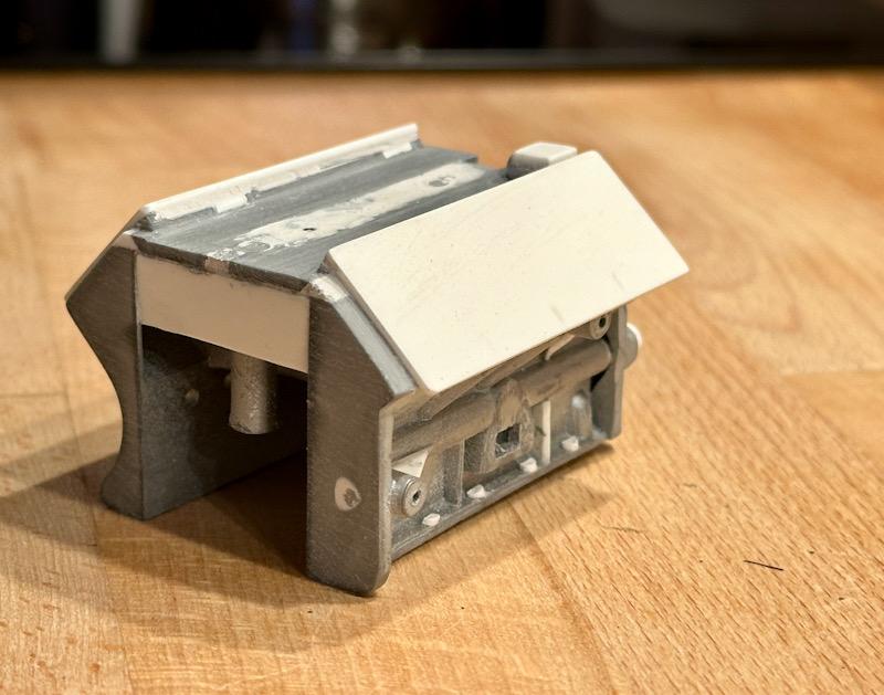
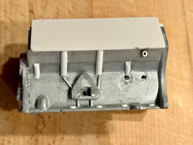
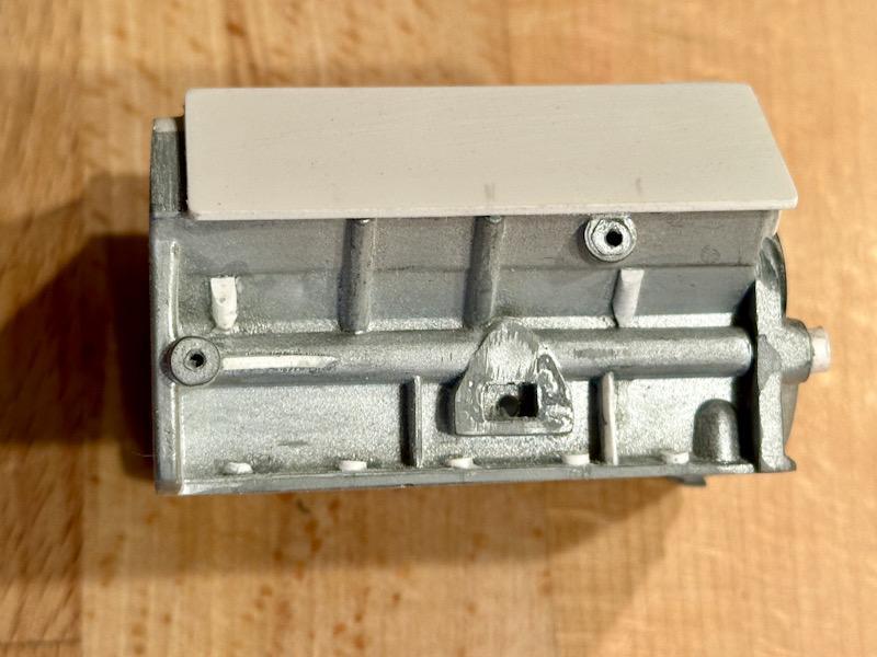
Before I start with the gearbox housing, the oil pan for the car's engine will be finished first. The connections for the oil lines on Pocher's oil pan are incorrect. Additionally, the screws are molded on. After the connections were redone and the screws removed, the oil pan was primed with Tamiya Primer. For the color, I used Aluminum from Vallejo's Acrylic Metal Color series. To achieve a cast-like surface, I used Micro Balloons, which I added to the paint by feel. When applying the paint with the airbrush, you can determine how strong the effect will be by applying it multiple times. I followed the same procedure for the crankcase. Next was the rear gearbox housing. Again, all molded screws were removed, and 0.8mm holes were drilled. Then the part was painted. The instructions from Autograph specify that M0.8 hex bolts should be used as replacements for the molded screw heads. However, the original has threaded studs, washers, and nuts. So, I clipped the heads off the hex bolts with pliers. Then I attached the nuts and washers to the newly made threaded studs with super glue. This allowed me to simply screw everything into the holes. In the rear section, four M0.8 nuts were glued into the holes of the muffler mount. The mount consists of brass bushings soldered with brass rods and etched parts. For this, the transkit includes a jig to solder the parts together precisely. Next, the clutch housing and the middle gearbox housing were made. The procedure was the same as for the rear gearbox housing. Then the individual components were assembled. Since I want to represent the engine in a used condition, an initial wash was done. Next, I made a frame from ABS profiles. This serves both to stabilize the engine during the next steps and will later be used for the standalone motor display. Afterward, the mounts for the intercoolers and the heat shield were installed. Here are a few detailed pictures showing the individual details nicely. That's it for today. See you soon, Your Ferrarifan
-
You are right! Even models in 1/64 are often more detailed🥴 But on the other hand that’s what I like also. The worse the model is, the more I real modeling I can do.
-
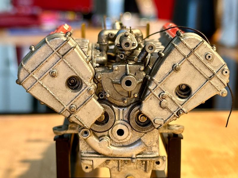
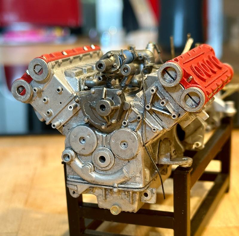
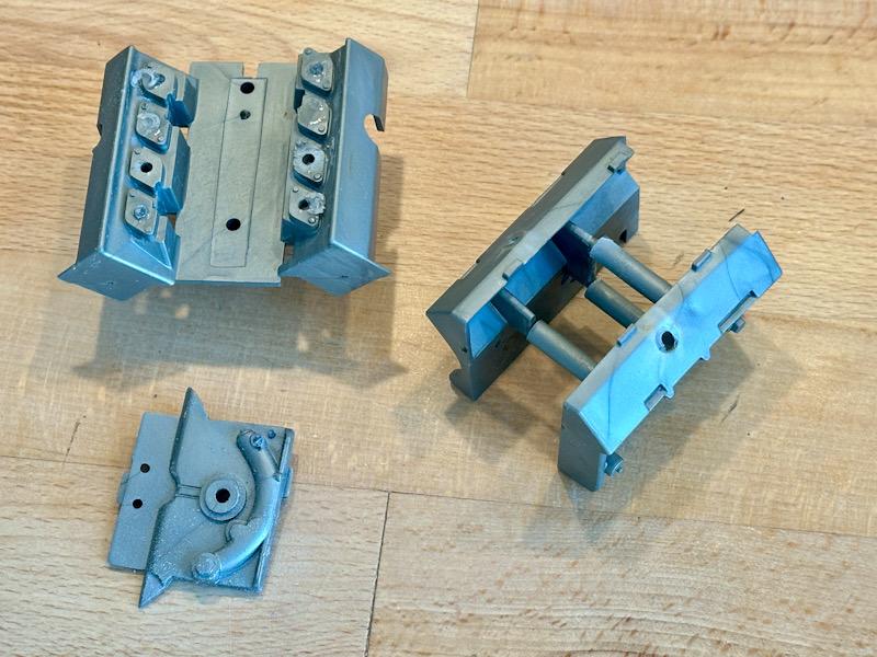
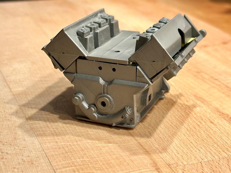
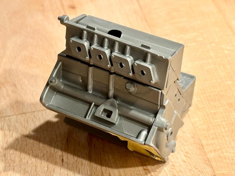
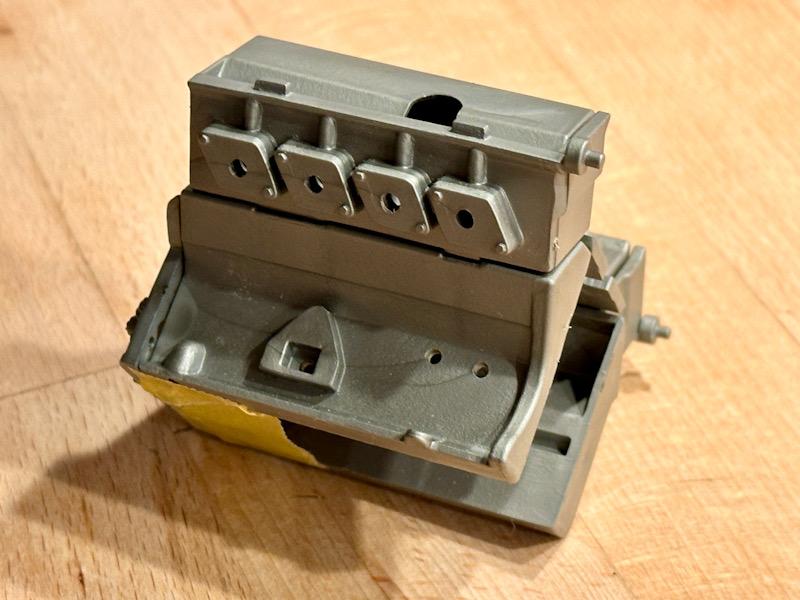
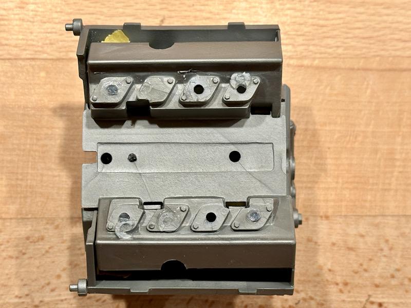
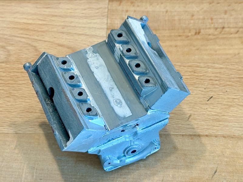
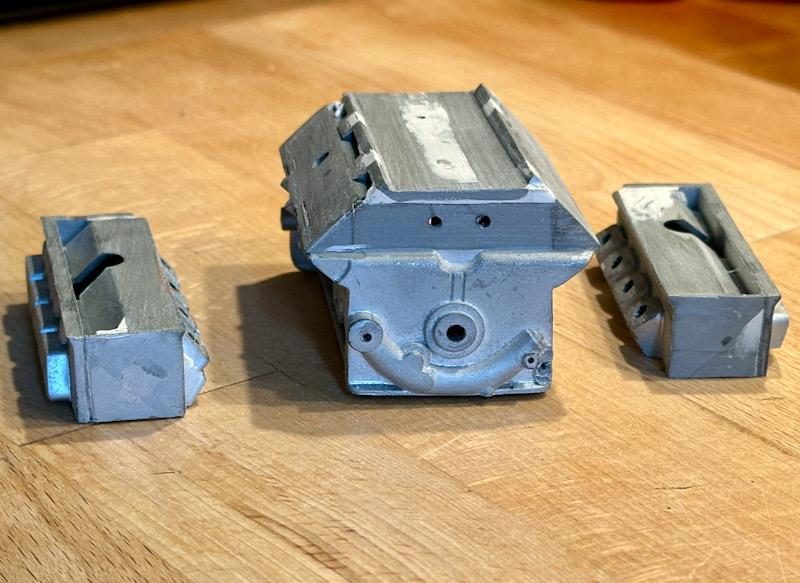
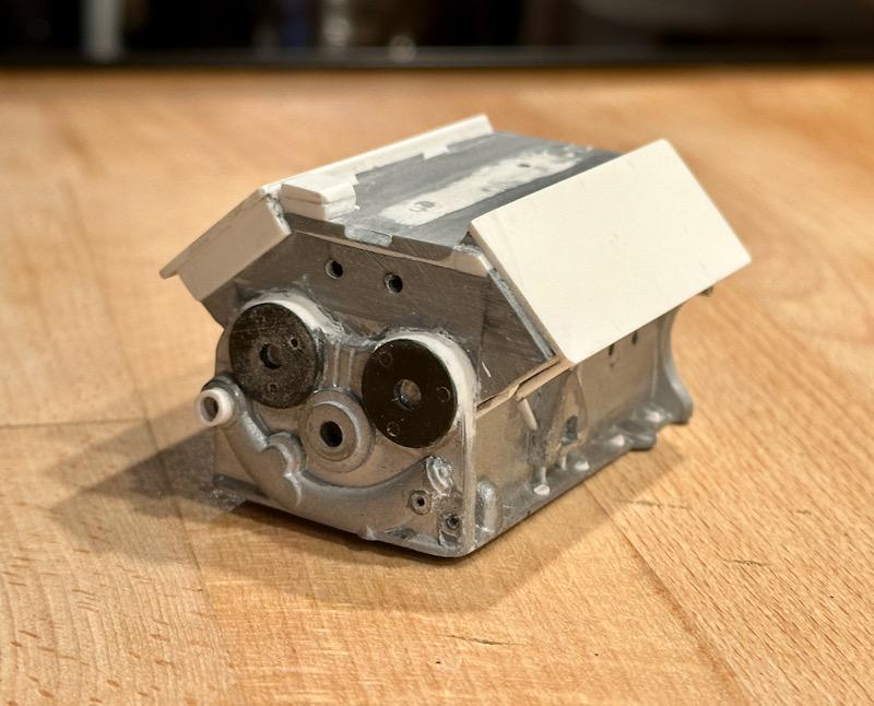
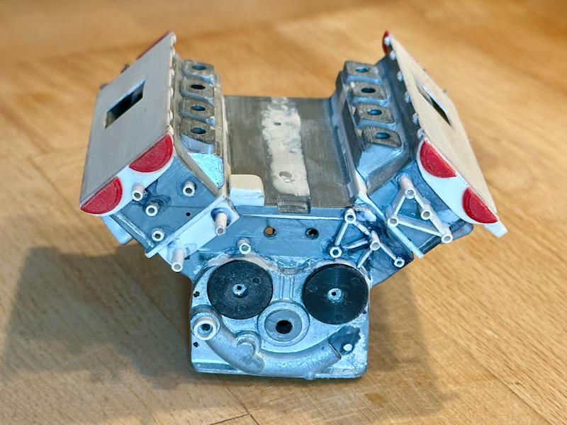
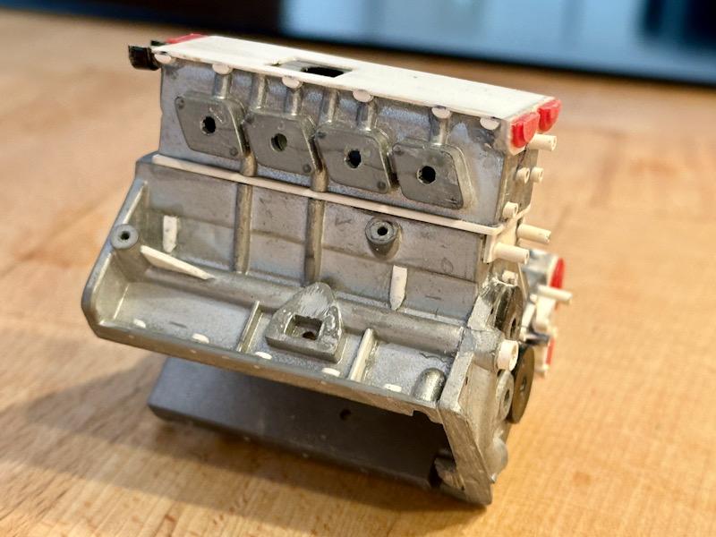
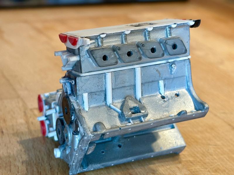
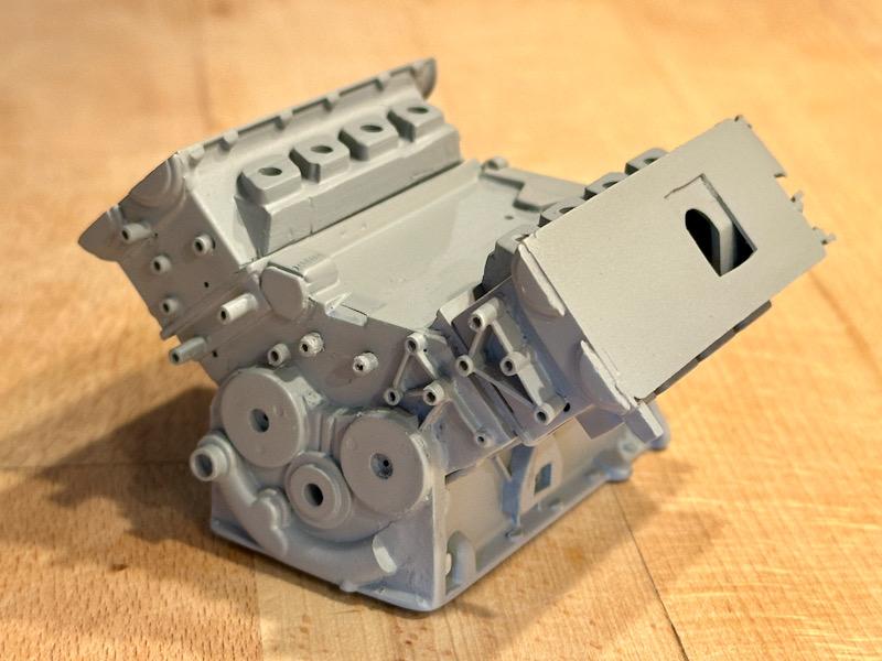
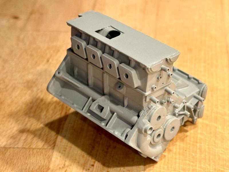
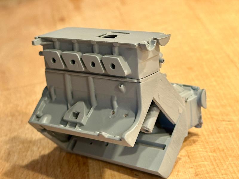
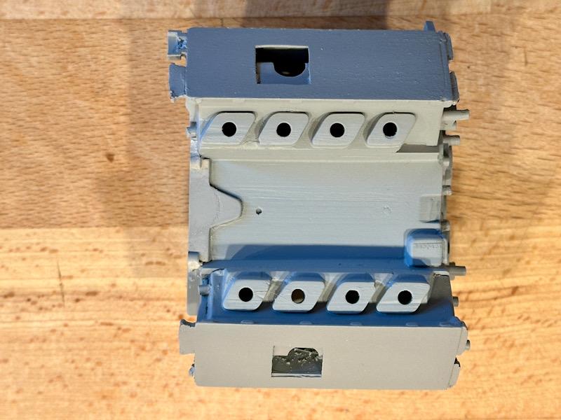
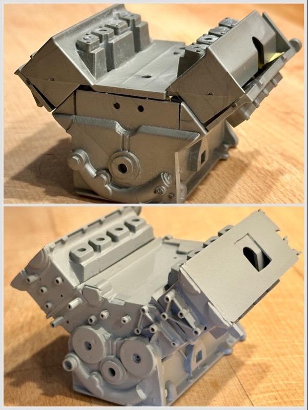
Today the work on the engine begins. As with the Testarossa, I will make 2 engines. A standalone model based on the Transkit by Tommaso Iuele. And the engine that will be installed in the car. This engine is based on the Pocher model and will be supplemented with parts from the Autograph Transkit and parts from Leadfoot Models. To ensure this engine is as close to the original as possible, I will make many additional changes and add details. I started with the engine block that will be installed in the car. The engine block consists of several parts, including the cylinder heads. The parts were glued together. As shown in the following pictures, the basic features of the original are depicted. However, many details are missing. First, I adjusted the area of the intake flanges on the cylinder heads. Molded screws were removed, and cavities were filled. Additionally, all gaps in the adhesive areas were filled with putty. The top surface of the engine block was also filled. Then, I cut off the cylinder heads with a fine saw. Next, the engine block was supplemented with ABS parts. The surface to the cylinder heads was doubled with a 1mm plate. The shape in the area of the belt drive was adjusted. Furthermore, missing oil and water channels and screw connections to the oil pan were added to the sides. Then the cylinder heads were mounted, and the missing screw connections and ribs in the area of the belt drive were added. Additionally, the surface to the valve covers was doubled, screw connections to the valve covers and the lower half of the bearing shells for the camshafts were added. The bearing shells were previously separated from the valve covers. Then everything was primed. In a direct before-and-after comparison, you can see what can be done with a little patience to improve the engine block. That's it for today. Next, the transmission for this engine will be made. See you soon Your Ferrarifan
-
Thanks for the compliment! I try to make it as real as possible😀
-
Thanks for following!
-
In the meantime they don’t have parts for the F40. But I am lucky that I bought their improved F40 tires as long as they sold it.
-
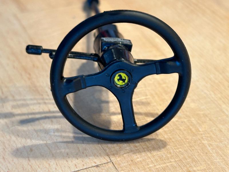
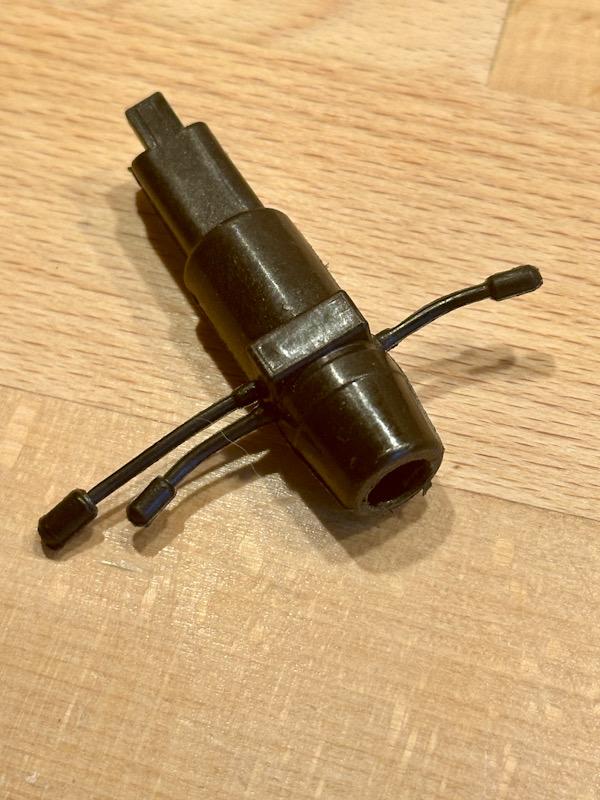
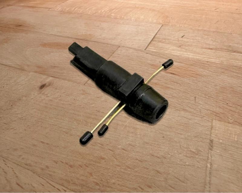
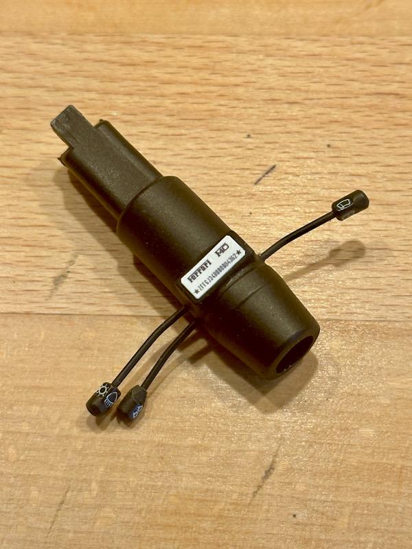
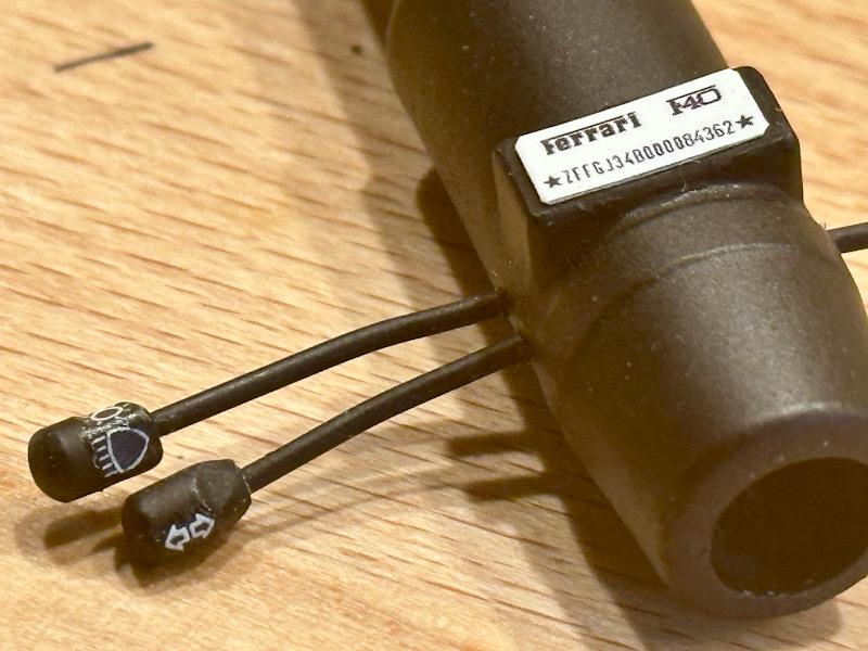
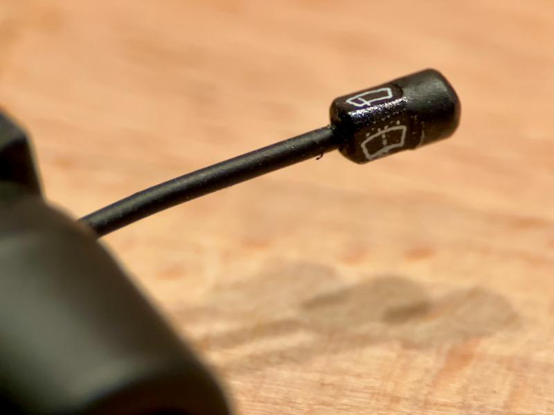
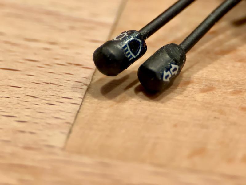
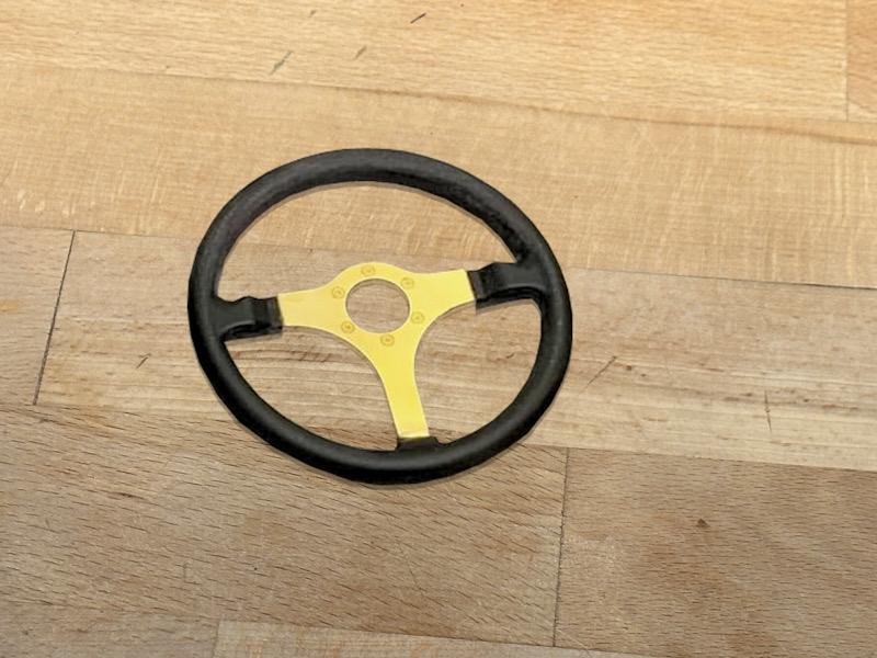
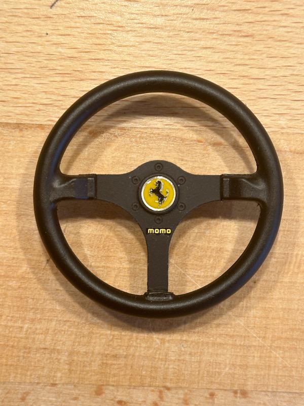
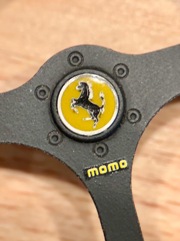
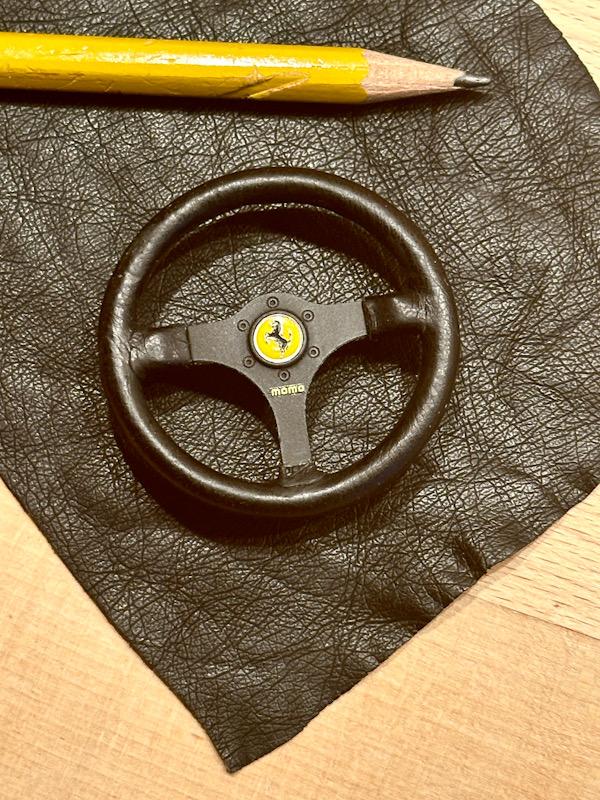
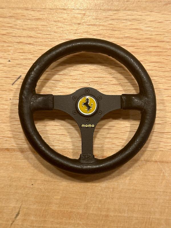
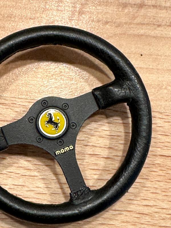
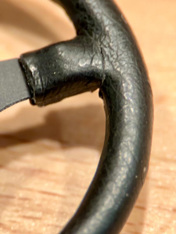
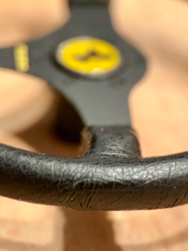
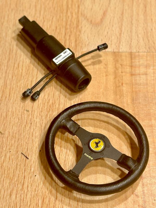
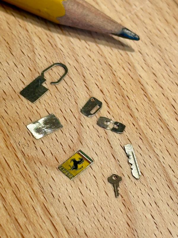
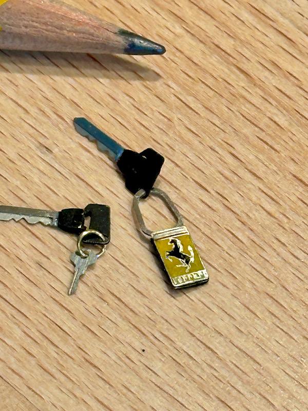
Next step is the steering column and the steering wheel. The levers for the lights and indicators on the steering column are too thick. I replaced them with thinner brass wire. After that, everything was painted. The decals on the levers are from the Autograph transkit. I made the decal for the VIN number myself. By the way, the number is from a real F40. To improve the steering wheel, there are etched and white metal parts in the Autograph transkit. After assembling the parts with super glue, everything was painted black. The emblem on the horn is an etched part. Instead of placing a decal on it, I filled the gaps with yellow and black. Once the colors were dry, I sanded everything flat to restore the metal framing. Then, everything was coated with clear varnish. To increase the level of realism, the steering wheel was then covered with synthetic leather. An old leather jacket of my wife's was used as a donor for the synthetic leather. As already described with the Testarossa, synthetic leather consists of several layers. The outer layer is made of plastic and is very thin and flexible. When synthetic leather gets older, the adhesive layer loses its grip and the outer layer can be peeled off. To cover the steering wheel, I cut out a circular ring and started gluing it on the visible side. For glue, I again used Britt craft glue. Once the inner side of the steering wheel cover was glued, the outer side was done. The seam on the real steering wheel is in the middle of the inner side. In the area of the spokes, small leather segments were then glued on. To get a clean transition in the seam area, I used a small pair of scissors designed for removing cuticles. The cut edges were touched up with matte black paint. Next, it was time for the keys. Autograph made beautiful etched parts for this. For the Ferrari logo on the keychain, I proceeded similarly to the emblem on the horn. That's it again. See you soon, Your Ferrari fan
-
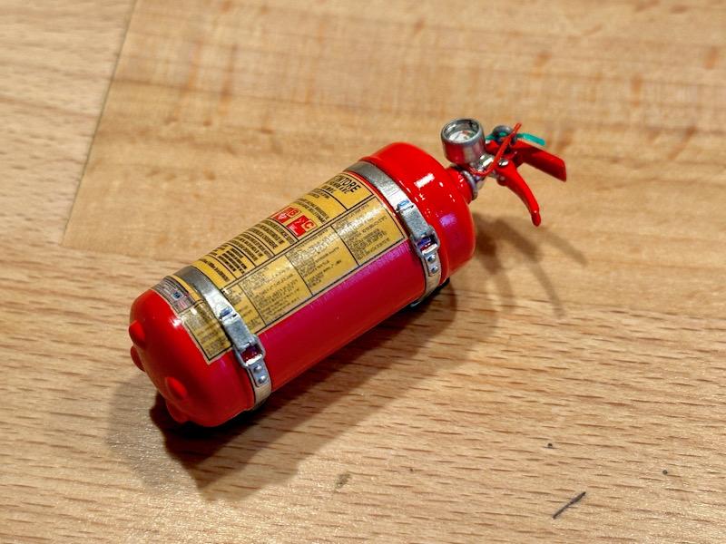
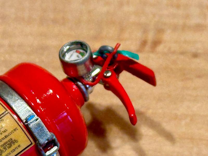
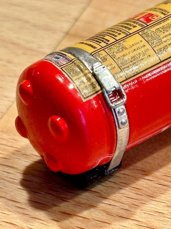
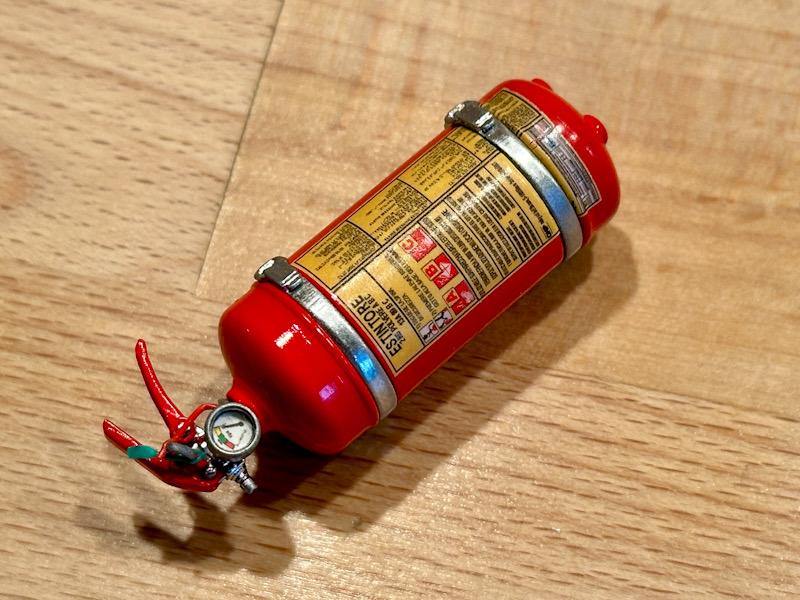
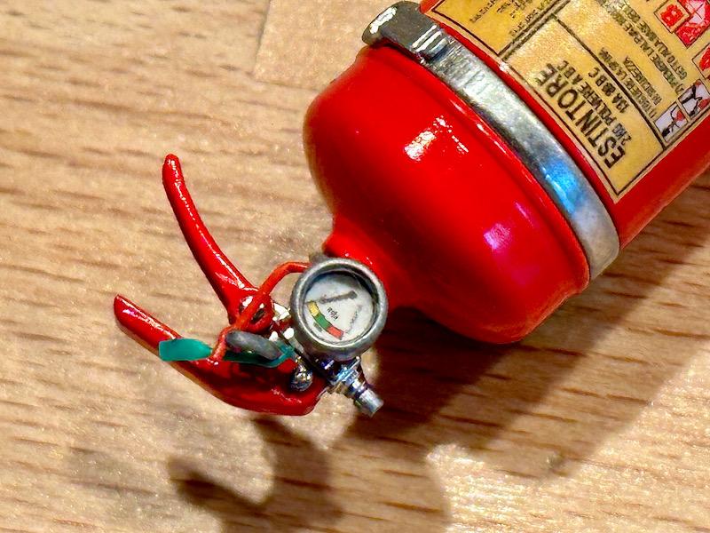
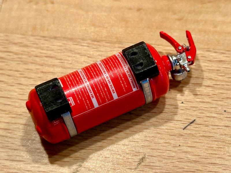
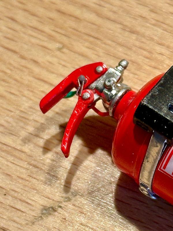
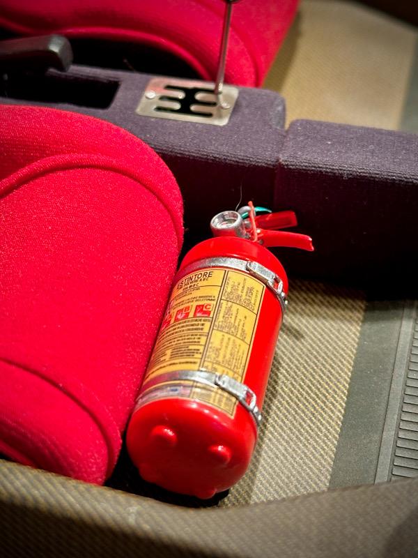
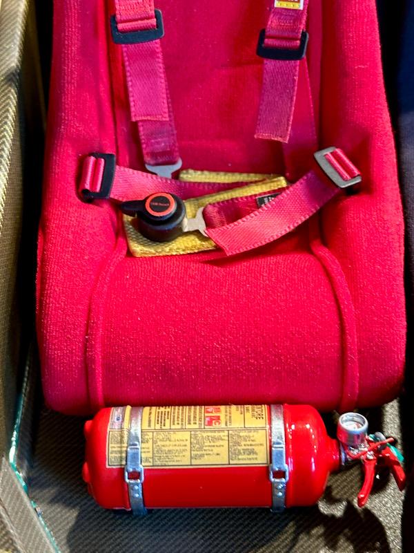
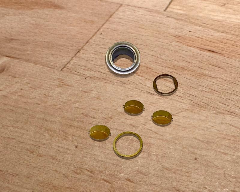
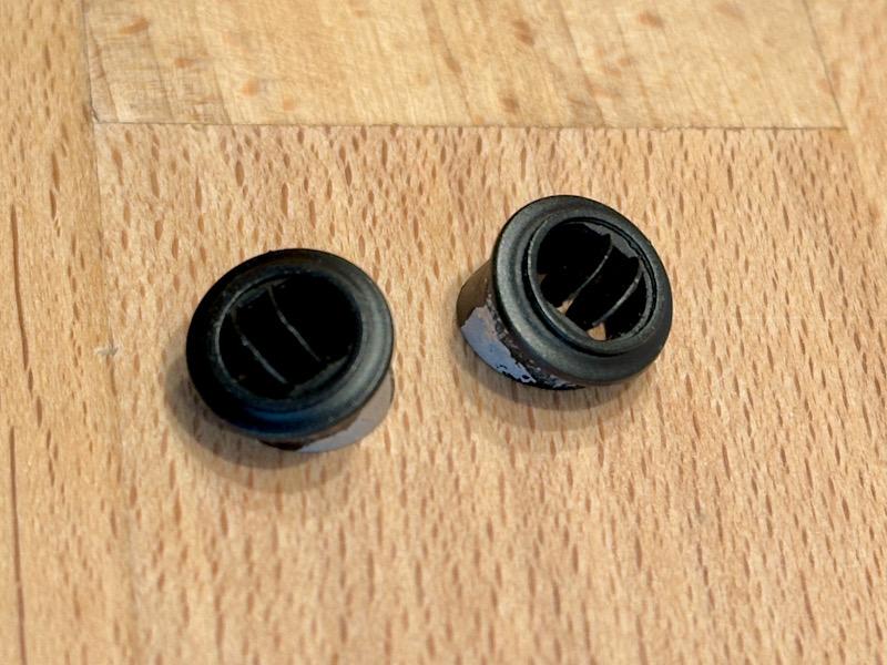
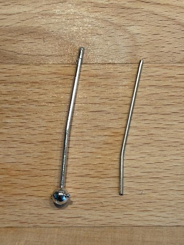
Today we're continuing with a small but, as many F40 owners have found, not insignificant accessory: A fire extinguisher Leadfoot Models (https://www.leadfootmodels.com/) offers great upgrades for numerous Pocher models, including many for the F40. One of these upgrades is a fire extinguisher that, down to the last detail, corresponds to the extinguisher that Ferrari had in their program. Unlike many other 3D printed fire extinguishers available, this one is not a single piece but consists of numerous parts. This makes it very easy to paint. It also includes very good decals. For painting, I used the following colors: Tamiya Red TS-49, Black TS-6, and Liquid Chrome by Molotow. After the colors dried, the decals were applied, and then everything was assembled. I then added small details (split pin for the safety pin, red retaining clip for the safety pin, green label, glass for the gauge). Here are pictures of the finished fire extinguisher. Here are pictures of the trial fit in the cockpit. That's it for today. See you soon! Your Ferrarifan
-
Thanks for following! Best regards Thomas
-
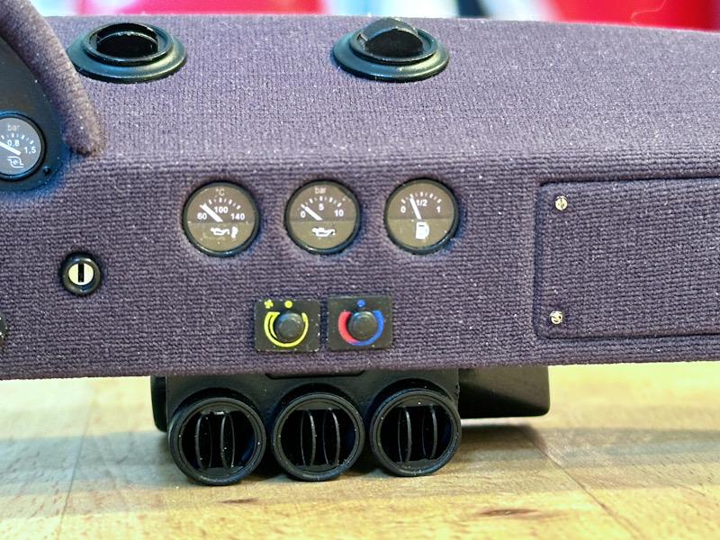
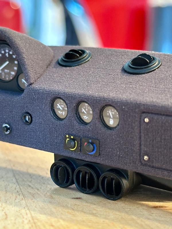
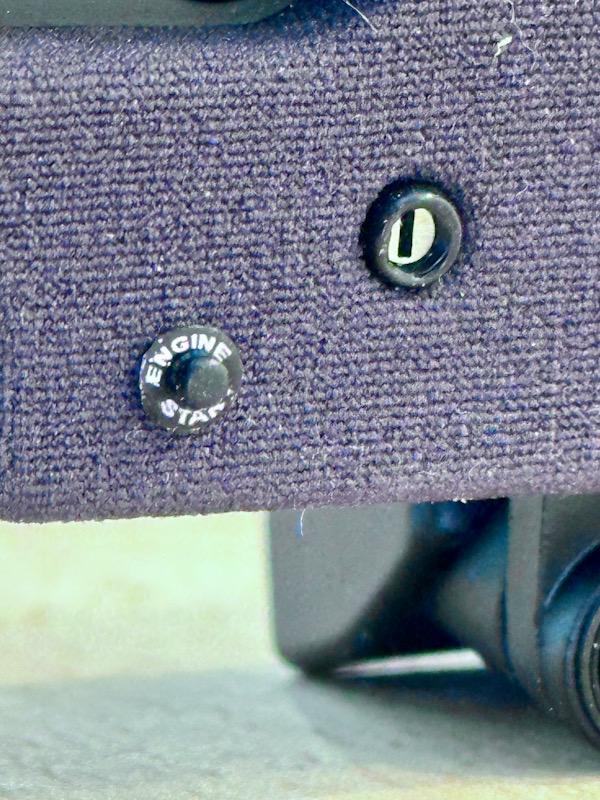
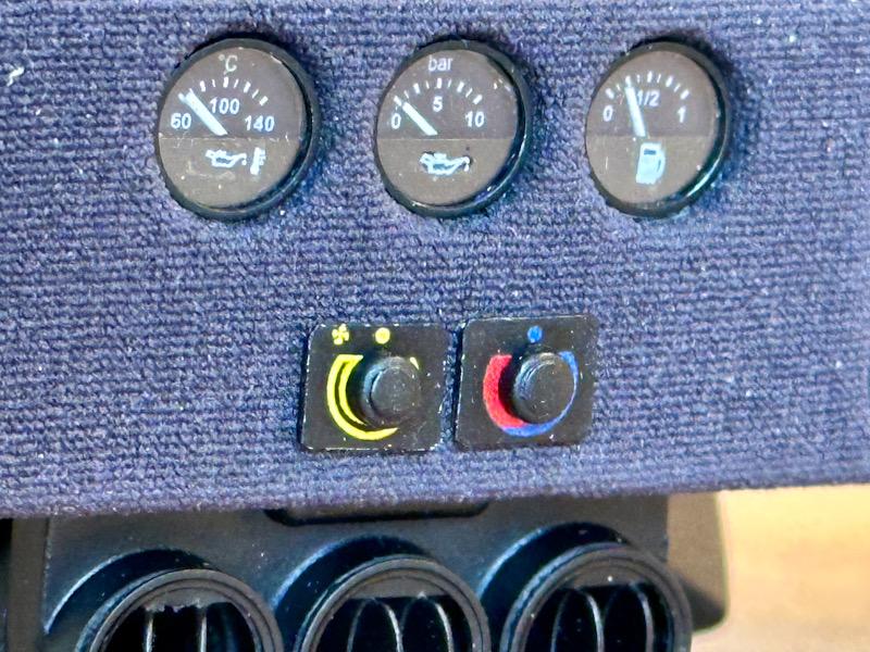
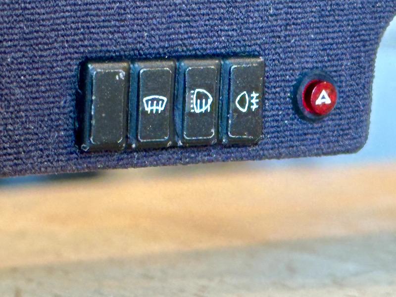
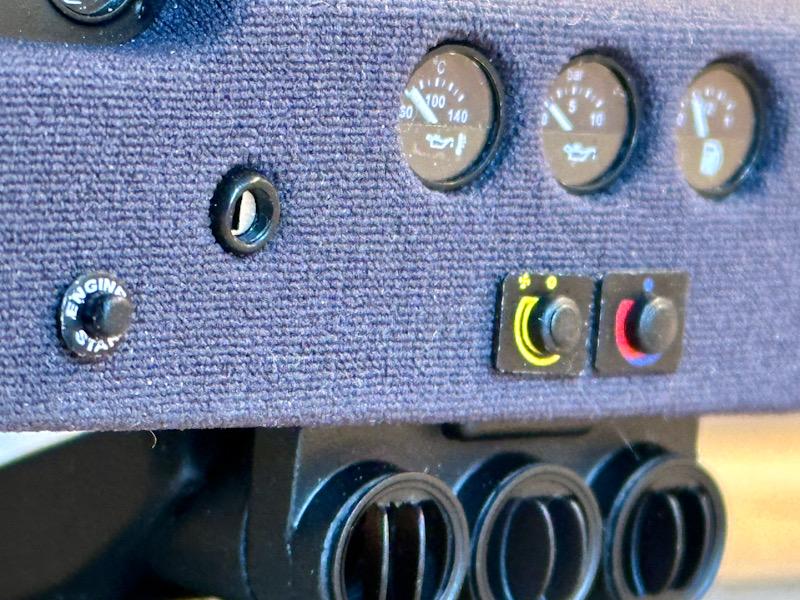
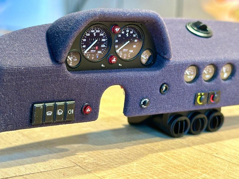
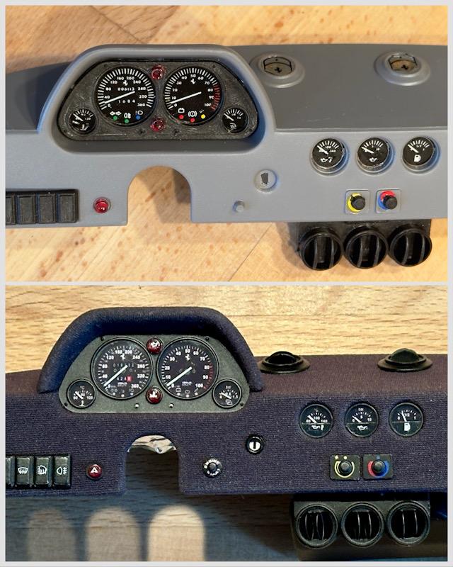
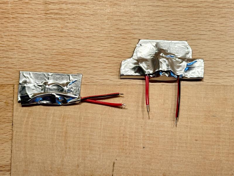
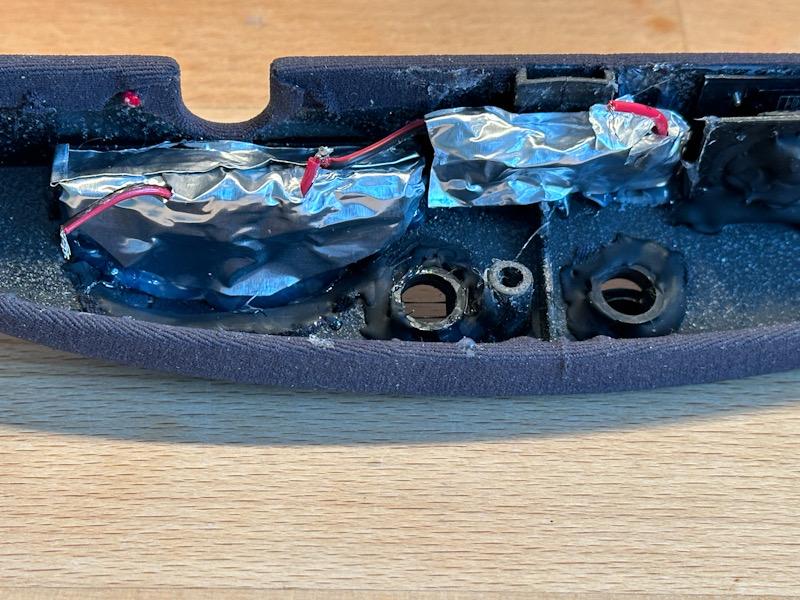
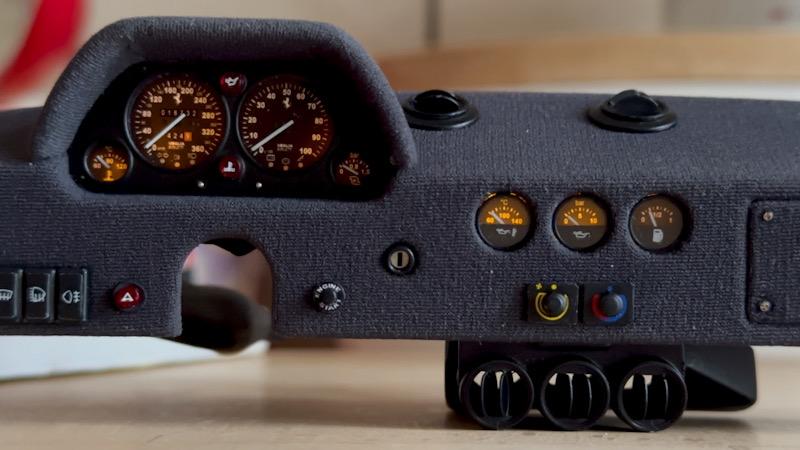
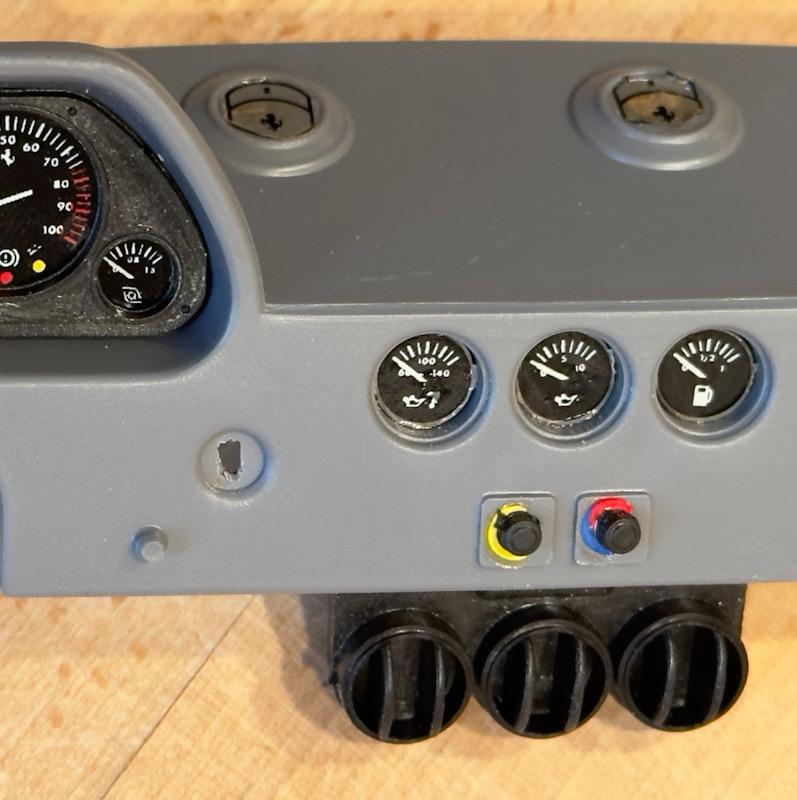
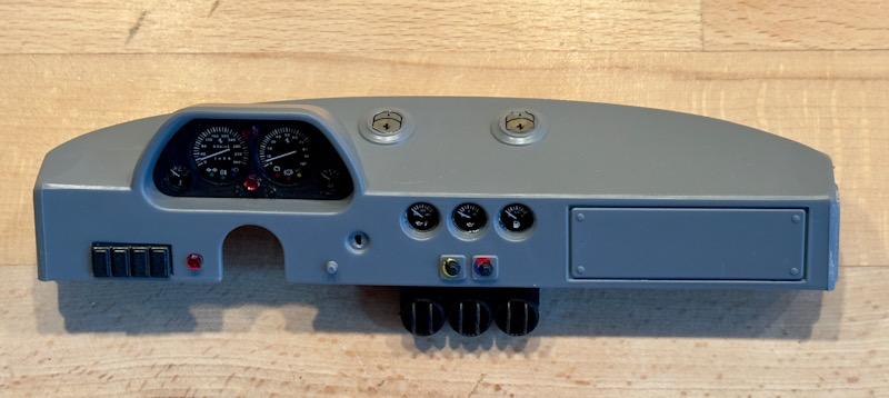
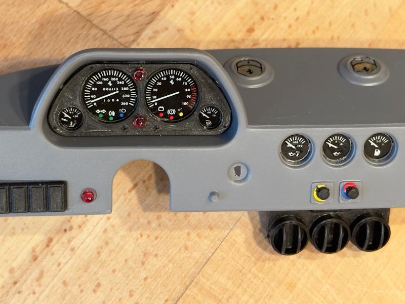
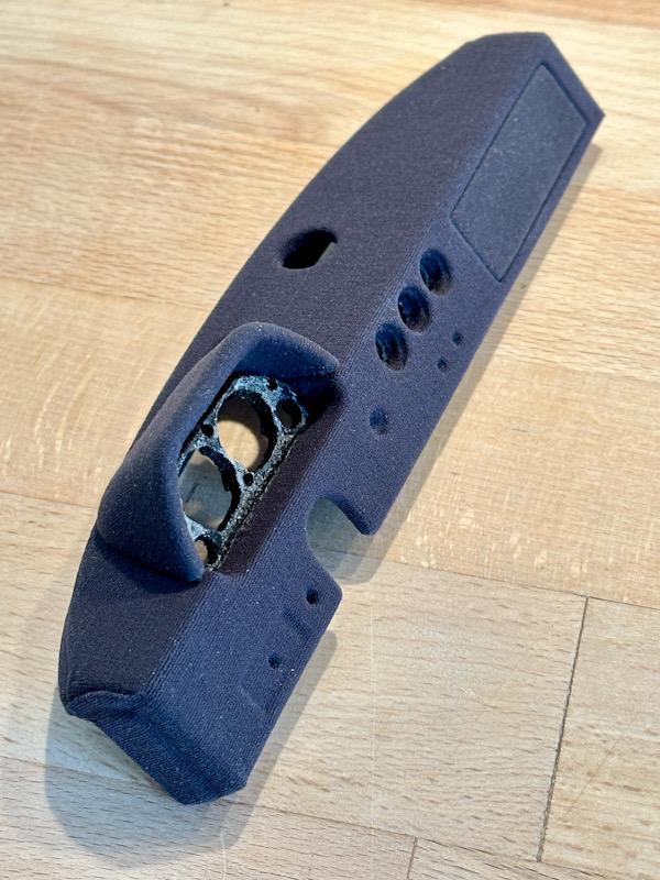
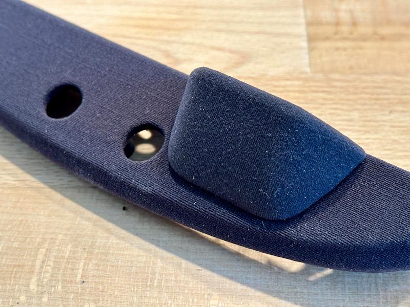
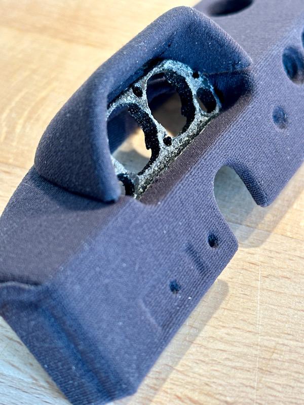
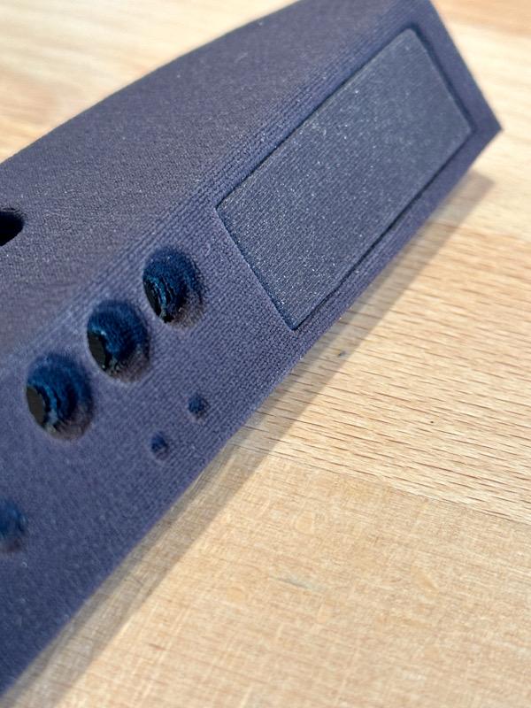
In the area of the windshield, there are two ventilation flaps on the dashboard that bring fresh air inside. An interesting detail on the side: the airflow to these two flaps is purely due to ram pressure, meaning only when the car is moving. This is another clear feature indicating that the F40 is designed as a race car. In the Pocher kit, the ventilation flaps are closed. The Autograph Transkit includes white metal parts and etched parts to depict the vents in more detail. I made the flaps in the open position. To adjust the air conditioning, there are two rotary knobs on the dashboard. One for the temperature and the other for the intensity. Since the decals from Autograph and Tommaso did not match the original, I made the decals myself in Photoshop. Additionally, I also made the decals for the start button. Next, I made the rotary knobs and the start button from ABS. Then, everything was assembled. Here are the pictures of the finished dashboard. In a direct comparison before and after, you can clearly see how the level of realism has been adjusted. The next step was the lighting. I use yellow SMED LEDs that are connected in series. As with the Testarossa, I stick the LEDs onto a transparent VIVAK plate. To increase the brightness and minimize stray light, everything is covered with self-adhesive aluminum foil. Then the lighting was mounted with hot glue. Here is the finished lighting. The aluminum foil was partially darkened with matte black. Finally, a picture with illuminated instruments. The lighting is better seen in the video. IMG_4415.mov That's it for today. See you soon, Your Ferrarifan
-
I haven’t built the 993 up to now, but it seams to be a bit more detailed but still far away from the old Pocher cars. The newer cars (Lamborghini, Lotus) are better.
-
I wanna thank everybody for the compliments and the feedback. I am looking forward to see you on my current project, the legendary Ferrari F40 in 1:8. Here is the link. Best regards Thomas
-
Ferrari Testarossa Engine - super detailed 1/8
Ferrarifan replied to Ferrarifan's topic in Model Cars
I wanna thank everybody for the compliments and the feedback. I am looking forward to see you on my current project, the legendary Ferrari F40 in 1:8. Here is the link. Best regards Thomas -
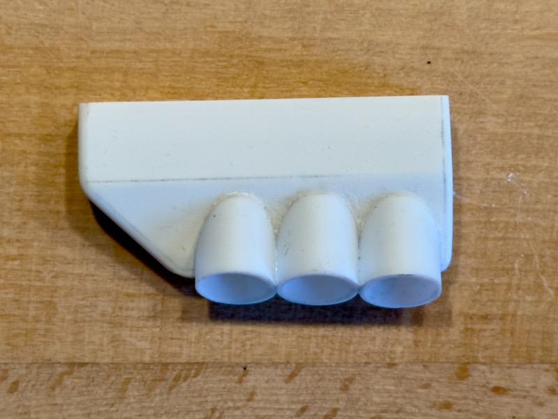
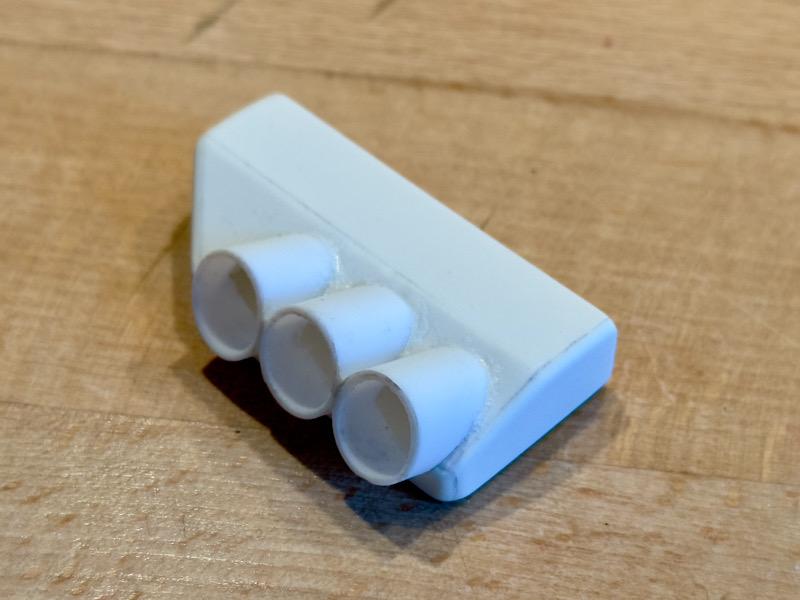
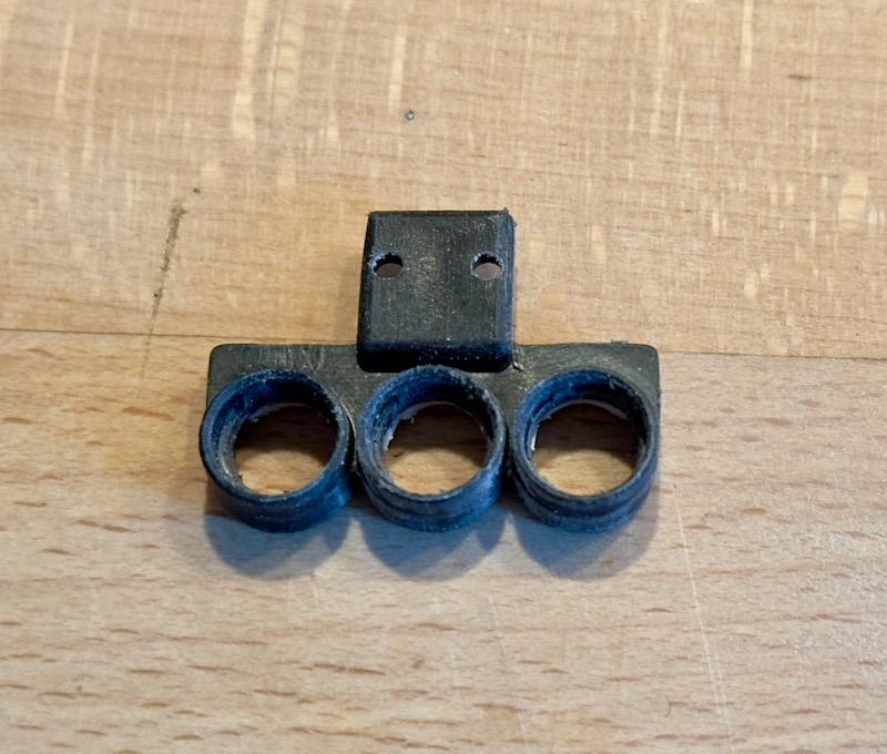
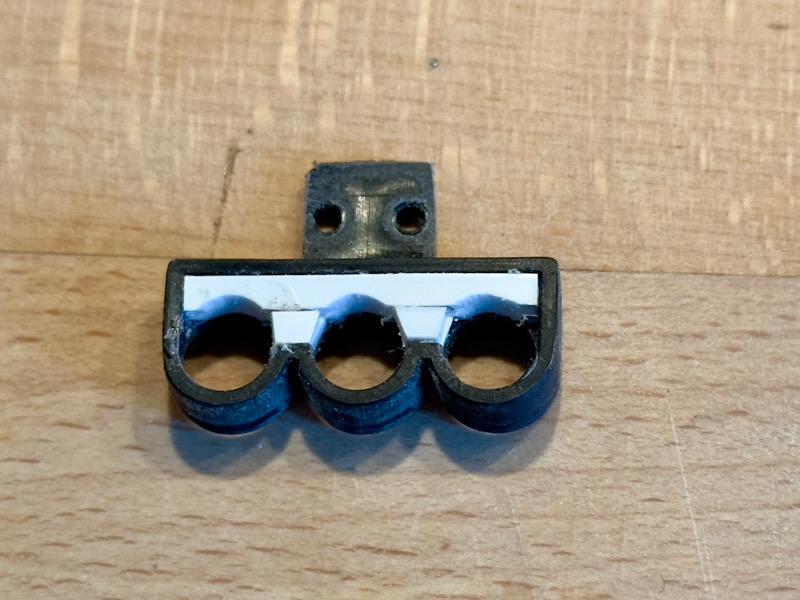
Today we continue with the air conditioning system. The air conditioning unit is located under the dashboard and has three outlet vents positioned side by side in the middle. Pocher only considered the three vents in the model, and the vents are not of exceptional quality. However, the housing behind it is completely missing. Since it can be seen in the footwell, traditional model building was called for once again. I made the housing from 1mm ABS and pipes. Then the vents were drilled out and the air guide vanes were removed. To glue the vents to the housing, the cutouts on the back were filled with ABS. The transkit from Tommaso Iuelle includes etched parts for the vents. The etched parts were fixed with super glue. This is how the vents look with the installed etched parts. Next, the housing and vents were glued together and then painted matte black. Here are the pictures of the finished air conditioning system. The air conditioning unit is then simply clipped into the dashboard. That's it for today. Next time, the dashboard will be completed. Yours, Ferrarifan
-
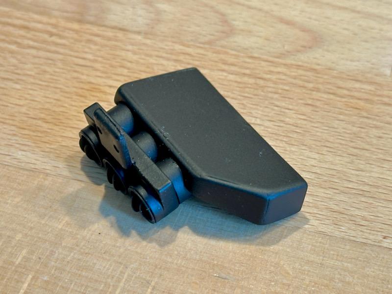
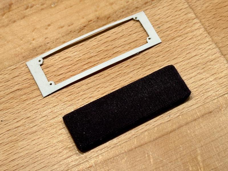
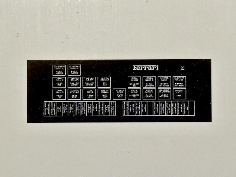
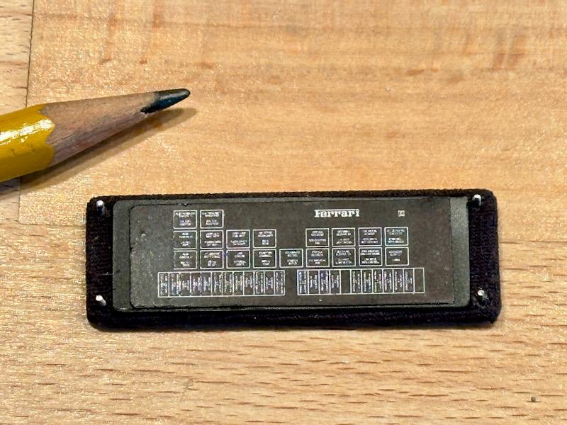
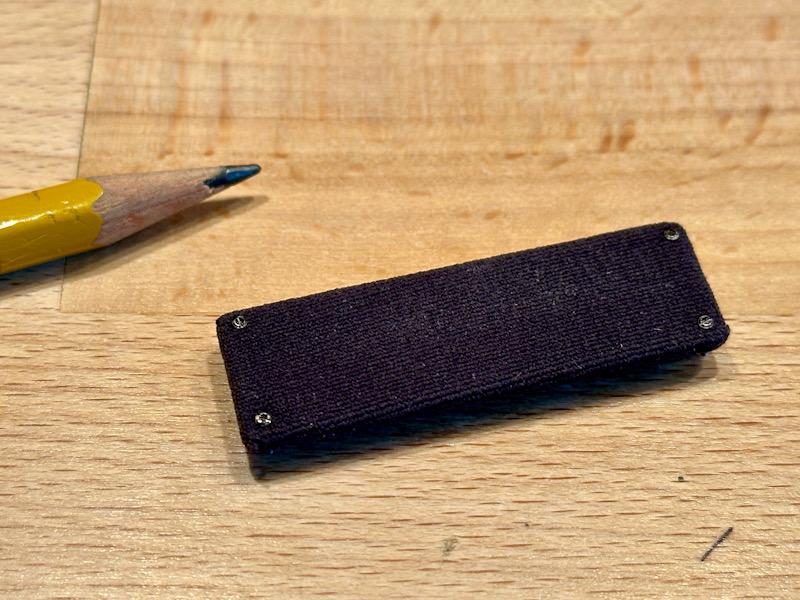
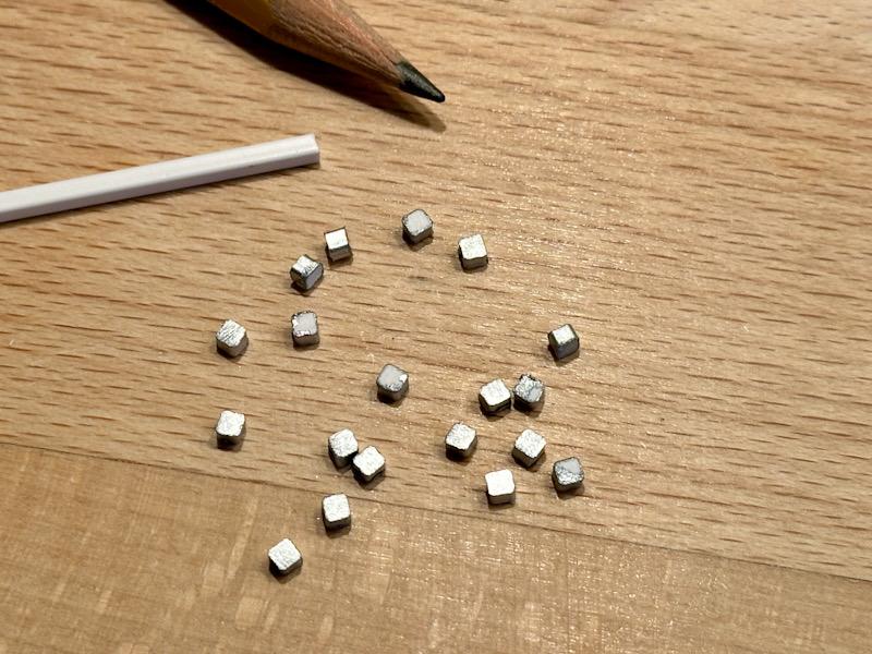
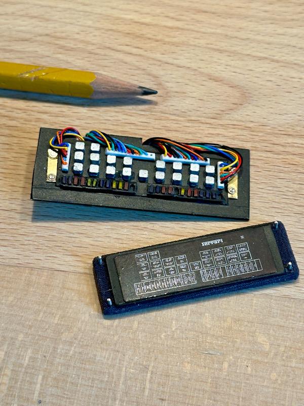
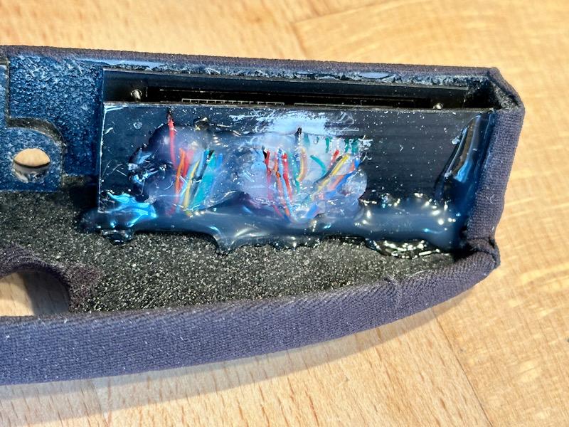
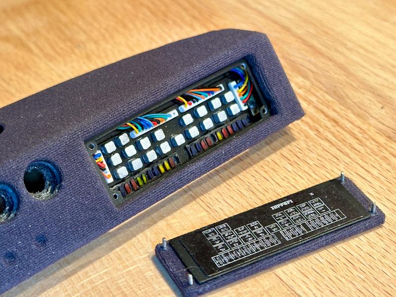
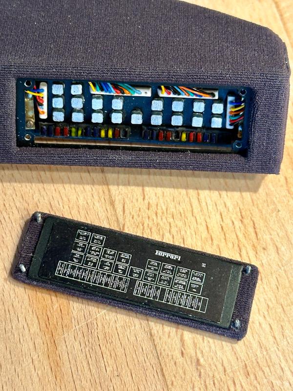
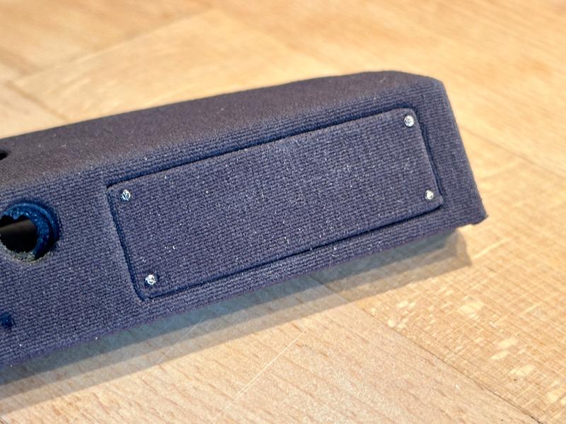
Now, let's continue with the main board for the relays and fuses. It is hidden behind the cover on the dashboard. First, I made the sheet metal from thin ABS to which the cover is screwed. After painting, it was glued to the inside of the opening in the dashboard. On the inside of the cover, there is a sticker with a schematic representation of the board and the designation of the individual relays and fuses. I created it in Photoshop based on original images and labeled it correctly in two languages. Unfortunately, the resolution of my inkjet printer is not sufficient, and it is no longer readable. Afterward, the label was attached to the cover. I also added screws so the cover can be easily mounted and dismounted. Then I started building the main board. As a base, I used 1mm ABS. I made the connectors for the fuses from parts of JST ZH 1.5 mm connectors, which I use for the lighting wiring. The relays were made from pieces I cut from a 3mm rectangular profile. The fuses were made similarly from a transparent Vivak strip. This is how the finished main board and cover look. The cables have a diameter of 0.4 to 0.6 mm. The board was then attached to the dashboard with hot glue. Finally, here are some pictures of the finished area. Although more could have been done with 3D printing, I am more than satisfied with the overall impression. That's it again! See you soon, Your Ferrarifan
-
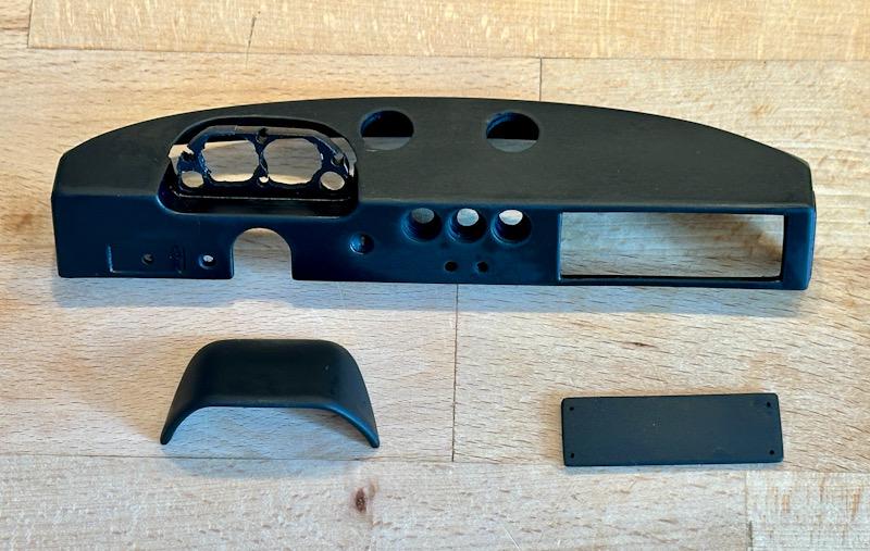
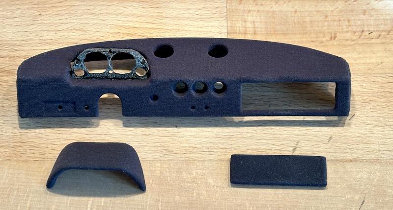
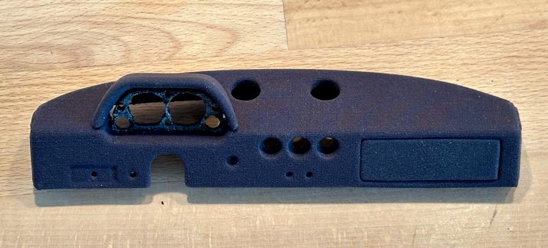
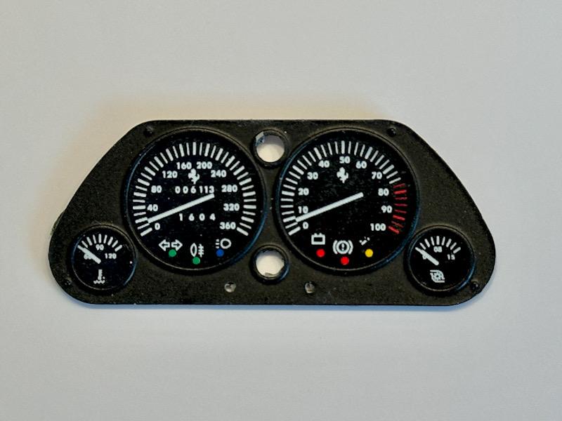
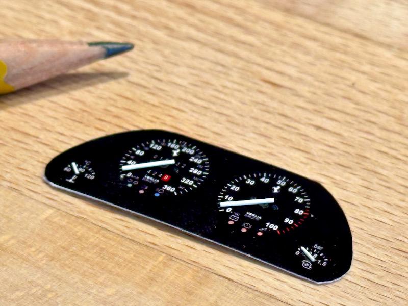
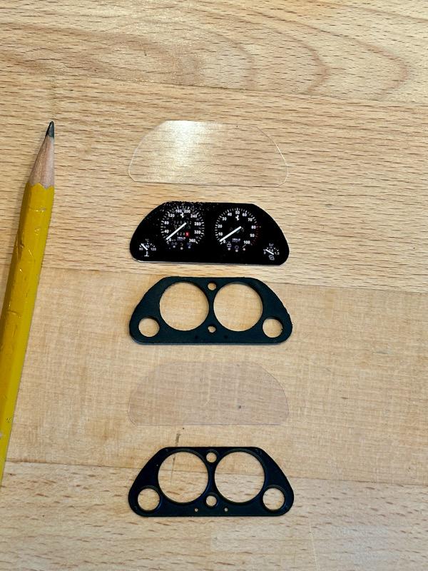
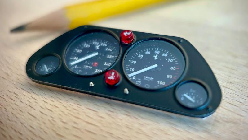
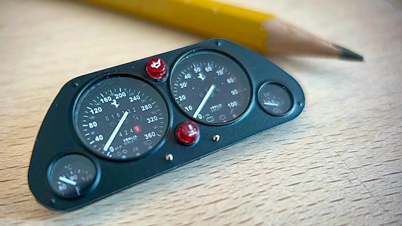
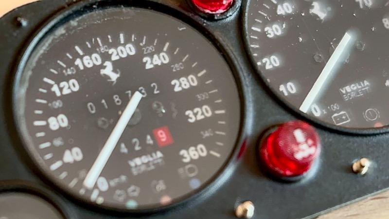
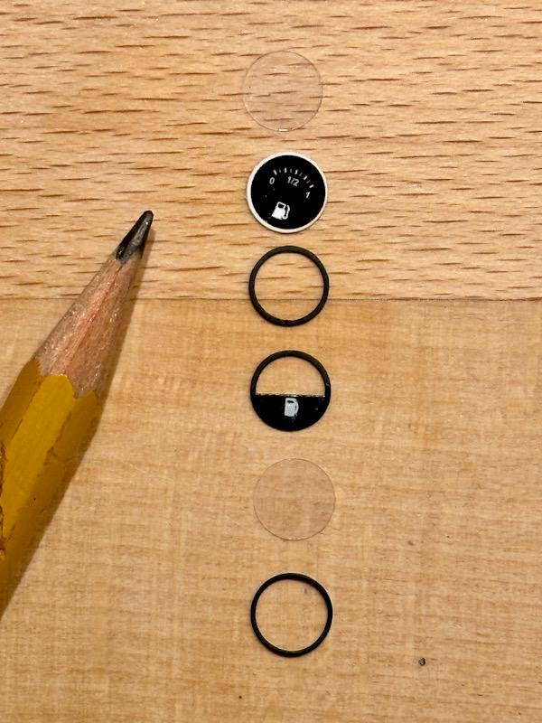
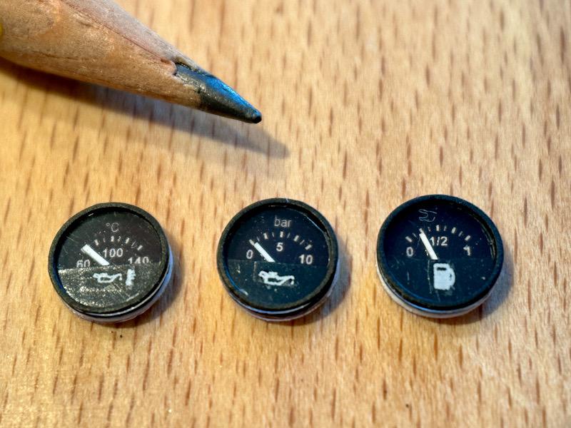
Here we go with the dashboard. Here are two pictures of the starting point. After removing all the attachments, the dashboard was divided into three parts, just like the original. This makes it easier to cover the parts with the pantyhose fabric. Holes were also drilled into the instruments for the planned backlighting. Then the upper ventilation openings were drilled out because there are etched and white metal parts as replacements in the Autograph transkit. After that, the parts were covered with the fabric. Next were the instruments. The Autograph transkit includes improved decals for this. However, since the decals only partially match the original, I created matching graphics in Photoshop. The graphic was then printed on white decal paper. To increase the realism, pointers and screws were added. The transkit includes beautiful etched parts to build up the instrument panel in layers. The individual layers were then carefully assembled with a few drops of super glue. The layered construction makes the instrument panel look very realistic. I proceeded the same way with the middle instruments. First, create the graphics in Photoshop, then build them up in layers. Thus, the instruments are finished. The backlighting will be done later. That’s it for today. See you soon, Your Ferrarifan
-
Thanks for the hint. I know them and will also use parts from them. They made excellent rubber tires for the F40. And I was lucky to get one pack before they were sold😁. Best regards Thomas
-
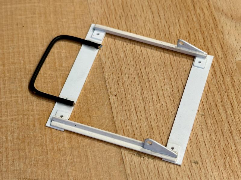
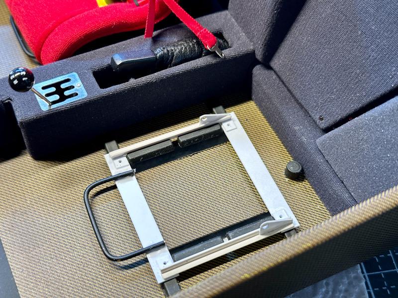
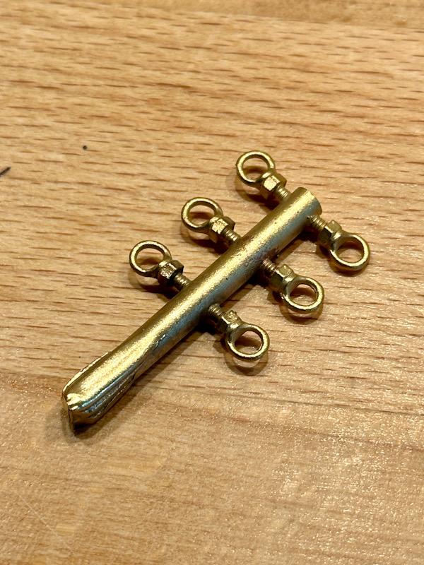
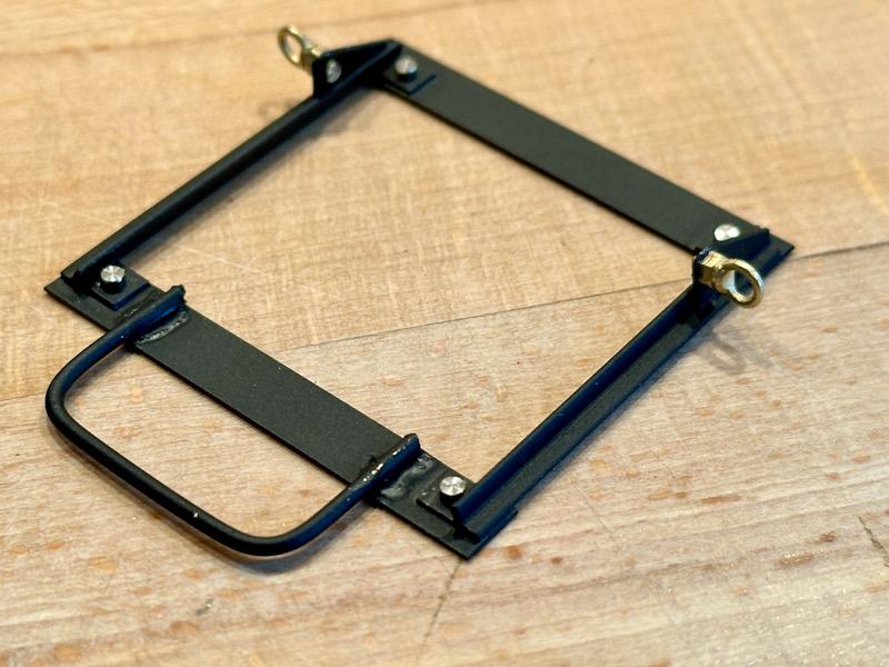
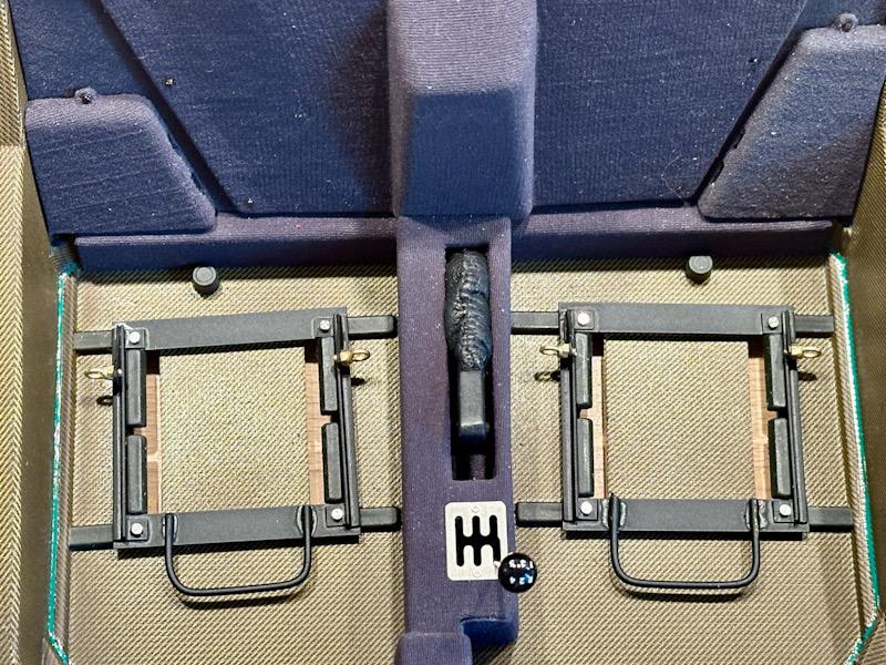
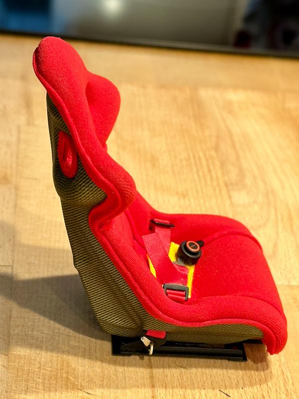
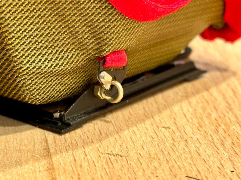
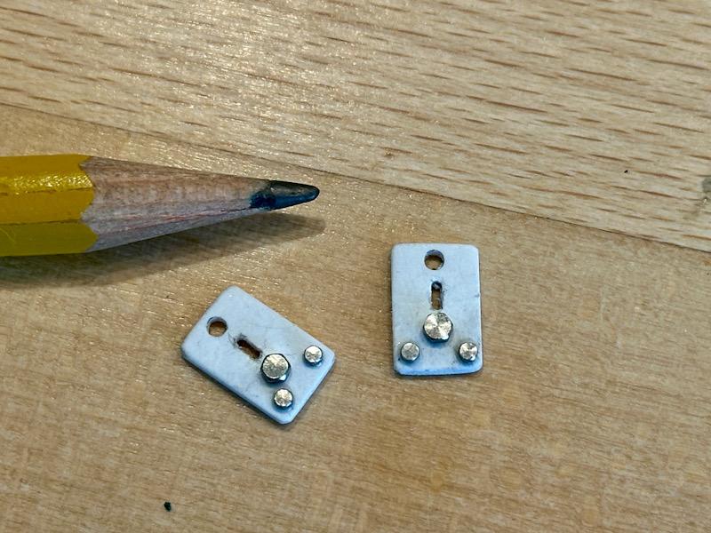
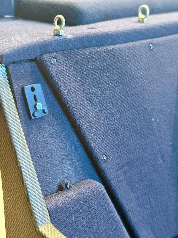
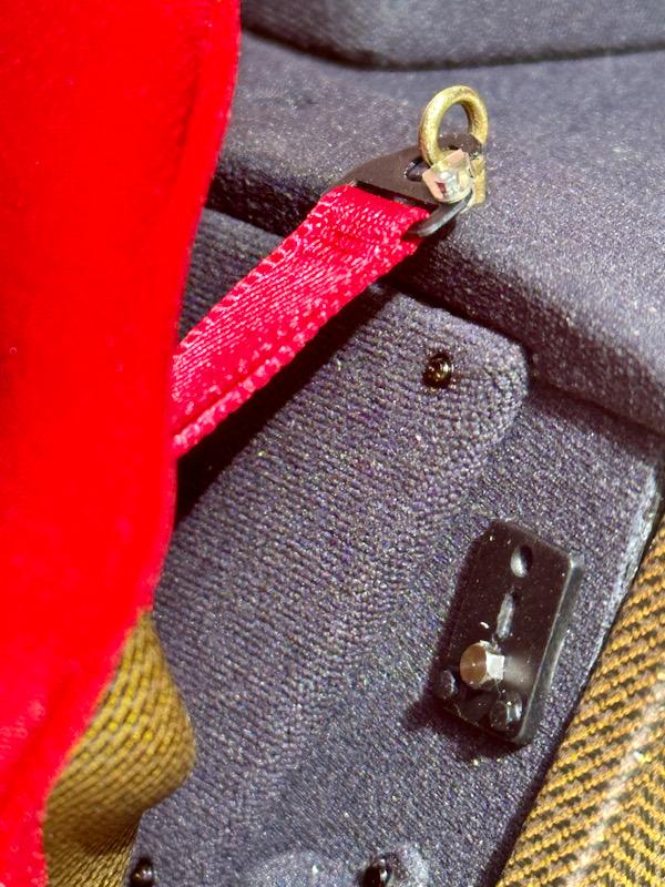
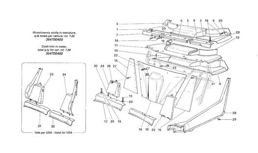
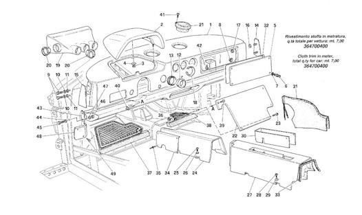
Let's continue with the seat rails and the belt attachment. The F40 has a simple seat rail. This is completely missing in the Pocher model. In the Autograph Transkit, there is only a photo-etched part for the 3-point belt. However, since the 4-point belts are attached to the seat rail on both sides of the seat, simple model building was required again. I made the seat rail from PSA L-profiles and strips. The rail is then simply placed on the actual seat mounting. When the seats are locked in place, the seat rail is fixed. Eye bolts are used to fasten the 4-point belts. Although the Autograph Transkit includes parts for this, they do not match the original dimensions. After a long search, I found suitable eye bolts at Knupfer.info After the seat rails were painted black, the eye bolts and the screws for fastening the rails were installed. Another test fitting after painting. Here you can already see how the seats are installed at an angle. This corresponds to the original. Since the footwell becomes very narrow due to the wheel arches, this is the only way to sit comfortably. However, it takes some getting used to, especially for the driver. As previously described, the F40 was sold with either 3-point or 4-point belts. According to my research, the rear mounting plate for the 3-point belt was also factory-installed in vehicles with 4-point belts. I made the plate again from ABS and fitted it with screws from Autograph. After painting, the plates were mounted on the rear wall. Additionally, the rear eye bolts for the 4-point belts were installed. Before clipping in the seats, the belts were placed on the rail and the belts were hooked in. This would not have been possible after seat installation due to space constraints. Then the seats were mounted and the belts clipped in at the top. The holes between the belt loops are for the steel tubes of the frame that run diagonally upward along the rear wall to the roof. Since I am building the car in a slightly used condition, the seats, belts, and footwell were lightly soiled with pigments. Unfortunately, this does not come across well in the photos. That's it for today. Next time, we'll continue with the dashboard. See you soon, Your Ferrarifan
-
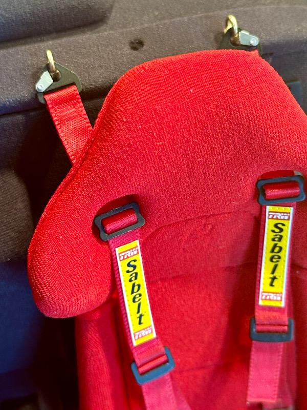
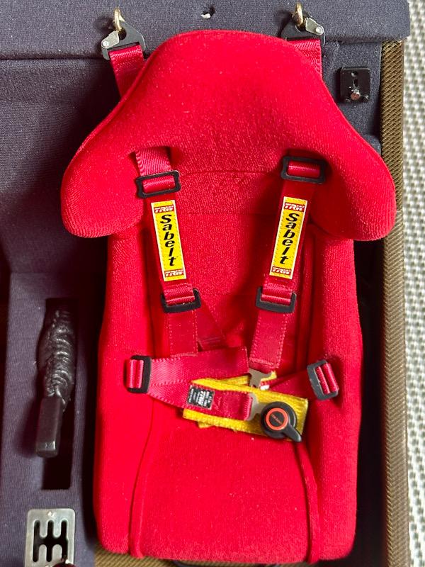
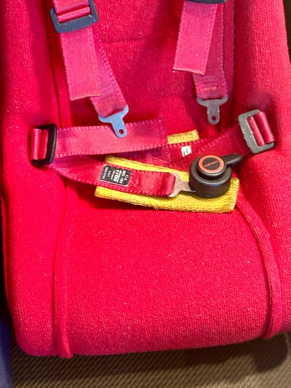
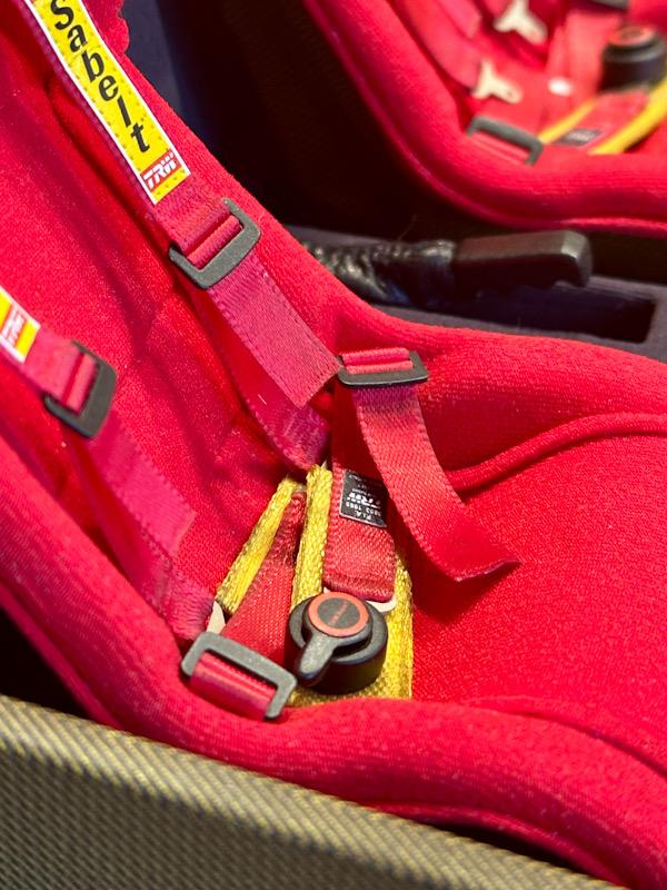
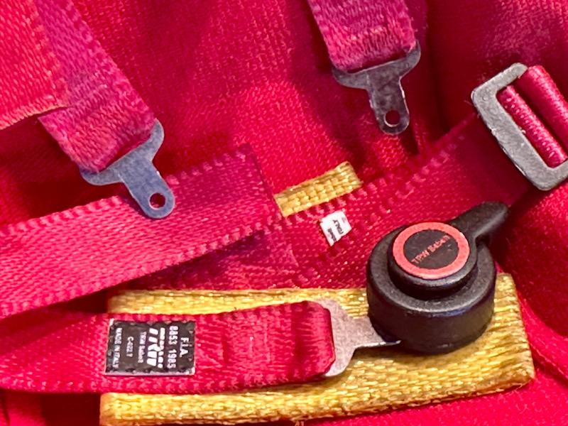
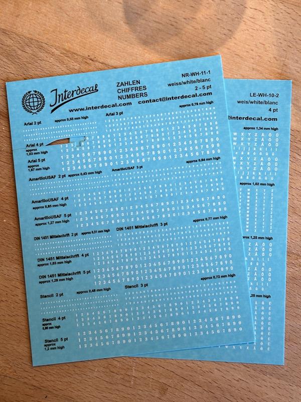
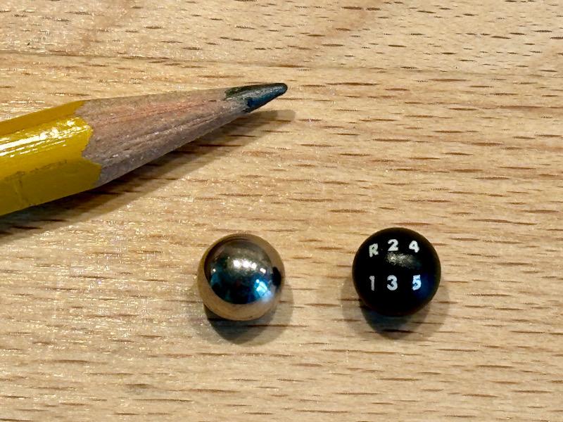
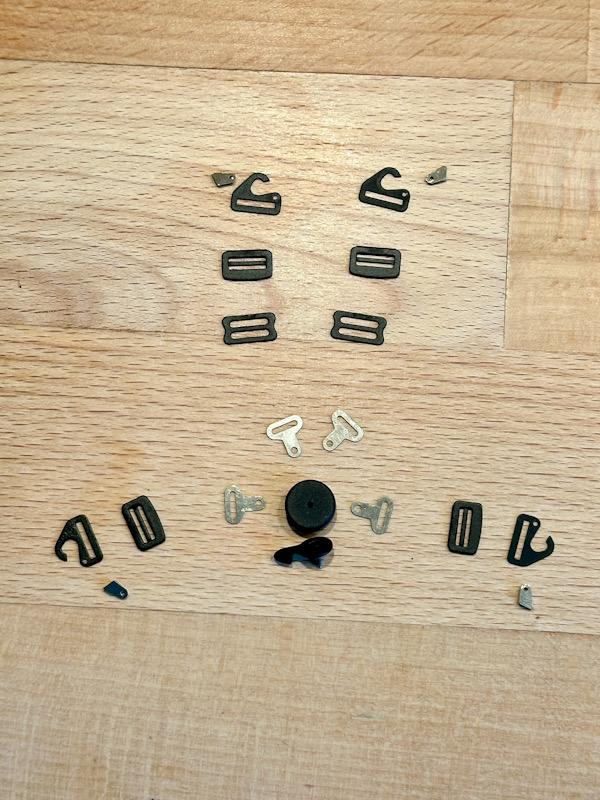
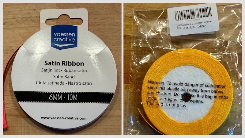
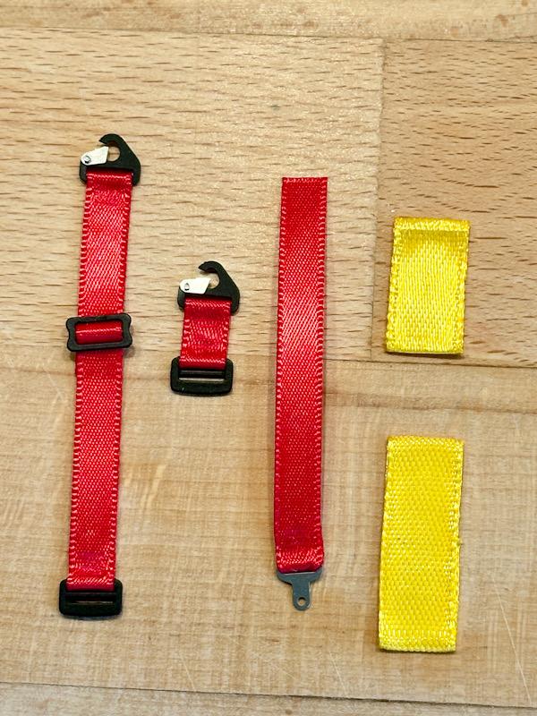
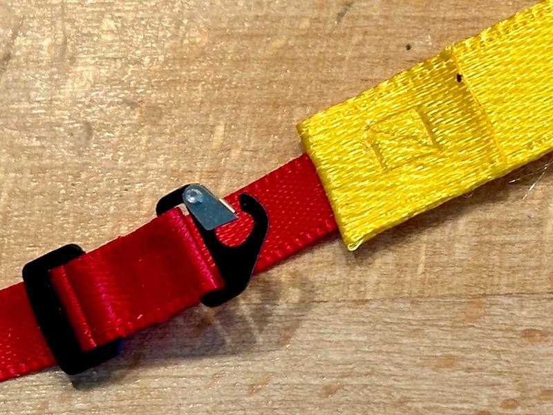
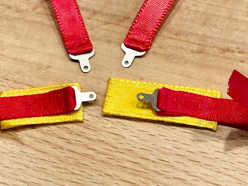
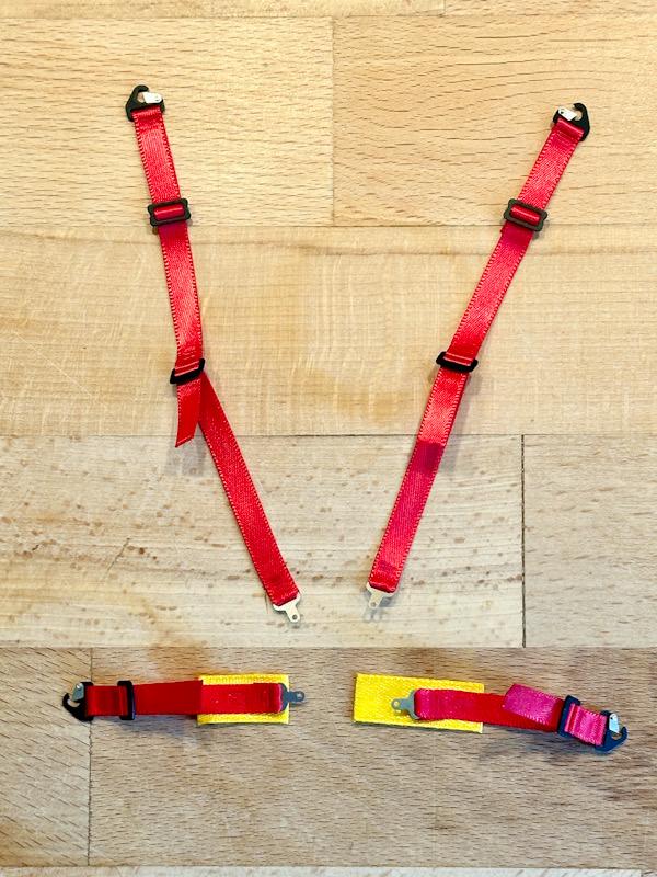
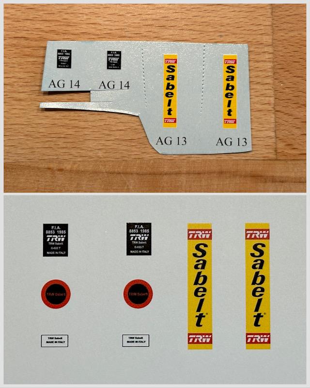
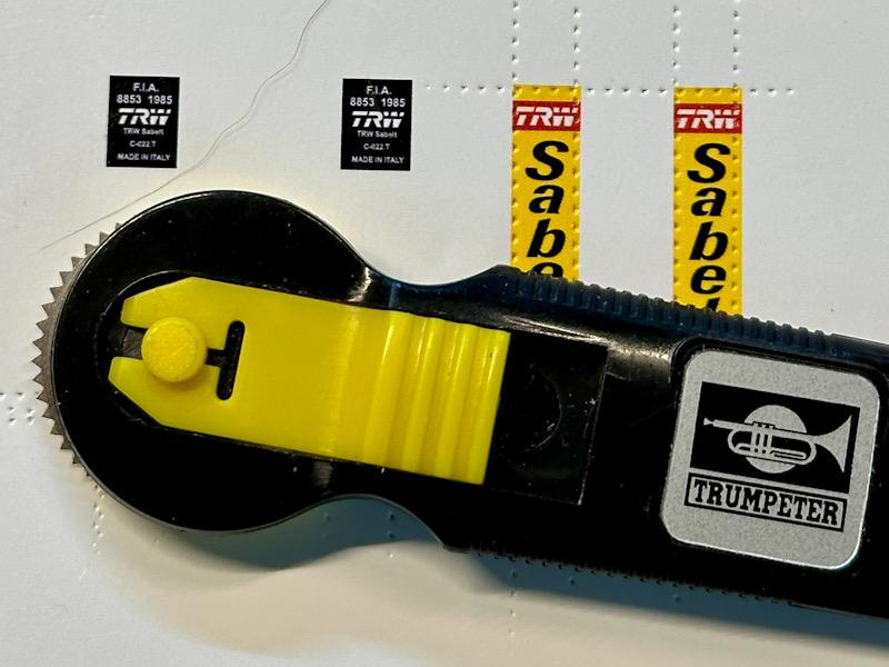
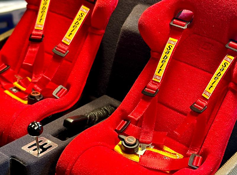
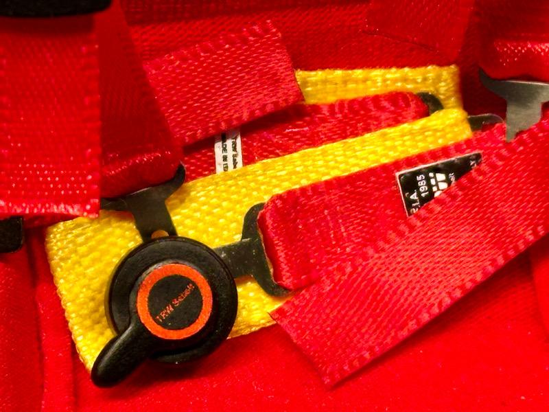
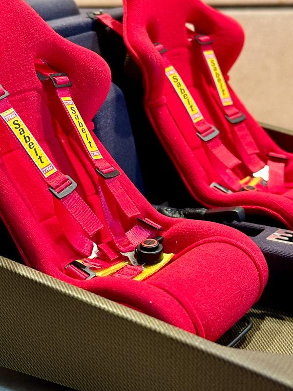
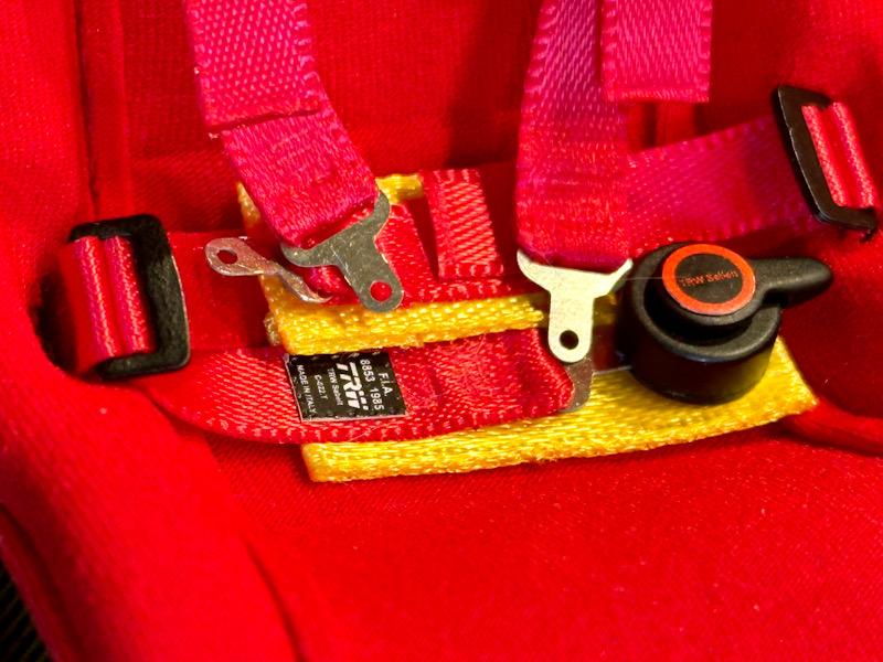
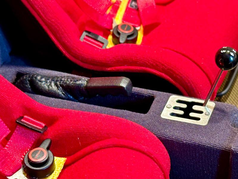
Let's continue with the center console. In the original, the handbrake is covered with a leather sleeve. I recreated the sleeve from very thin leather by sewing two halves together. For this, I placed the visible sides together, sewed them, and then turned them inside out so that the visible side was outside again. Next up was the gear stick. I replaced the plastic part with a metal rod. The rod is part of a transkit from Scaledetails. The transkit also includes a metal ball for the gear knob, which replaces the bulky plastic gear knob. In the Autograph transkit, there are decals for the gear knob labeling. However, these are not good because the print is not clean. Therefore, I used decals from Interdecal. They are of outstanding quality because they have no excess edges. I chose the font size 4pt to match the original as closely as possible. The metal ball was painted black, then I applied the labeling. Finally, everything was sealed and polished with clear lacquer. Next are the seat belts. In the F40, the customer could choose between normal 3-point belts and sportier 4-point belts. I opted for the sportier version. The Autograph transkit includes beautiful etched and white metal parts for this purpose. The parts were painted black to match the original. For the belts, the Autograph transkit includes a red satin ribbon and yellow foam pieces for the padding in the area of the central lock. However, the foam does not match the original at all, and the red satin ribbon is too coarse in texture. I found suitable replacements on the internet. The belt pieces were then cut to the appropriate lengths. To prevent the ends from fraying, they were sealed with a soldering iron. Afterwards, the etched parts were threaded through and the belt ends were glued with superglue. The fastening hooks have a movable part so that they can be hooked into the fastening loops. In the original, these are riveted. For this, I used rivets from Model Factory Hiro (Metal Rivets Series No. 05: Round socket hexagon-head rivets L No: P1012). In the original, the belt ends or the red and yellow belt segments are sewn together. I simulated the seams using a soldering iron. It is important to work with a lower temperature so that not everything melts, but just fuses together. Unfortunately, the result is not very visible in the photos. Here are all the belt segments. What is still missing are the patches with the labels. The Autograph transkit includes some decals for this. However, since the quality is not optimal, and some labels are missing, Photoshop was called for once again. I then made my own labels and printed them on white decal paper. In the original, the labels are sewn on. To simulate the seams, I used the riveting tool from Trumpeter. Afterwards, the labels were cut out and glued to the belts along with the backing paper using superglue. Then I punched out the labeling of the central lock with a punch and applied it. Here are pictures of the finished belts. What is still missing are the fastening loops and the floor rails. However, I am still waiting for a delivery. Additionally, the belts and seats will be lightly aged or soiled since I am making the car in a slightly used condition. That's it for today. See you soon, Your Ferrarifan
-
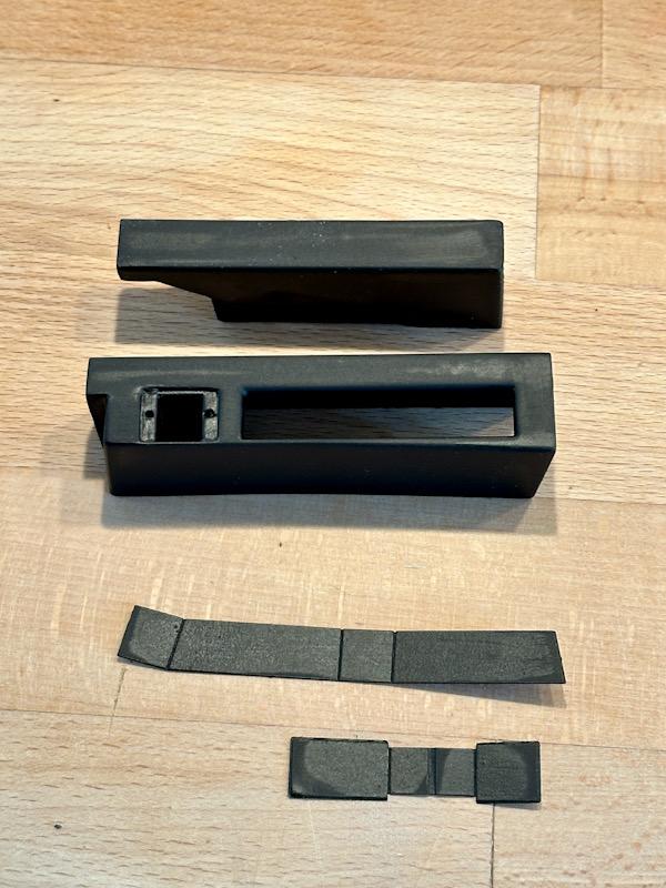
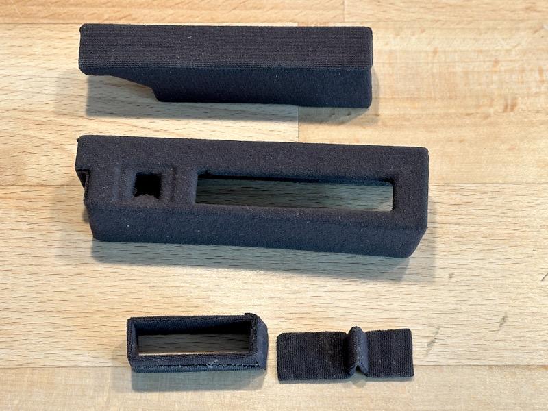
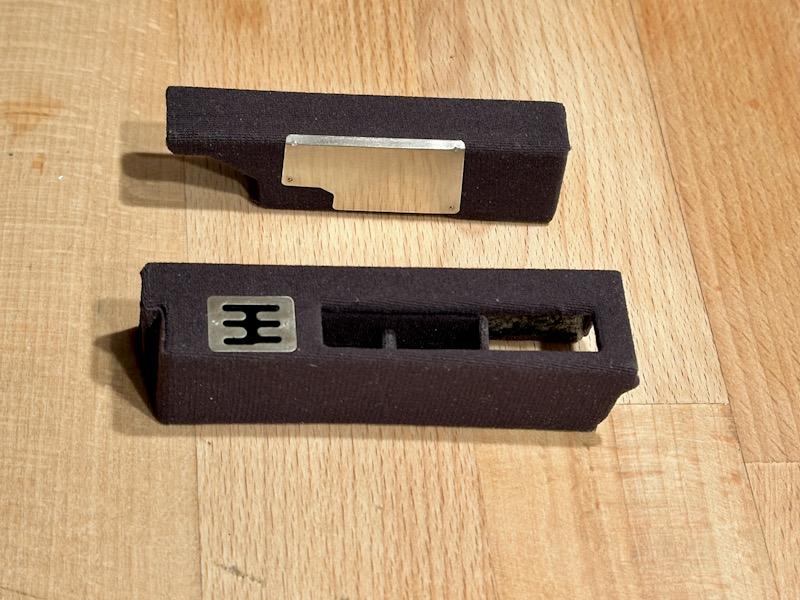
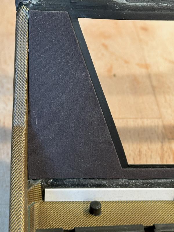
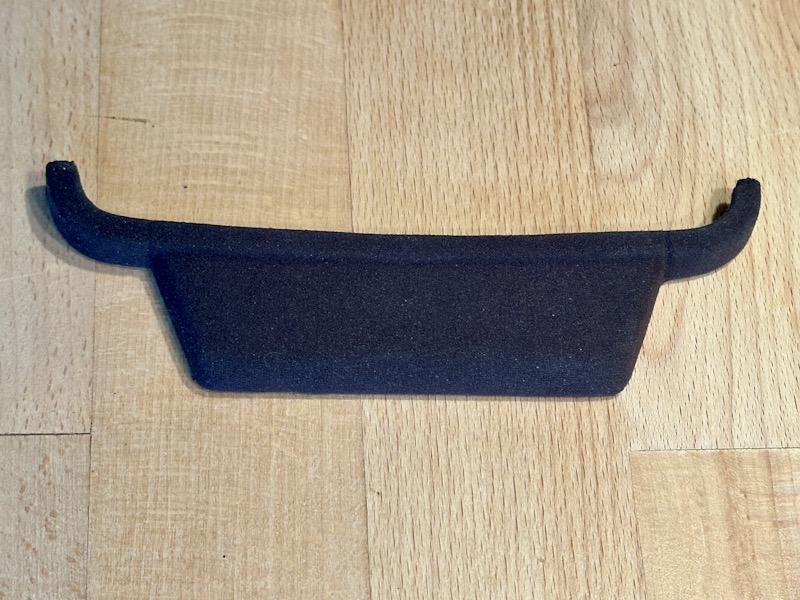
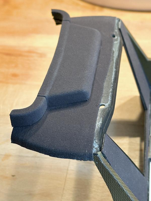
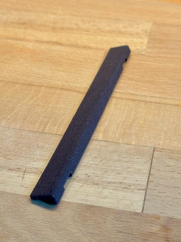
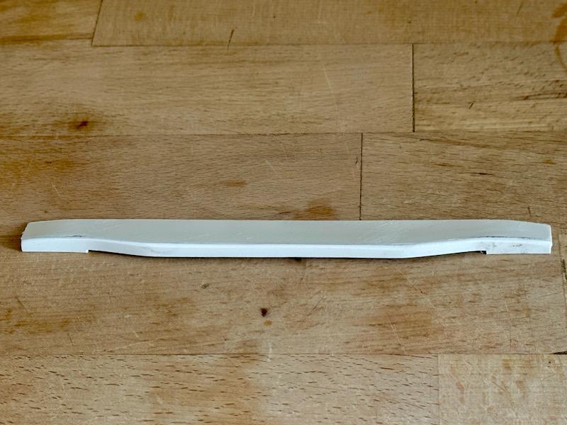
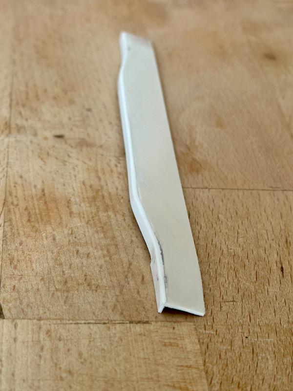
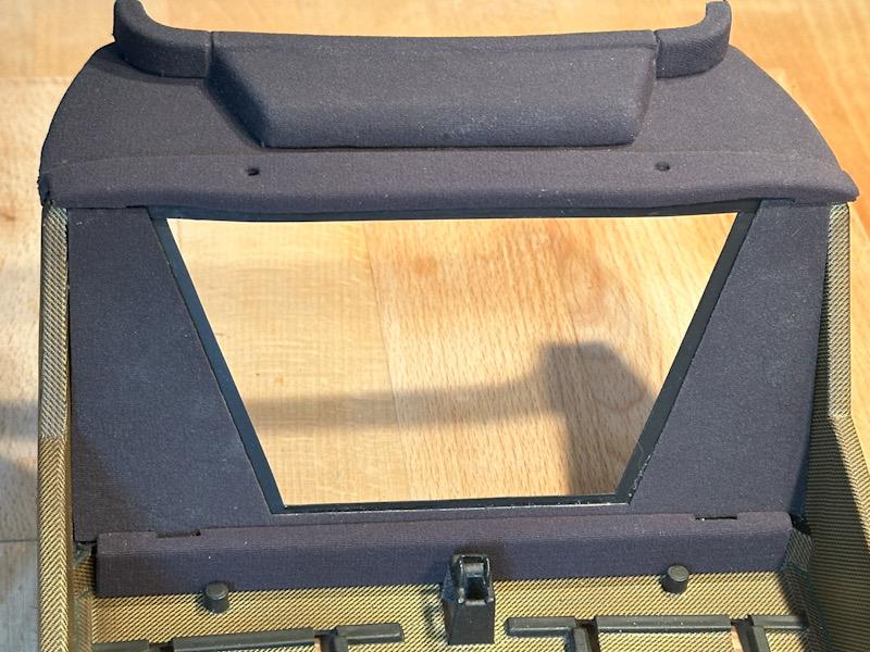
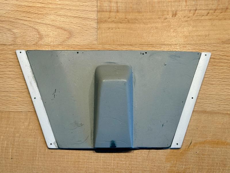
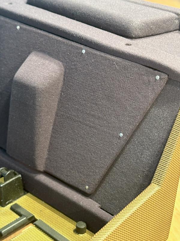
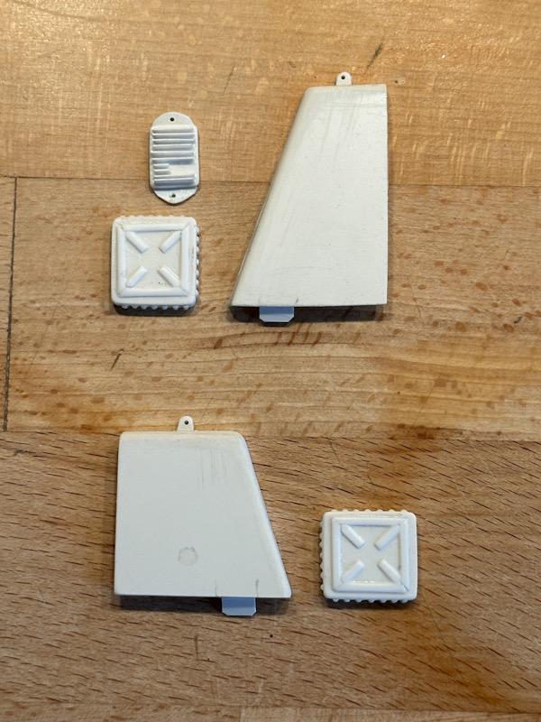
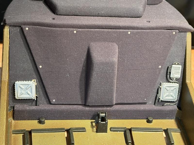
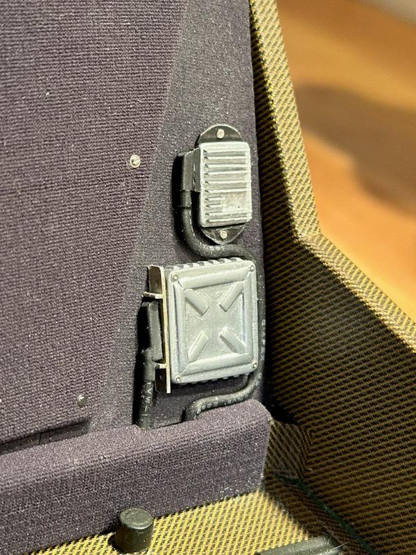
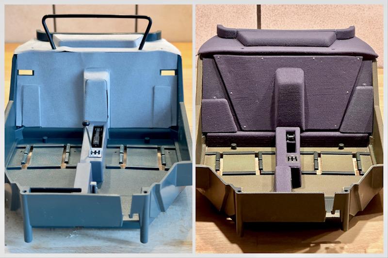
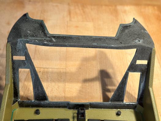
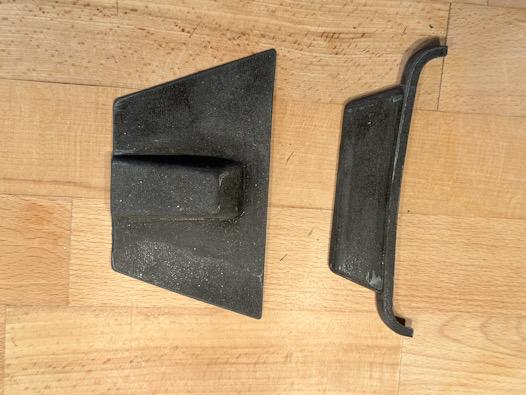
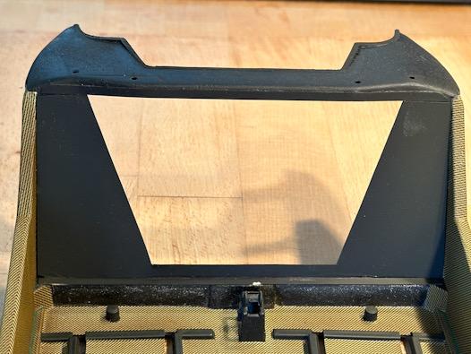
Before I finish the rear panel for the engine, the center console is still on the agenda. In the Pocher kit, the center console is one continuous piece. However, in the real F40, it's divided into two parts. To make applying the fabric easier, I split the center console just like the original. The Autograph transkit includes etched parts for the storage compartments between the gear lever and handbrake. In the original, the parts are covered with a gray felt. As described in a previous post, I'm using an anthracite gray ladies' pantyhose that closely matches the real fabric color. The color may appear distorted in the photos, but it looks better in person. After covering the parts, the storage compartment was mounted with super glue. Then I mounted the gear shift mechanism and the side footrest. Both are etched parts from the Autograph transkit. Next, I continued with the rear panel. Since the pantyhose is very flexible and tends to fray at the edges, it's not possible to cover the rear panel directly. To get a clean finish, I cut 0.1mm ABS, painted it black, and covered it with fabric. After the glue dried, I neatly trimmed the fabric at the edges with scissors. Then the covered parts were glued to the rear panel. Next, the upper window trim was covered. Before reattaching the window trim, the area underneath was directly covered. Then I made the lower trim from 1mm ABS and covered it with fabric. Next, the upper trim was made. The parts were reattached with super glue. To achieve a perfect finish, I enlarged the lid on the sides. Next, the lid was covered with fabric or a textured metal foil was applied on the back. Then the lid was screwed on with small watchmaker screws. The next step was the ECUs for the injection and their corresponding covers. I made the parts from ABS. I could have made the ECUs much more detailed with a 3D printer, but I'm very happy with the result. Especially considering that the parts are not visible when the covers are mounted. After painting the ECUs with True Metal Color and adding simple connectors and cables, the ECUs were mounted on the rear panel. Then the covers were painted black and covered with fabric. Afterwards, the covers were mounted. Similar to the original, the covers are only snapped at the bottom and screwed at the top. The center console is not yet finally installed. I still need to make the handbrake with the leather trim and the gear lever. Here's the before and after comparison. That's it for today. See you soon, Your Ferrarifan
-
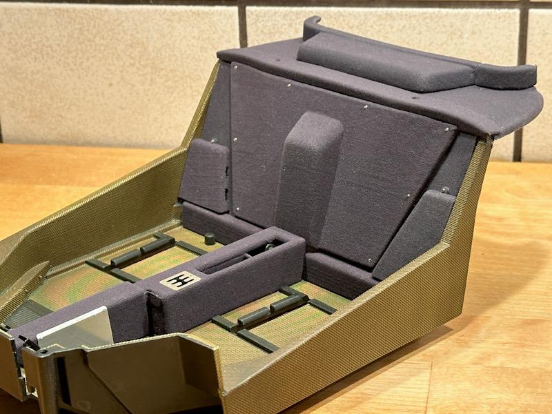
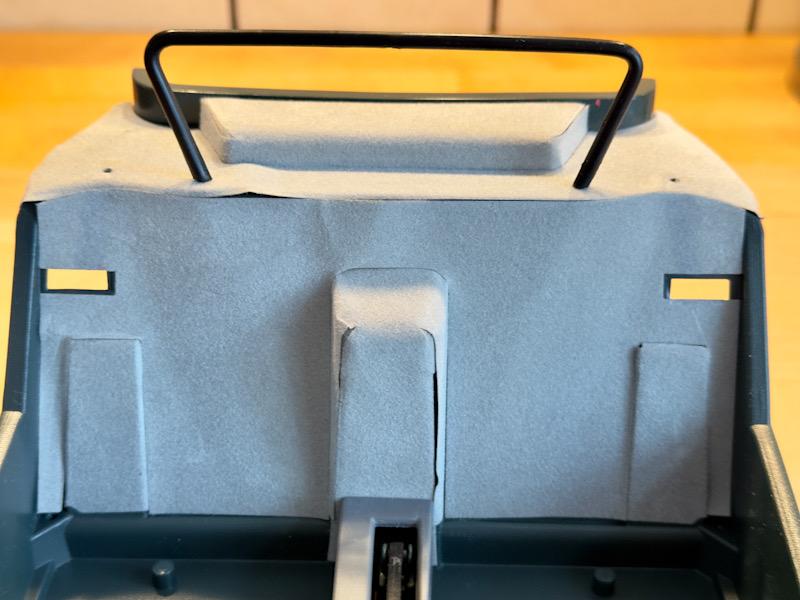
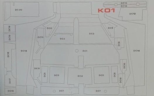
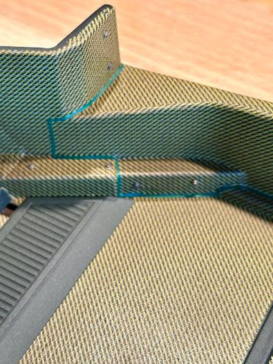
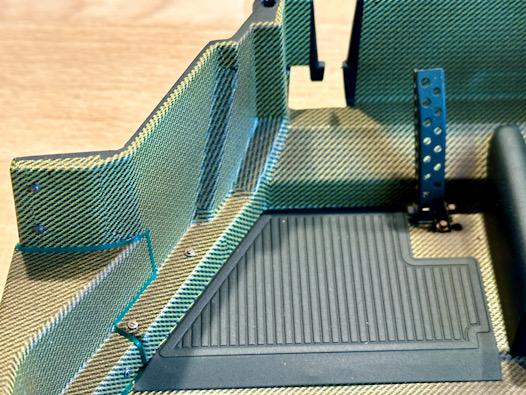
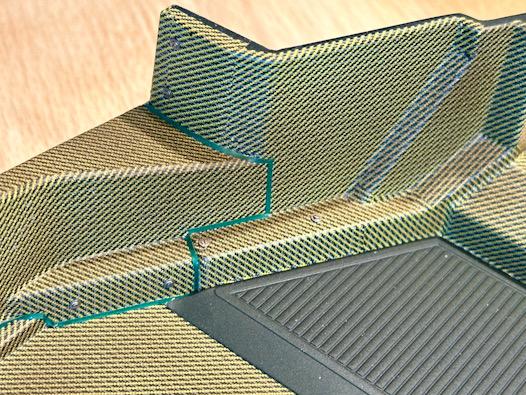
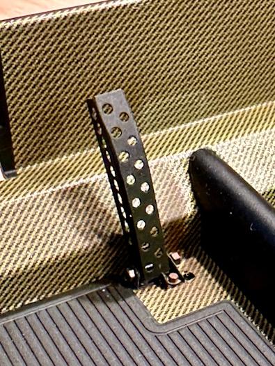
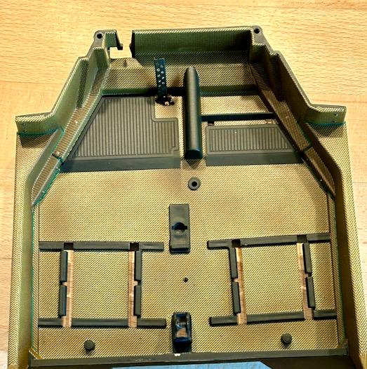
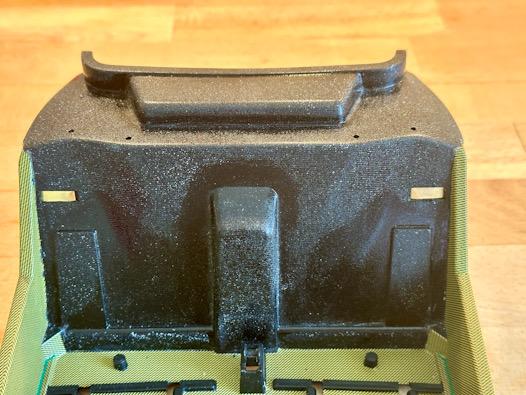
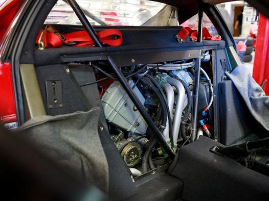
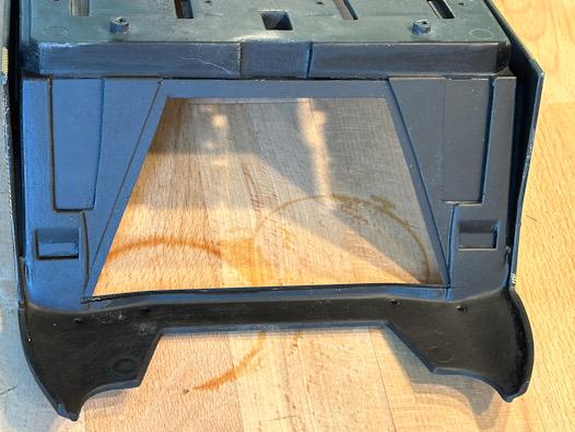
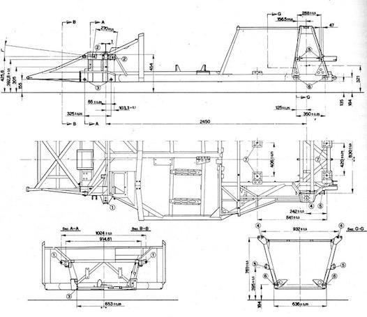
As an engineer, I want to understand how things are built and function, and as a model builder with a borderline perfectionist streak, I aim to accurately replicate every tiny detail in the model. I use Ferrari manuals available online (owner's manual, parts catalog, etc.) as sources, some of which are also included in the Autograph Transkits. Most of my time is spent on Eurospares, a British company specializing in spare parts for sports cars (Ferrari, Maserati, Lamborghini, Porsche, etc.). There, I find official drawings for parts search, which provide me with information on the overall construction and component parts. https://www.eurospares.co.uk/Ferrari/F40/F40/PartDiagrams If I need more detailed information on specific appearances, I do a Google search using the part number listed in the parts catalog. For example, if I want to know exactly what the carbon door panel looks like, I search for "Ferrari 62499800." https://www.google.com/search?q=Ferrari+…e&client=safari This way, I gather sufficient information about individual components. To get a better overview of the complete car, I go to Sotheby's, where numerous F40s are listed for sale or have already been sold. Unlike car sales platforms (e.g., Autoscout), there are many photos available there. https://rmsothebys.com/search#/?SortBy=A…aN&FromYear=NaN That's a brief overview of how I gather information. Moving on to the cockpit. The F40 is a mix of old and new technology. Its construction follows Ferrari's principle of using a steel tube frame, with the F40 featuring a progressively deformable front section to comply with global standards. However, additional reinforcements were added, and composite materials were bonded to the frame with special adhesives to achieve even greater strength. The cockpit, including the firewall, floor, and sidewalls, is entirely made of composite material and is fitted onto the frame. The basic structure of the Pocher model's cockpit matches quite well. After removing most of the covering from the rear wall, I painted the tub matte black. Then, I applied the carbon decals from the Autograph Transkit. Since there's a precise cutting pattern printed on the back of the decals, as with the seats, it was straightforward. As described above, the original cockpit consists of multiple parts glued and screwed/riveted together. Ferrari applied the adhesive in such a way that the green adhesive bead is visible on the visible side. This indicates that the F40 was designed as a race car. To represent the adhesive seams, green adhesive strips are included in the transkit. I searched for alternatives for a long time, but since I couldn't find a better solution, the adhesive seams were relocated from Autograph. Then the screws or rivets were added. Next, the accelerator pedal and the footrests were installed. Both are photo-etched parts from the Autograph transkit. Since the color of the decals is too bright compared to my reference photos, I darkened them slightly, as I did with the seats. Next up is the back wall to the engine. During my research, I found that a part of the back wall can be removed to provide direct access to the engine. Additionally, covers are mounted on the left and right sides of the back wall. Under these covers are the ECUs for the injection system. Although they are indicated in the model, their size and position are incorrect. All details that must not be missing in the model, of course. So, I simply sawed off the back wall. In the original, the entire back wall is covered with gray felt. In the model, the fabric of a gray stocking is used. To make covering easier, I also separated the upper area where the rear window is located, which is also an additional part in the original. Furthermore, I removed the two incorrect covers. Then I made a back wall from 0.1mm thick ABS, creating an overhang for the middle cover and simultaneously closing the openings of the incorrect ECU covers. That's it for today. Next time, the area will be completed. See you soon, Your Ferrarifan