
Ira
-
Posts
7,265 -
Joined
-
Last visited
Content Type
Profiles
Forums
Events
Gallery
Everything posted by Ira
-
 Thanks Tony! So glad you enjoyed it...
 -
1/16 Scale Army Vega Funny Car - Finished 10/14/2018
Ira replied to Mooneyzs's topic in WIP: Drag Racing Models
Great Project Chris! Beautiful Work... -
Great Project! Love the Pacers...
-
Thanks Chris! The sure are Quick Change Rear End Halves. There is also 2 Carb Halves on the bottom...
-
Strobe Lights! There are 3 Strobe Lights on the Underside of the Body. They all go on & off together because they are controlled by the Circuit Board. This Lighting set up plugs into the wall and converts to DC, it also be done with a 9 volt battery enclosed in the Body. That's All Folks! Hope you enjoyed the VooDoo Raider...
-
Amidships Housing Lights! The Yellow Lights make the Brass Screen Glow like its Super Hot! More Coming...
-
Mountain Mover
Ira replied to hobbybobby's topic in WIP: All The Rest: Motorcycles, Aviation, Military, Sci-Fi, Figures
Great Build Bobby! Love the Painting & Details... -
Pulsing Engine Lights! The Engine Lights Pulsate from Lite... To Bright! More Coming...
-
Thanks Joe! No Problem. VooDooFX is very good to me. Randy at VooDoo is the Best....
-
Thanks Bob! I'm thinking about Metalflake Purple with Silver & Gold accents...
-
Thanks Tony!
-
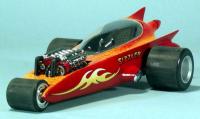
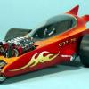
VooDoo RAIDER is Finished! After carefully checking the Wires and making sure they weren't getting in the way, I glued the Body Halves together. Then I glued the last few parts in place, did some Touch-Up Painting and Tested the Lights again. All the Lights Work Great! Thank You Randy at VooDooFX! Here are some Finished Photos, hope you enjoy them. The first photo shows the 17" wide Mobius Cylon Raider on the left and next to it my modified Monogram Cylon Raider. Headlights! More Coming...
-
Turn on the Lights! Here are the Bottom and the Top of the Raider, ready to be Wired together. The White (Positive) Wires are attached the Red (Positive) Power Plug Direct Wire. The Black Wires are attached the Black Power Plug Wire. Those were the last Wires! Every Wire was tested before soldering. The next step is to carefully fit the Top & Bottom of the Raider and glue it together. Then Final Touch-Up & Detailing are all that is left to do. I hope to have finished Photos with Lights Tomorrow. Finished Photos Coming...
-
More Vents! I decided to leave the Cut out areas open except at the ends. I cut a small piece of plastic strip to fit each end and glued them in place. Next I carved out the areas behind the 3rd Engine and filed them down smooth. Then I cut 2 pieces of plastic strip and glued them in the ends of the slots as shown. More Coming...
-
Top Lights! First I cut 2 small pieces of Fine Mesh Brass Screen. Then I squeezed and shaped the Screen over the end of a dowel. The Brass Screen holds the round shape and it holds itself in place inside the Amidships Housings Light Cavity. The Lights create a Great effect shinning through the Screens. Here are the Forward Cabin and the Amidships Housings in place. The Light Wires are run through the Holes I made in the Body for them. More Coming...
-
Top Side! I soldered long Wires to the Headlights and the Housing Lights and then covered the solder joints with Heat Shrink Tubing. I drilled 2 Holes in the Body under the Forward Cabin, close to the posts, for the Headlight Wires. Next I drilled 2 Holes in the Body, Directly under the Housing Lights. More Coming...
-
Strobe Wings! First I glued the Wing Halves together. Then I glued the Wings to the bottom half of the Body. Next I attached the White Wing Wires to the Red Power Wire with the other White Wires. I soldered the connection with all of the White Wires together. I attached the 2 Black Engine Wires to the Top Black Wire from the Board. The 3 Black Strobe Wires are attached to the bottom Black Wire coming from the Board. I tested all of the connections with a 9 volt battery, before soldering. If you hook up the Strobe or Engine Lights to the wrong lead they wont work. Next I soldered the connection with all of the Black Wires together. All of the connections were then covered with Black Tape or Shrink Tubing. I also added Black Tape to hold the lights in if the glue fails. Here is the bottom of the RAIDER with all of the FX Lights Wired to the Board. Notice the 2 unconnected Red and Black Wires in the bottom left of the photos. These 2 Wires are the Power Wires for the Headlights and the Amidships Housing Lights. They are mounted in the top of the Body. More Coming...
-
Thanks for the kind words John! It was Great seeing you a NNL West...
-
More Lights and More! This is Diffusion Material for the Engine Lights. It comes in many Textures & Colors to make the LED Light look more Exciting and Realistic. I cut 2 pieces about the size of the Engine Back Plates. Here is the Diffusion Material glued in place behind the Engine Exhaust Cone in the bottom half of the Body. The 3rd Strobe Light has also been glued in place, with the Wires wrapped around the post. The AC Power Supply Plug has been installed too. Next the 2 Engine Lights were attached to strips of plastic to position them in the middle of the Engine Exhaust Cone. Then long Wires were added to all of the Lights. I made a quick simple diagram showing positions of the Lights, Board & Power Supply. This made it much easier to keep track on things. There are 2 Red Wires and 2 Black Wires coming from the Power Plug. One Red Wire goes to the Red Wire on the Circuit Board and one of the Black Wires from the Power Plug goes to the Black Wire on the right side of the Board, right next to the Red Wire that I just connected. The White, Positive Wires from the Strobe and Engine Lights attach to the Red Power line I just connected to the Board. I used small lengths of plastic tubing glued inside the Body to hold some of the Wires in place. More Coming...
-
Thanks Janne! I really enjoy John Teresi's work too, he is a Great Builder...
-
Hot Glue! Please read all instructions and Warnings about all products mentioned, before using them. I'm using a Hot Glue Gun to glue the Lights in place. The Headlights fit in 2 Holes drilled through the Forward Cabin & the Front Bulkhead Detail. The Yellow Lights go in the drilled Holes in the Amidships Housings. Next I Hot Glued in 2 Strobe Lights in the Under Wings. I needed to bend the LED leads over to fit in the Wing. If you try to bend the Leads right at the Base Line you may damage the LED. So using Needle-Nose Pliers I held the Leads tight at the LED Base and bent the Leads over the ends of the Pliers. I added wires long enough to easily reach the Circuit Board too. Then I covered the solder joints with Shrink tubing. More Coming...
-
Thanks Joe! Yeah, these VooDooFX Lighting Kits make it easy to add all kinds of Lights...
-
Resistance! I need to add resistors to all of the different types of Lights. I keep the different lights in separate baggies so they don't get mixed up. Always add the Resistor to the Positive lead. The Positive Lead is the Long one. I start by bending the Positive Lead out to make it easier to work on. Then I twist one end, either one it doesn't matter, of the Resistor around the Positive Lead. Next I soldered the Resistors to the Lights and cut off the excess wire or lead. Then I slipped on some Shrink Tubing. Next I heated up the Shrink Tubing with a Lighter. More Coming...
-
Great Progress!
-
More Power! I decided to replace the Rear Cap with another Jet Engine. I found this one in the Airplanes Part Box. I glued this Engine Section in place and molded it in. More Coming...