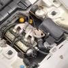
Foxer Posted December 26, 2009 Posted December 26, 2009 (edited) The boys down at the local Sunoco station just got too excited building this comp coupe to run out on the left coast at the last run at Lion's and measured only ONCE! The engine is set too far back when matching the bell housing to have the rear header clear the body. It looks like at least a 1/4" interference. The headers will be straight zoomies tilted back. The obvious solution is to move the engine forward at least a 1/4" which is no problem as far as fitting to the frame. The space between the firewall/bell housing will become a problem as far as looking correct. I don't believe it's practical to move the bell housing at this late stage. Maybe attach the bell housing from the original engine will make it look "ok". This is a Competition Parts Pack engine and the housing is here. The rear header is pretty much in line with the magneto. It's also possible to notch the body and paint at this point, though this may just look TOO funky. So, I'm reaching out to any ideas however funky they may be. Edited December 26, 2009 by Foxer
dwc43 Posted December 26, 2009 Posted December 26, 2009 Run them like a pair of zoomies that I run on my old dirt track car. The real ones are 18" long with no collector. They turn straight down at the head, but angle toward the rear of the car and have an angle cut on the very tip or outlet of each tube. Looks like you have room to run them from the head, on the outside of the frame and between the body work. You just wont be able to see the rear tubes all that well once assembled but it will look correct. You can make them out of solid core solder and drill the openings at the tips. Should look pretty good to me.
Foxer Posted December 26, 2009 Author Posted December 26, 2009 Run them like a pair of zoomies that I run on my old dirt track car. The real ones are 18" long with no collector. They turn straight down at the head, but angle toward the rear of the car and have an angle cut on the very tip or outlet of each tube. Looks like you have room to run them from the head, on the outside of the frame and between the body work. You just wont be able to see the rear tubes all that well once assembled but it will look correct. You can make them out of solid core solder and drill the openings at the tips. Should look pretty good to me. I smell some potential here .. but might have only about 12" for length .. still..
dwc43 Posted December 26, 2009 Posted December 26, 2009 That might be all you need. After all my car was a real one running those 18" pipes and that is what that engine package liked. It was a 365 flat top 11:1 with hyd. cam cast intake 2" 4 hole spacer with an 850 Carter Thermoquad on it and 1 5/8 tube 18" long custom made zoomies. BAcked by a 3 speed and an 8 3/4 rear axle with a final drive ratio of 6.49:1 in a 3250 lb car. I know it's a model, but it's supercharged, so check the tube size and length on them. You can always put more angle to it to run a longer tube and change the angle cut on the exit of each tube. By the way, if you have never seen a 1:1 car with zoomies facing the ground it's something else. We had a gravel drive in front of the shop and I'm bad about pulling it outside and working in the sun on a good day. Fire it up in the gravel and it would leave a hole about the size of my laptop and about 4 in. deep in the drive. They kick up a lot of dust at the race track too. Might keep that in mind if you are one that likes to do weathering on your cars. Some dirt or light dust around the ex. area would look real.
Foxer Posted December 26, 2009 Author Posted December 26, 2009 This is sounding really good! Those driveway holes are a riot! .. that had to be one powerful leaf blower!! Looks like I need to find some .092 solder.. the .062 I have will just look too small for this. I was gonna use some alum tube but the bend-ability of the solder may be a must, especially with the short time I had left. Thanks for the first hand knowledge .. I'm getting excited now..
dwc43 Posted December 26, 2009 Posted December 26, 2009 Welcome, anytime. Aluminum tubing might work. You really only have one bend at the head area for all 8 cyl. Getting the angle cut at the exit to match on all 8 might be a problem though. Here's a pic of some Boom Tubes for inspiration. These are actually sprint car headers for a chevy engine. If you want to look at ex. headers and race mufflers and such check out www.speedwaymotors.com and www.stockcarproducts.com and www.drgas.com I've run stuff on several of my race cars from all three of these companies. Good reference pics but only for carb and some injection for sprints from Speedway. Yeah, refilling the drive way potholes was a pain, but I always got a laugh out of it too. Just think what it did to the dirt in the pits. That's why most places wont let you run them facing the ground. Most will let you run the boom tube type though.
Foxer Posted December 26, 2009 Author Posted December 26, 2009 Looks like the Comp Coupe will be sweeping the pavement .. free of charge! I went a bit off kilter as far as headers go since I started fabricating out of some 18 gage wire I had and similar in fashion to what dwc43 has said. The insulation has an OD of .072", or 1.8" diameter and looks about right. They are a tight fit on the Competition Pack 283 as far as also fitting a flange around them. I pulled back the wire from the end and the insulation makes a node end when cut square. Some aluminum metalizer is now drying on them. They will bent easily once glued into the block holes. They will bend down and back slightly so the rear ones exit under the body. Even if these have to bend a bit more than the exposed ones, I'm guaranteed a fit. Length should scale out about 15".
dwc43 Posted December 26, 2009 Posted December 26, 2009 Glad to hear it's working out for ya. Post up a pic when your done. I'd like to see the finished product. I have that same parts pack full of engines too.
Foxer Posted December 27, 2009 Author Posted December 27, 2009 Tomorrow, when the header paint is dry, I should know that's it's gonna work for sure and will throw some pics here. The WIP for the car is throughout the Lion's drag strip build off here. The link is to the current last page. This build has been going on since April and ends Dec 31 ..of course I'm right down to the wire, but MAY make it!
dwc43 Posted December 27, 2009 Posted December 27, 2009 I looked over the last page of that build off. If you can, when you get through with it, I'd like to see a pic of those pop off valves you made out of bolts and wire for the blower. I may try to make some for some other projects down the road. Is that chassis from that Cuda and I think Challenger digger kit? I've been thinking about picking up a couple of them to do some open body type rail cars of the past. Looks good so far. I think you can get it finished too.
Foxer Posted December 27, 2009 Author Posted December 27, 2009 The chassis is from the Hemi Cuda. Most everything I used is from that kit as it was the right wheelbase and was fairly realistic for a 62-63 car. The pop off valves are made from some HO scale bolts I had for ages. They are square nuts and have large washers. I used because the washers gave a large end for the springs. The wire is stripped Radio Shack wrapping wire, .001" diameter and silver .. just wrapped around the end of a drill bit slightly larger than the shaft on the bolts. It ended up being a pretty simple job and should add a lot to the plain disk in the kit. Those I plan to do some closeups.
dwc43 Posted December 27, 2009 Posted December 27, 2009 Good to know. I might pick up one of those and use it to build a car then. I also wonder if the throttle springs from model car garage would work with those bolts or if they are too big. I have some around here somewhere. I might have to experiment with them and see what they look like.
dwc43 Posted December 27, 2009 Posted December 27, 2009 Good to know. I might pick up one of those and use it to build a car then. I also wonder if the throttle springs from model car garage would work with those bolts or if they are too big. I have some around here somewhere. I might have to experiment with them and see what they look like.
Foxer Posted December 27, 2009 Author Posted December 27, 2009 I also wonder if the throttle springs from model car garage would work with those bolts or if they are too big. I have some around here somewhere. I might have to experiment with them and see what they look like. I'd expect they may be close, but making springs of any size from wire is so easy .. and about as cheap as it gets. I use wire for throttle and shock strut springs too.
Foxer Posted December 28, 2009 Author Posted December 28, 2009 Here's the blow-off valve done. These extreme close ups really give you something to study for improvement next time around! The headers worked out fine.. they'll look ok. Still one this side I had to replace due to length.
dwc43 Posted December 28, 2009 Posted December 28, 2009 Thanks for the pics. If you have time and can put a little angle cut on the exit of the tube it may look better. Just a thought.
Foxer Posted January 2, 2010 Author Posted January 2, 2010 Thanks for the pics. If you have time and can put a little angle cut on the exit of the tube it may look better. Just a thought. I've defiantly been thinking about that angle cut and completely agree it will look good. I'm not sure I've left enough insulation on the wire to allow it, but it probably won't matter too much if the wire ends up close to the ends as I't impossible to see. If I think I can still do it without screwing things up I will
dwc43 Posted January 2, 2010 Posted January 2, 2010 Cool. Just point me to a pic when you get it all finished up. I'd like to check it out.
Recommended Posts
Create an account or sign in to comment
You need to be a member in order to leave a comment
Create an account
Sign up for a new account in our community. It's easy!
Register a new accountSign in
Already have an account? Sign in here.
Sign In Now