southpier Posted February 26, 2015 Share Posted February 26, 2015 anyone know the type of engine and (2-part question) the suitability of adapting it? snipped from this page: http://www.larrygscale.com/MOTOR-BLOCK-STRAIGHT-6-CIRCA-20S_p_36.html thanks Quote Link to comment Share on other sites More sharing options...
chunkypeanutbutter Posted February 26, 2015 Share Posted February 26, 2015 Looks to be a diesel engine, maybe from a small switcher locomotive? Quote Link to comment Share on other sites More sharing options...
Fabrux Posted February 26, 2015 Share Posted February 26, 2015 No idea what it is, but it sure looks neat! Quote Link to comment Share on other sites More sharing options...
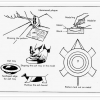
Longbox55 Posted February 26, 2015 Share Posted February 26, 2015 I'm inclined to think it's a made up engine, rather than an actual replica. I'm pretty sure it's not a Diesel, it's too small for a Diesel engine of that era. I also don't see any sort of injector setup, or really an intake at all. Definitely an L head, so there should be an intake on the same side as the exhaust. The piping on the top looks to be the water manifold. It would be nice if there were more pictures of it on the site, and perhaps the manufacturer name of whoever made the replica. Quote Link to comment Share on other sites More sharing options...
Ace-Garageguy Posted February 27, 2015 Share Posted February 27, 2015 (edited) I could be wrong, but I tend to agree with Bill's (Longbox55) take on this thing. It looks to me as though someone has taken random parts from various sources, without really understanding their functions, and has combined them in a way that looks old-timey engine-ish...sorta. If you go to the link and click on the photo, an enlarged version opens. There is a line of what appear to be exposed valve springs facing the camera behind the manifold-looking thing. This would indicate all the valves are in-block, in a single-file line. In a real engine, this valve arrangement would necessitate both intake and exhaust ports and manifolding to be on the same side of the engine, as noted above. I see nothing on this model that's readily identifiable as either intake or exhaust manifold. The plumbing on top of the head does appear to be coolant-related, as does the horizontal chrome piping connected to what appears to be a coolant pump, driven from a horizontal jackshaft. I think it's a bogie., but I'm still hunting. Closest I've found so far is this old 2-stroke Roberts aircraft engine. Somewhat similar water piping on top, but this engine breathes through ports in the cylinder walls and would have no need for valves or springs indicative of poppet-valves as on the model shown in the OP. Edited February 27, 2015 by Ace-Garageguy Quote Link to comment Share on other sites More sharing options...
Art Anderson Posted February 27, 2015 Share Posted February 27, 2015 I could be wrong, but I tend to agree with Bill's (Longbox55) take on this thing. It looks to me as though someone has taken random parts from various sources, without really understanding their functions, and has combined them in a way that looks old-timey engine-ish...sorta. If you go to the link and click on the photo, an enlarged version opens. There is a line of what appear to be exposed valve springs facing the camera behind the manifold-looking thing. This would indicate all the valves are in-block, in a single-file line. In a real engine, this valve arrangement would necessitate both intake and exhaust ports and manifolding to be on the same side of the engine, as noted above. I see nothing on this model that's readily identifiable as either intake or exhaust manifold. The plumbing on top of the head does appear to be coolant-related, as does the horizontal chrome piping connected to what appears to be a coolant pump, driven from a horizontal jackshaft. I think it's a bogie., but I'm still hunting. Closest I've found so far is this old 2-stroke Roberts aircraft engine. Somewhat similar water piping on top, but this engine breathes through ports in the cylinder walls and would have no need for valves or springs indicative of poppet-valves as on the model shown in the OP. Ya know, it could also be a 4-valve T-head engine! On the T-head design, intake valves are on one side of the block, exhaust on the other side--not an uncommon engine design a century ago. Art Quote Link to comment Share on other sites More sharing options...
Ace-Garageguy Posted February 27, 2015 Share Posted February 27, 2015 (edited) Ya know, it could also be a 4-valve T-head engine! On the T-head design, intake valves are on one side of the block, exhaust on the other side--not an uncommon engine design a century ago. Art Good call, Art ! This is a 3-cylinder, 4-valve (per chamber) T-head ('20-'26 American LaFrance) with the line of exposed valve springs like the OP pic, similar coolant plumbing...many things in common with the OP design. This is the other side. Zo, the OP pic appears to be at least a somewhat viable design for a large displacement, slow-revving engine of the early 1920s...depending of course on what the other side looks like. Here's another somewhat similar design, a Teetor inline 6-cylinder T-head engine. Edited February 27, 2015 by Ace-Garageguy Quote Link to comment Share on other sites More sharing options...
southpier Posted February 27, 2015 Author Share Posted February 27, 2015 i do believe the site i found this was a source for model railroading accessories. despite their reputation for 'rivet counting', there's probably a 90% membership that will accept a 'plausible' solution. can't say either is right, but it's interesting to see how different people view things. Quote Link to comment Share on other sites More sharing options...
Ace-Garageguy Posted February 27, 2015 Share Posted February 27, 2015 i do believe the site i found this was a source for model railroading accessories. despite their reputation for 'rivet counting', there's probably a 90% membership that will accept a 'plausible' solution. can't say either is right, but it's interesting to see how different people view things. I seem to recall that many train guys get pretty intense over actual railroad rolling stock and locomotives, but not so much about scenery and load items. Seeing as how this is G-scale stuff, which commonly mixes slightly off-scale bits (HO was still pretty prototype-correct last time I looked) it's not that surprising if this isn't a representation of an actual engine. Quote Link to comment Share on other sites More sharing options...
Art Anderson Posted February 28, 2015 Share Posted February 28, 2015 Good call, Art ! This is a 3-cylinder, 4-valve (per chamber) T-head ('20-'26 American LaFrance) with the line of exposed valve springs like the OP pic, similar coolant plumbing...many things in common with the OP design. This is the other side. Zo, the OP pic appears to be at least a somewhat viable design for a large displacement, slow-revving engine of the early 1920s...depending of course on what the other side looks like. Here's another somewhat similar design, a Teetor inline 6-cylinder T-head engine. Actually, Bill...... That's a SIX cylinder ALF engine. It has three "two cylinder" blocks, on a common crankcase, but it's a perfect example of a T-head engine: Intakes on one side, exhaust outlets on the opposite side. Art Quote Link to comment Share on other sites More sharing options...
Ace-Garageguy Posted February 28, 2015 Share Posted February 28, 2015 (edited) Actually, Bill...... That's a SIX cylinder ALF engine. It has three "two cylinder" blocks, on a common crankcase, but it's a perfect example of a T-head engine: Intakes on one side, exhaust outlets on the opposite side. Art Oops. Yup, you're right. So only 2 valves per cylinder. My duh. Edited February 28, 2015 by Ace-Garageguy Quote Link to comment Share on other sites More sharing options...
gtx6970 Posted March 3, 2015 Share Posted March 3, 2015 Good call, Art ! This is a 3-cylinder, 4-valve (per chamber) T-head ('20-'26 American LaFrance) with the line of exposed valve springs like the OP pic, similar coolant plumbing...many things in common with the OP design. This is the other side. Zo, the OP pic appears to be at least a somewhat viable design for a large displacement, slow-revving engine of the early 1920s...depending of course on what the other side looks like. Here's another somewhat similar design, a Teetor inline 6-cylinder T-head engine. How many spark plugs that thing have? I know it's not uncommon for emergency equipment engines from that era to have multiple ignition systems....but I've never seen 3 per cylinder if this is in fact a 6 cylinder Quote Link to comment Share on other sites More sharing options...
Recommended Posts
Join the conversation
You can post now and register later. If you have an account, sign in now to post with your account.
Note: Your post will require moderator approval before it will be visible.