Goodwrench3
-
Posts
804 -
Joined
-
Last visited
Recent Profile Visitors


Goodwrench3's Achievements
MCM Ohana (6/6)
-

AMT "Miller" GMC Astro 95
Goodwrench3 replied to Goodwrench3's topic in WIP: Model Trucks: Big Rigs and Heavy Equipment
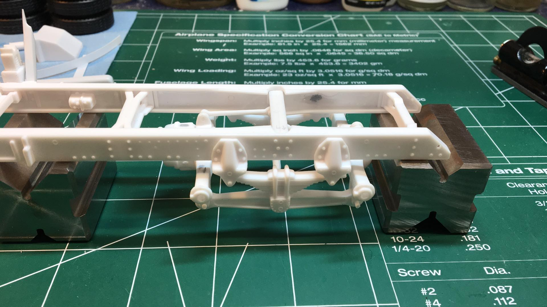
Hi -- Well, not much -- I guess you could say "life happened". LOL. I got real busy at the end of last year and then I retired. BUT -- This build is the "poster child" for a steel build/alignment board that our club is producing. We've been selling them at our annual show (Midwest Scale Madness in Ft. Atkinson, WI) and at the Detroit spring shows (and a few others). But we needed a "demo" for the build/alignment board so that people could see how it is used to "square" and align everything while building these kits. And this build became the "demo" for it. I'll post a photo of it here tomorrow so you can get an idea of what it looks like. It will be finished this summer (hopefully), but it was "called into service" for this purpose in the mean time ! Thanks ! -
Hi -- Thanks for your interest. I have not done work like that for others to date. I'm not saying it's "off the table", just that I have barely had time to build for myself with work, etc. I'm retiring in a couple of weeks, so that might change things for me. But beyond that, I'd have no idea what guys charge to do builds for people. That one in the photo had probably 50 to 70 hours into it. It's close to "box stock", but very clean.
-
Thanks for that video. Yeah -- the more I look at it, the orientation of the steering box looks OK compared to the video. I think what probably needs to be done is to cut the shaft part off and re-orient it to mate with the cab floor correctly. I don't think the steering box itself can be rotated enough -- and probably shouldn't be. Where it is now is pretty much like the one in the video.
-
Thanks -- I'll take a look.
-
I tacked the steering box on, but I think it needs to be "rotated" more counter clock-wise so that the shaft is more forward where it meets the cab floor. The steering shaft would come down I think right at the front of the tub floor.

-
Thanks for posting the photo. That helps a lot. I'll try tacking mine in that position and then see how it works with the cab lowered. I'm guessing there's some trimming to be done.
-
Am I on the right path here ? Best I can tell from the instructions -- it looks like the short leg of the pitman arm goes upward. Now part #7 is the mystery for me.
-
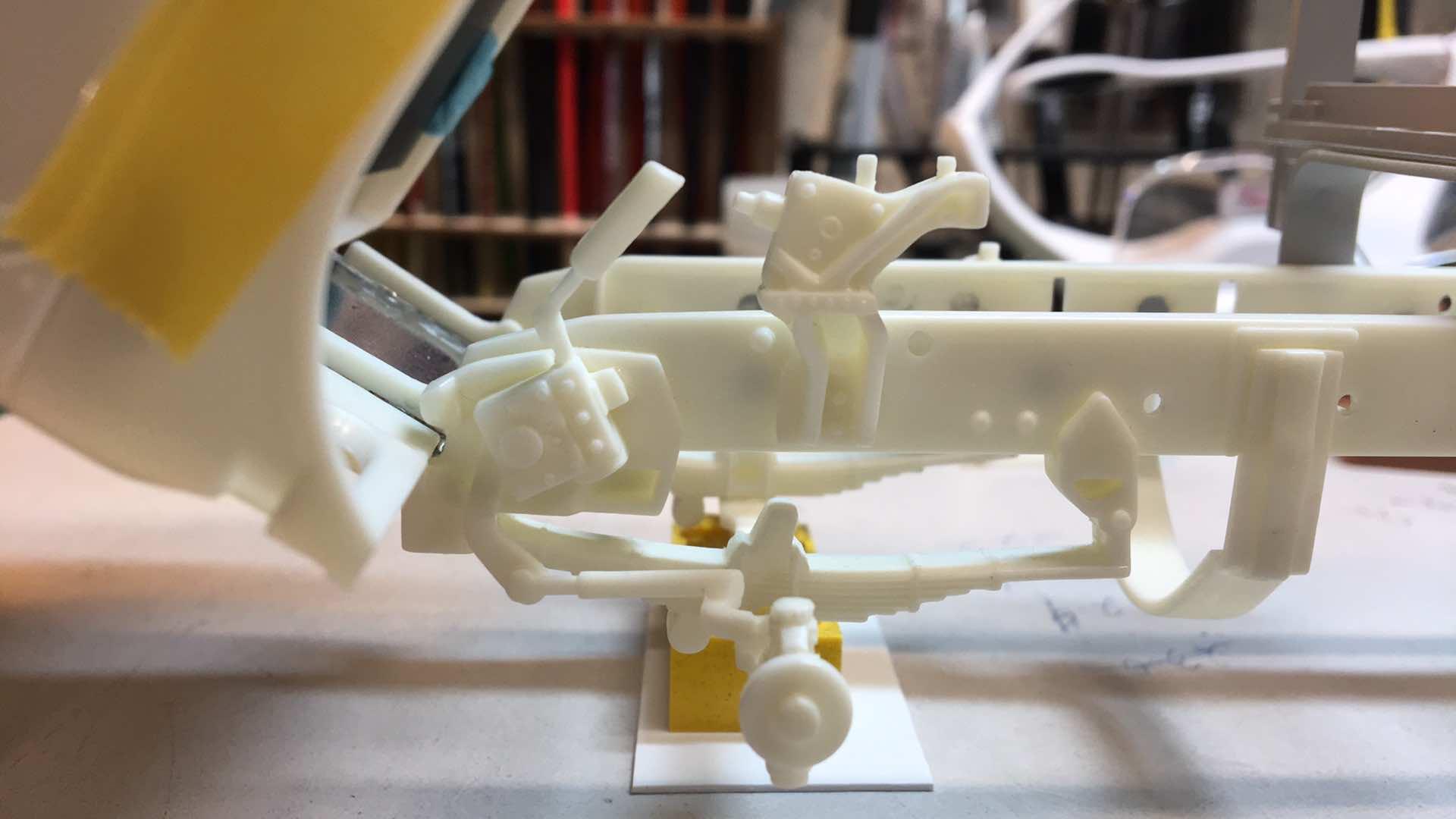
Hi all: I need some help on the steering box installation. The instructions are vague and I haven't been able to find any photos of this installed on the frame or any 1:1 photos to go from. It's parts 5, 6, and 7. I don't see a positive attachment location on the spring mount ? Would love some photos of your builds showing this area. Thanks!
-
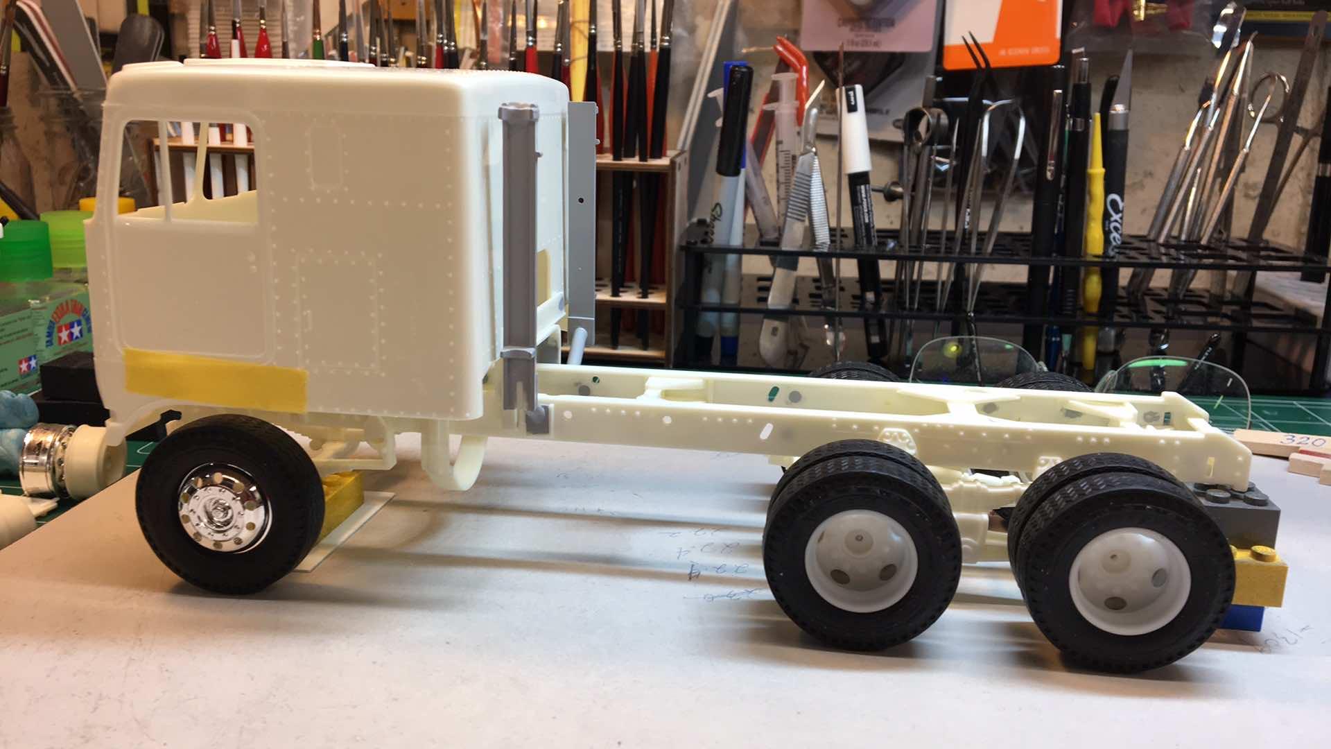
Well, after a long "pause", I'm back on the job with this one. I changed direction on the drive wheels -- these are 3D printed ones that work perfectly with the kit Goodyear 10.00-20 tires. Test fitted the cab today -- making sure the shift tower lands somewhere close to the cab floor opening.
-
AMT "Miller" GMC Astro 95
Goodwrench3 replied to Goodwrench3's topic in WIP: Model Trucks: Big Rigs and Heavy Equipment
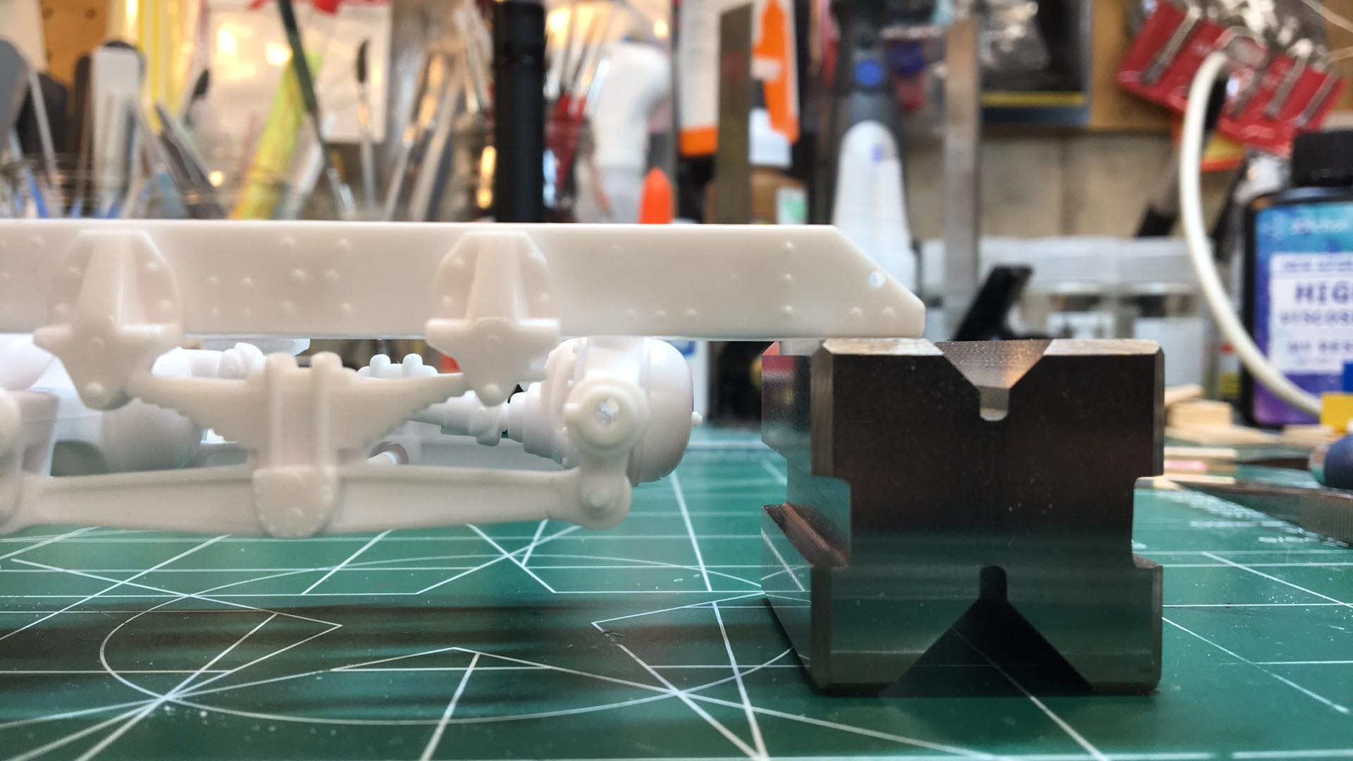
Hi -- what are these ? " 1-2-3 blocks and a set a precision parallels. " ?? Can you send me a link for these ? Thanks ! -
AMT "Miller" GMC Astro 95
Goodwrench3 replied to Goodwrench3's topic in WIP: Model Trucks: Big Rigs and Heavy Equipment
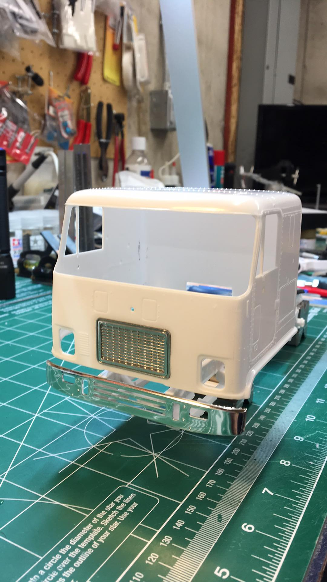
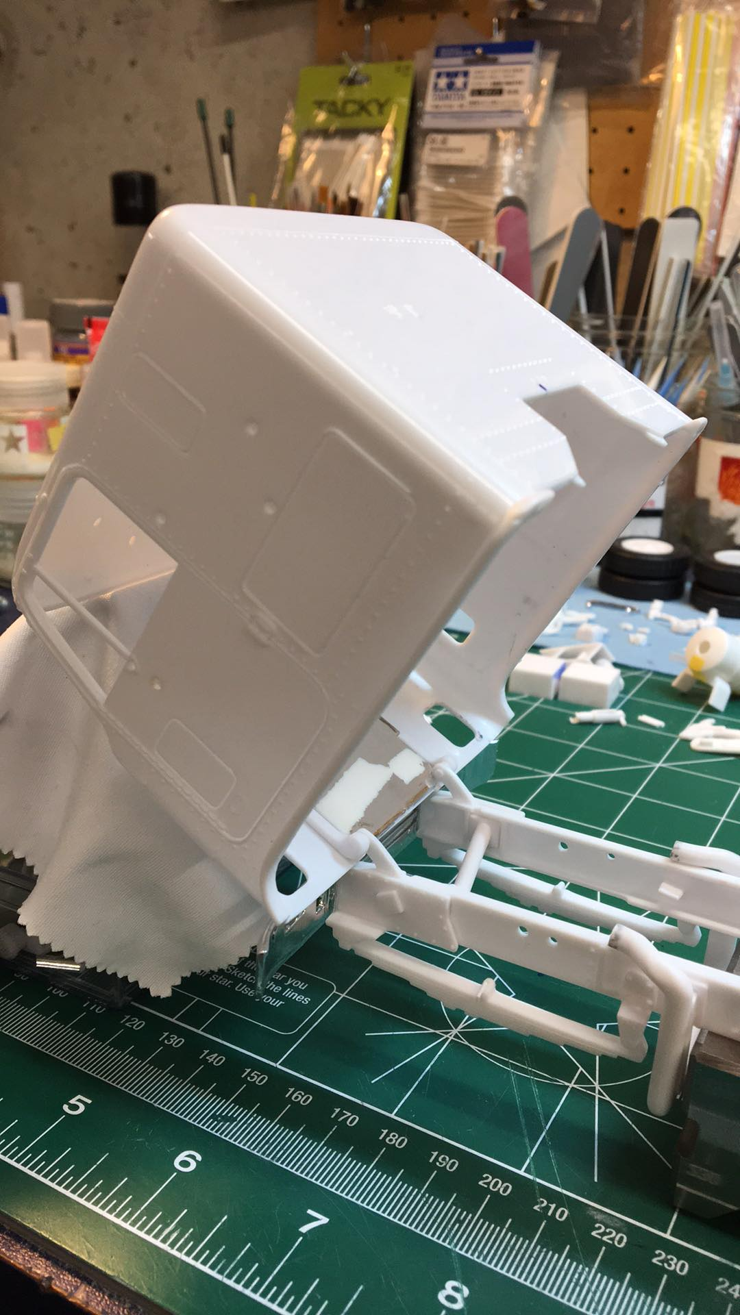
This weekend I was able to finally "tack" the hinges in place and make sure the cab tilted with the bumper on and did not have any binding/clearance issues after lowering the cab. Big win ! I will probably need to move the bumper up a bit when it's finally assembled. I also got the front torque rod adjusted so the rear axles are better oriented and the center drive shaft fits right.
-
AMT "Miller" GMC Astro 95
Goodwrench3 replied to Goodwrench3's topic in WIP: Model Trucks: Big Rigs and Heavy Equipment
Agreed. It didn't "smell right" to me. I've been trying to find a 1:1 photo of an Astro 95 with a Hendrickson suspension to try to see angle of the axles and the torque rods, but I haven't been able to find any yet. -
AMT "Miller" GMC Astro 95
Goodwrench3 replied to Goodwrench3's topic in WIP: Model Trucks: Big Rigs and Heavy Equipment
I think the rear torque arm is probably OK ? I would expect the rear axle to be "canted" back a bit like it is to make the drive line between the front and rear axle more of a straight line. -
AMT "Miller" GMC Astro 95
Goodwrench3 replied to Goodwrench3's topic in WIP: Model Trucks: Big Rigs and Heavy Equipment
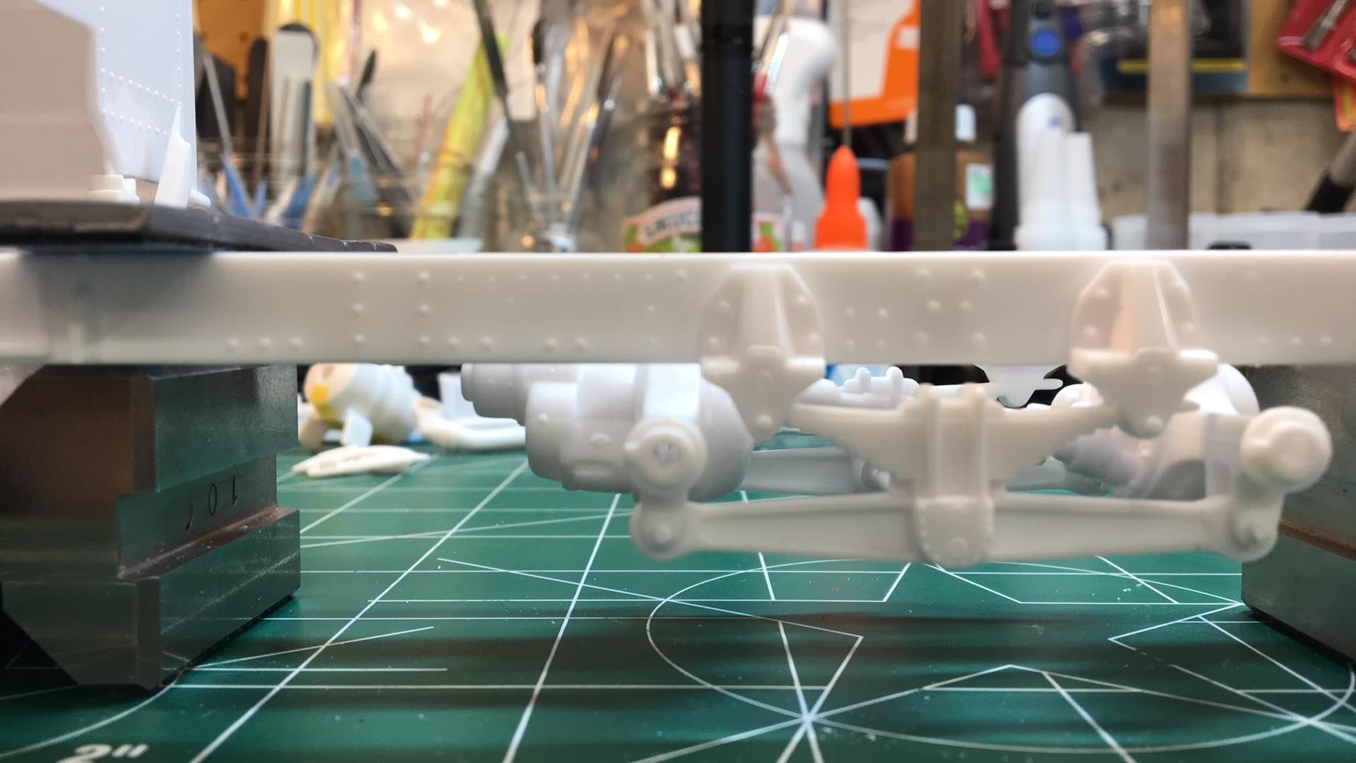
This weekend I finally got the rear suspension and axles "tacked" in. The molding of the Hendrickson beams and the axles is not great -- loads of "slop" all over the place with these. To try to tighten things up, I had a buddy help me and we drilled the beams and then installed pins through the axle brackets and beams (like the real 1:1 suspension had). Still some "tweaks" to do, but it's progress. It also looks like the front torque rod is a bit long. The forward axle is too "flat" and that makes the inner drive shaft between the axles not long enough. So some correction to do there too I think.
-
AMT "Miller" GMC Astro 95
Goodwrench3 replied to Goodwrench3's topic in WIP: Model Trucks: Big Rigs and Heavy Equipment
A little more work this weekend. Got the front hinges cut down.