

Goodwrench3
-
Posts
795 -
Joined
-
Last visited
Content Type
Profiles
Forums
Events
Gallery
Posts posted by Goodwrench3
-
-
This weekend I was able to finally "tack" the hinges in place and make sure the cab tilted with the bumper on and did not have any binding/clearance issues after lowering the cab. Big win ! I will probably need to move the bumper up a bit when it's finally assembled.
I also got the front torque rod adjusted so the rear axles are better oriented and the center drive shaft fits right.

-
 1
1
-
-
Just now, Rockford said:
Yes, it's mainly the front pinion angling down that hurts the trained eye, like looking at a left hand thread, just not comfortable with it.
Agreed. It didn't "smell right" to me.
I've been trying to find a 1:1 photo of an Astro 95 with a Hendrickson suspension to try to see angle of the axles and the torque rods, but I haven't been able to find any yet.
-
5 hours ago, Rockford said:
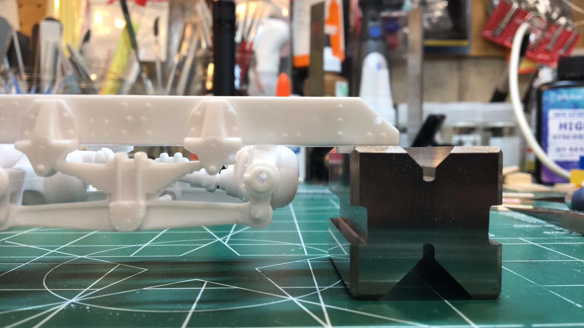
You're right about the torque arms, you can see the rear axles are splayed outwards at the top so that the pinion angle is pointing downwards. Not right.
I think the rear torque arm is probably OK ? I would expect the rear axle to be "canted" back a bit like it is to make the drive line between the front and rear axle more of a straight line.
-
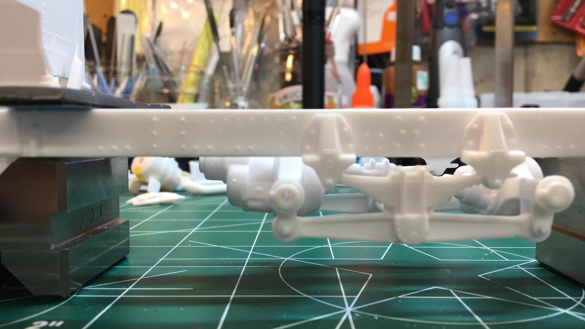
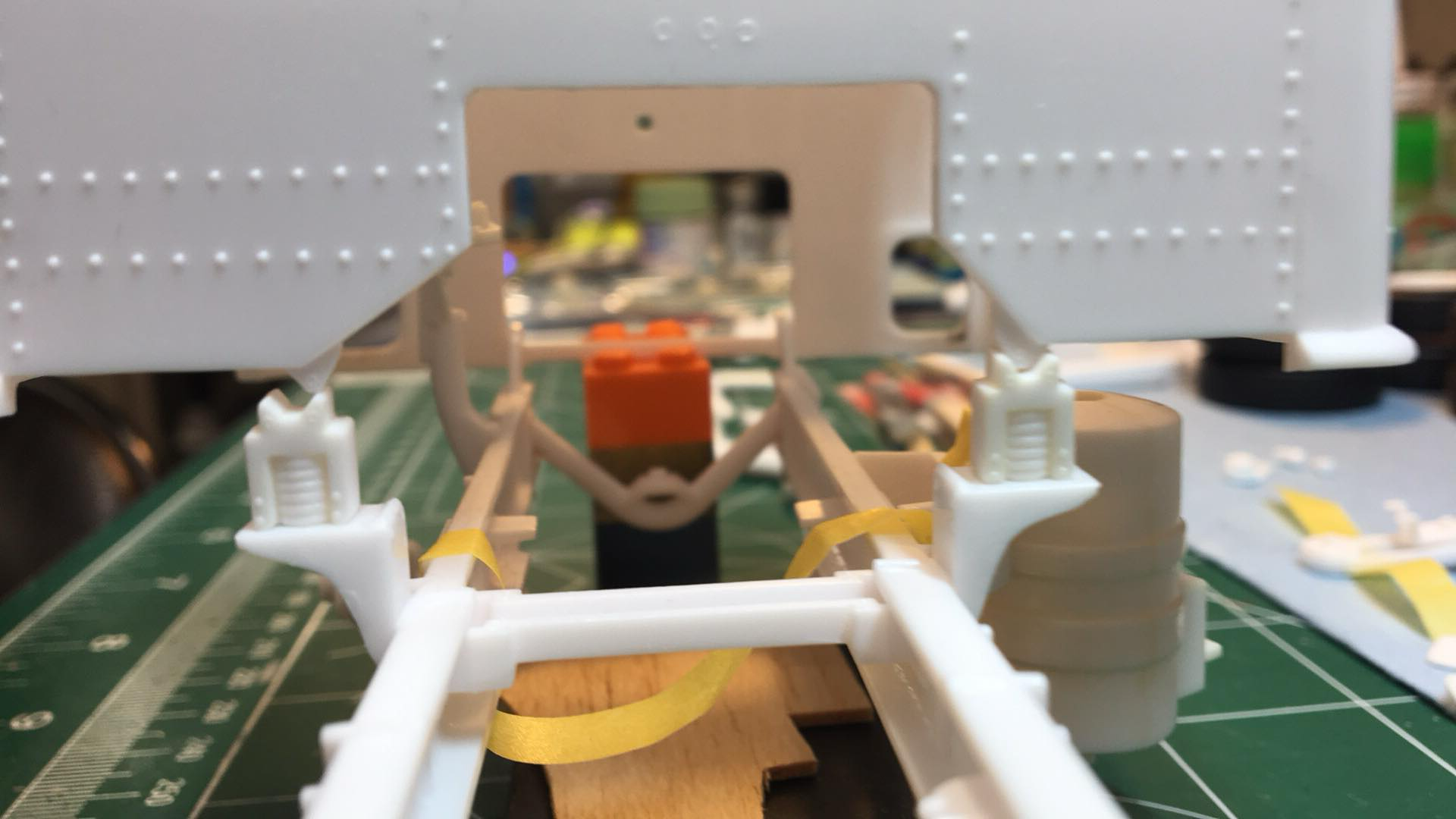
This weekend I finally got the rear suspension and axles "tacked" in. The molding of the Hendrickson beams and the axles is not great -- loads of "slop" all over the place with these. To try to tighten things up, I had a buddy help me and we drilled the beams and then installed pins through the axle brackets and beams (like the real 1:1 suspension had). Still some "tweaks" to do, but it's progress.
It also looks like the front torque rod is a bit long. The forward axle is too "flat" and that makes the inner drive shaft between the axles not long enough. So some correction to do there too I think.
-
4
-
-
A little more work this weekend. Got the front hinges cut down.
-
1
-
-
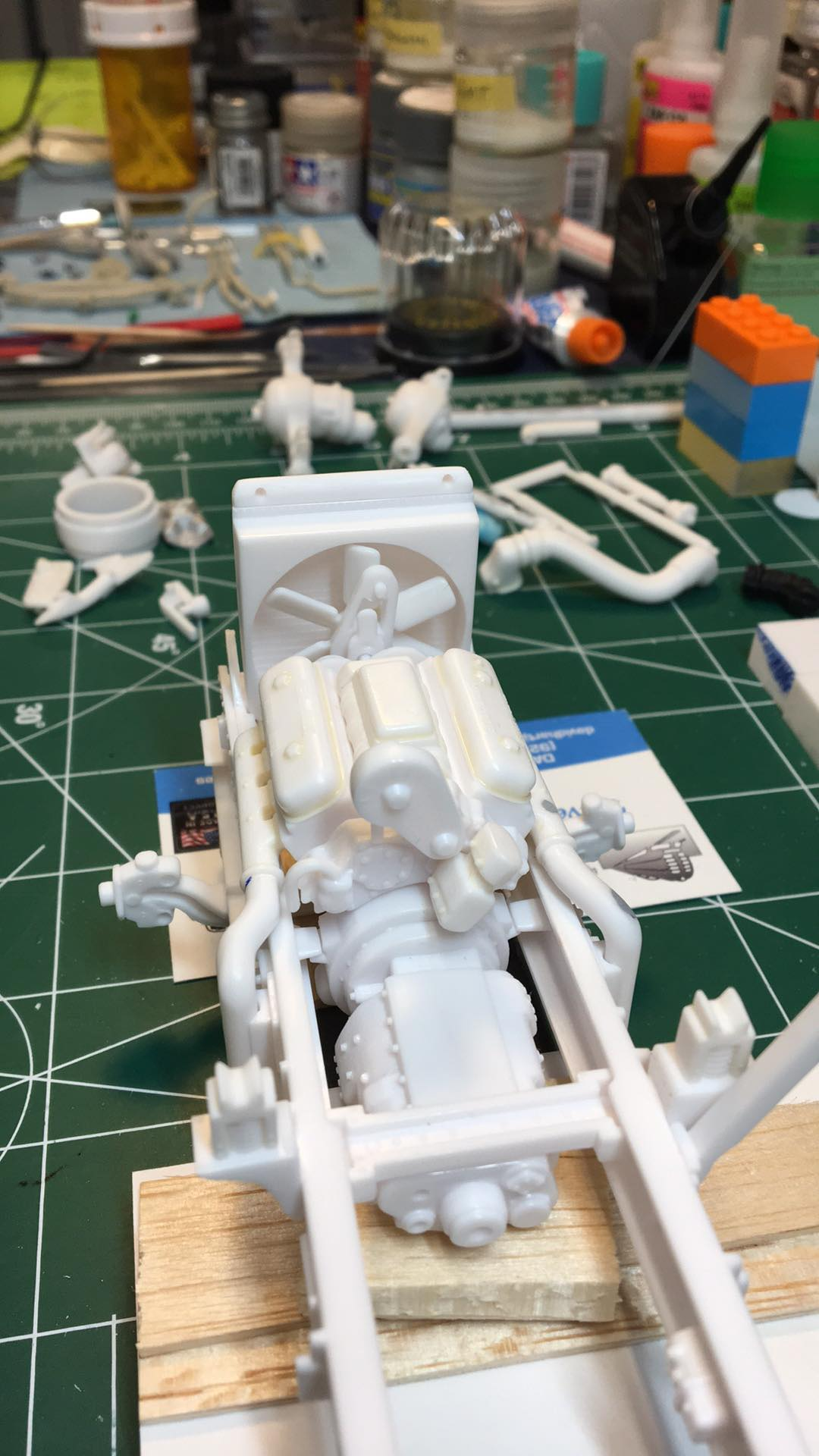
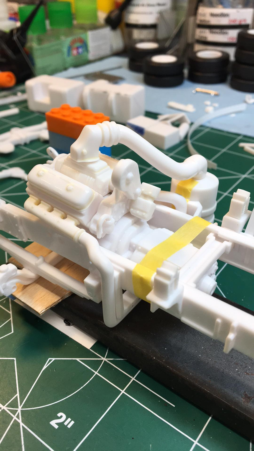
Worked a bit more on the fit of the crossover pipe today and test fit radiator with engine in. Finally attached the fan support bracket to the block! Was sweating that one as it needed to land the fan in the center of the fan shroud.
-
4
-
-
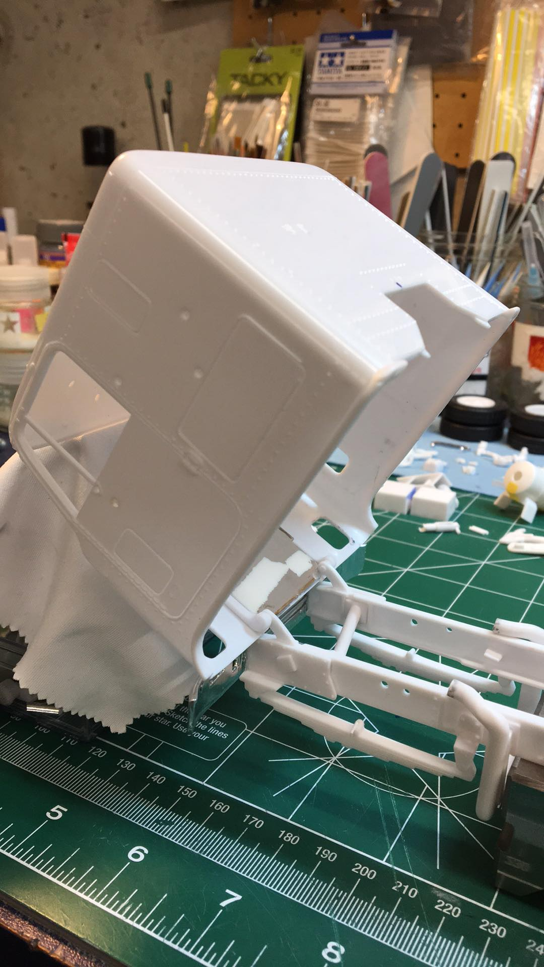
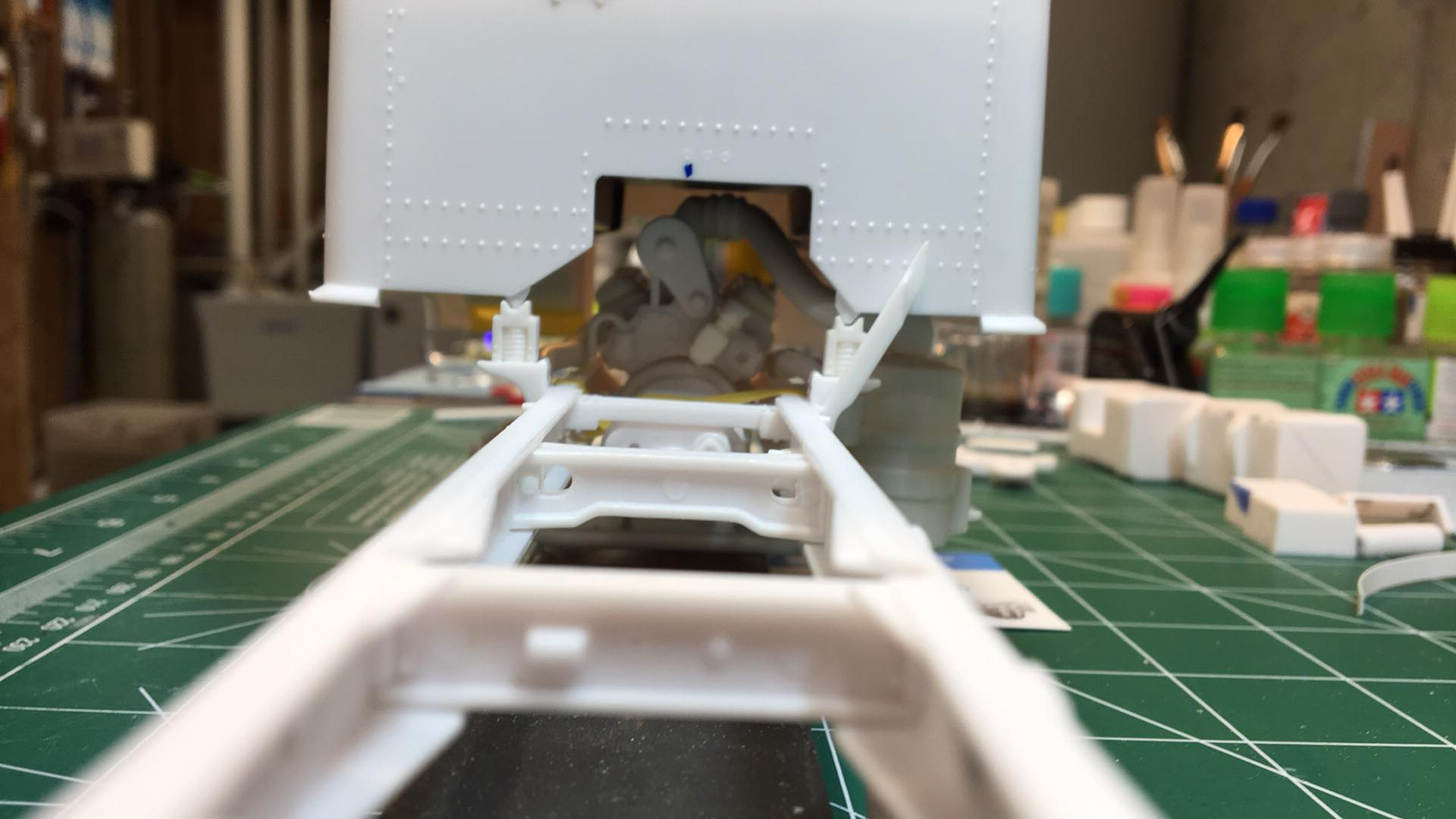
After the cab was lowered, I wanted to check to see that there were no clearance issues with the interior tub in.
OK -- it clears. Just ! Man that's close !
-
4
-
-
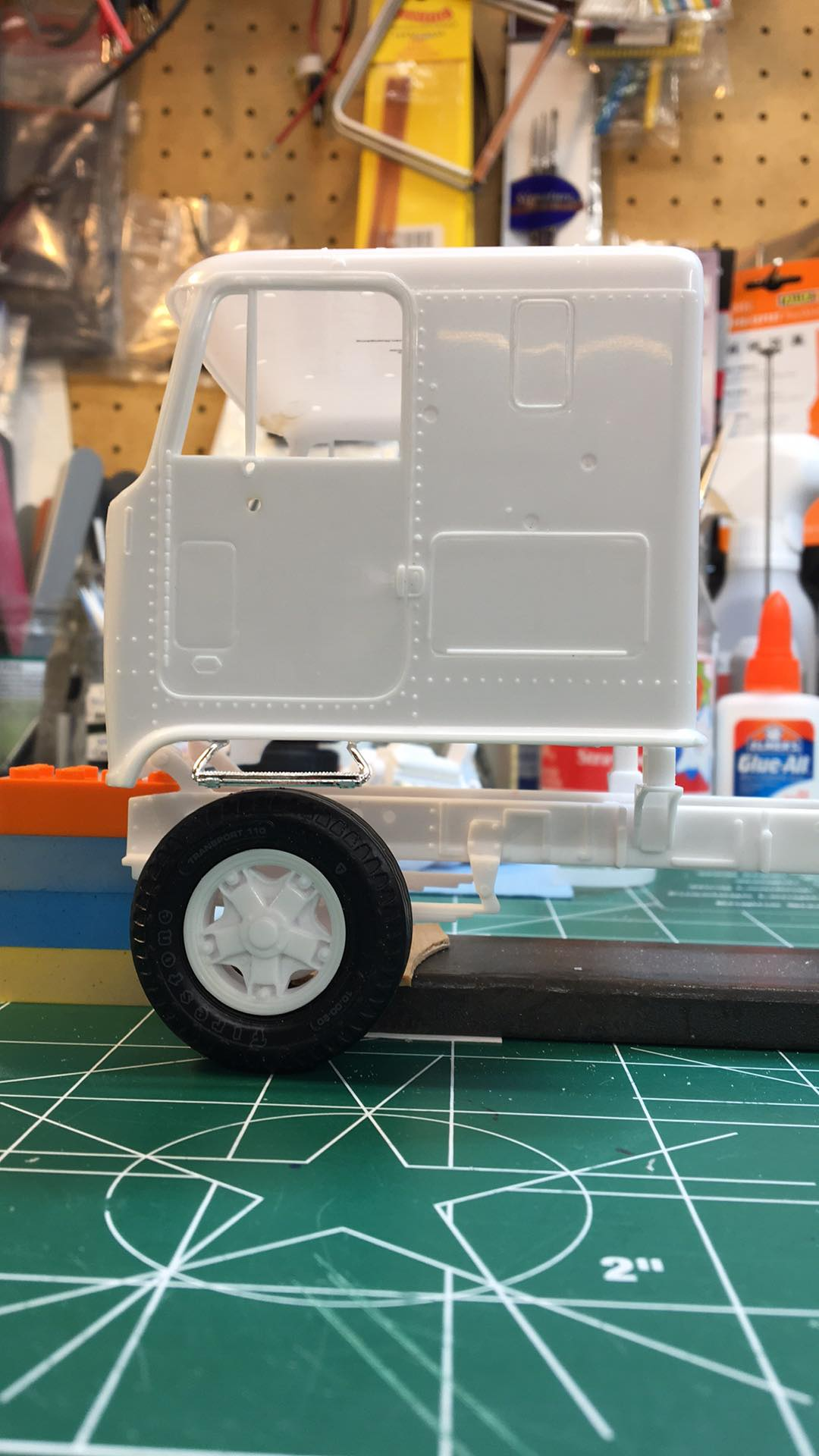
I got the cab supports lowered. Here are before and after photos. It seems about right now based on 1:1 photos.
-
3
-
-
Slowly getting all the frame stuff on the right side mocked up before I start lowering the cab -- to make sure there aren't clearance issues with anything.
-
2
-
-
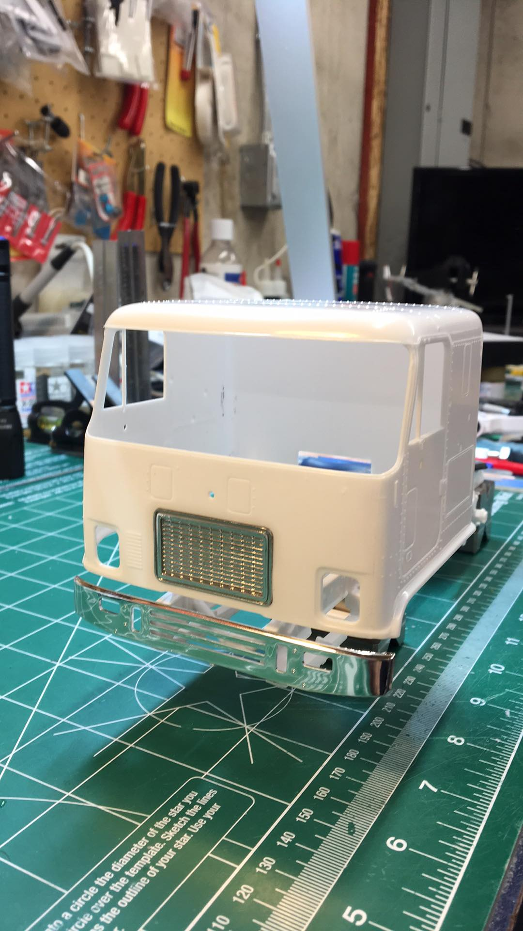
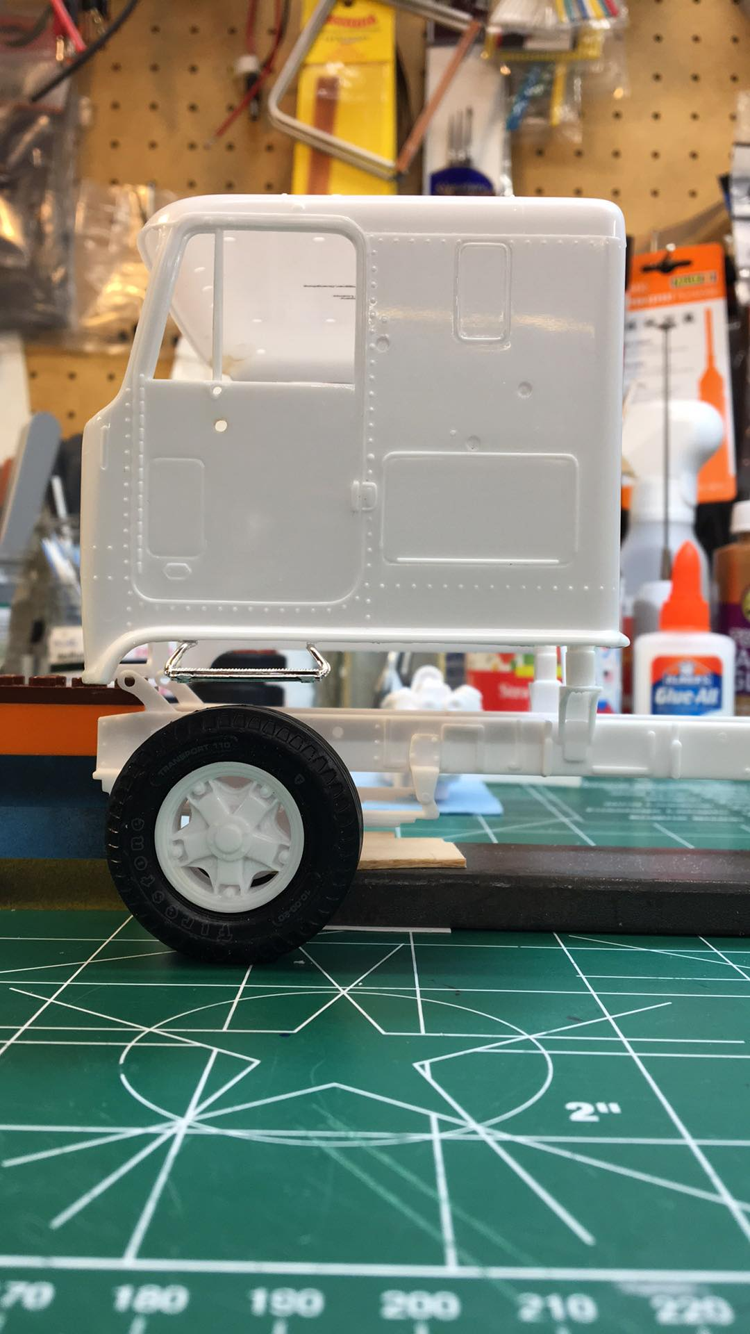
Well now the next chore. Of course, the cab sits waaaaaaaaaaay too high on this kit. Looks like it needs to be lowered about 1/8" or 3/16" to sit correctly. Based on 1:1 photos, the bottom of that cab step should be about level with the top of the front tire.
-
3
-
-
Testors ELO (Easy Lift Off) has worked on everything I've tried it on -- Krylon, Rustoleum, Tamiya, etc.
Another really good model paint stripper is this one: https://www.facebook.com/p/Daves-Magic-Paint-Stripper-100066390534848/
-
Thanks !
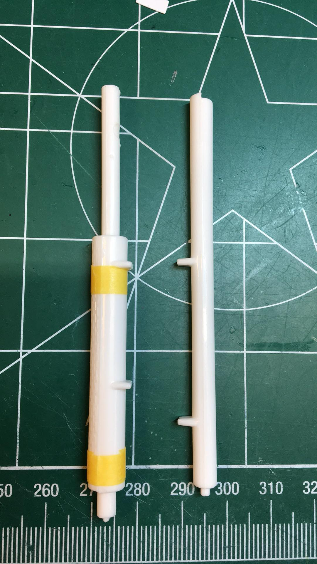
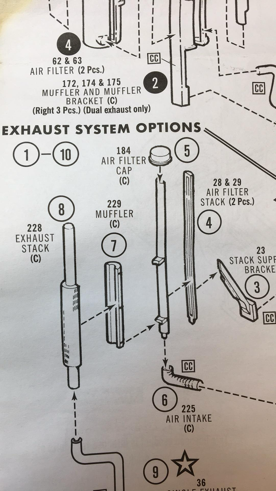
My next quandry -- for the single exhaust, I'm guessing the tabs on the exhaust need to be removed ?? And just attach the exhaust to the air intake pipe using the tabs on it ? The instructions don't show the tabs on the exhaust (parts 228 and 229).
-
10 hours ago, Rockford said:
I usually envy you 1/25 guys but on this one I'll keep my snappers.
I'm sure you'll make a great job of it. It does build into a great looking truck.
I'd be interested in your thoughts/comments. Send a private message if you think that would be more appropriate.
Thanks!
-
Houston, I think we need an adjustment. Looks like I need to fiddle with the rear cab supports now.
-
1
-
-
Well, a year later and this kit is back on the bench again -- originally parked in frustration with the rear suspension.
Working from the other end now. Hopefully tomorrow I can drop the cab on to see how it looks. I know the cab on these Astros look like they sit way too high, so I want to see before I get too far.

-
Next task is going to be surgery on the "Y" exhaust to convert it to single exhaust. Not looking forward to that. Haven't done something like that before -- so getting it to look like I didn't cut it etc. will be a bit of a challenge.
-
1
-
-
A bit of the interior work done too.
-
1
-
-
Moving along slowly. Took a break to work on something else for a while. Test fitting the drive wheels and tires from Moluminum with the kit steers.
-
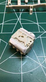
Another area that needs work -- the front crossmember. This one shouldn't be an open "U" (and of course shouldn't have a pin sticking up to go through the oil pan). The triangle cut outs are there because of another issue -- to clear the fuel filter on the left side. But--the crossmember is actually not located correctly because the fuel filter should not be directly on top of the crossmember. So -- filling this crossmember and removed the pin. We'll deal with the fuel filter later.
-
1
-
-
The valve covers on the FE 360 engine in the kit were a disappointment. Luckily the valve covers from an AMT kit FE engine fit well and match the ones I've seen on every '72 F-250 360 engine (with the "Power by Ford" on them).
-
2
-
-
There are several things that are "off" with this kit -- it's unfortunate. But I like the truck.
I'll keep posting "issues" for those that want to build a closer, more accurate replica of the 1:1 '72 F-250 4X4. If you just want to build the kit out of the box and don't care, you can disregard these items.
Thanks for your interest !
-
Let me re-state... If only they would re-pop an elliptical tanker kit. 😉 AND come out with an elliptical tank kit in 1/25 scale 🙂
-
I've started this as a club build and thought it might be a good idea to document all of the issues/corrections/fixes etc. that I've run into.
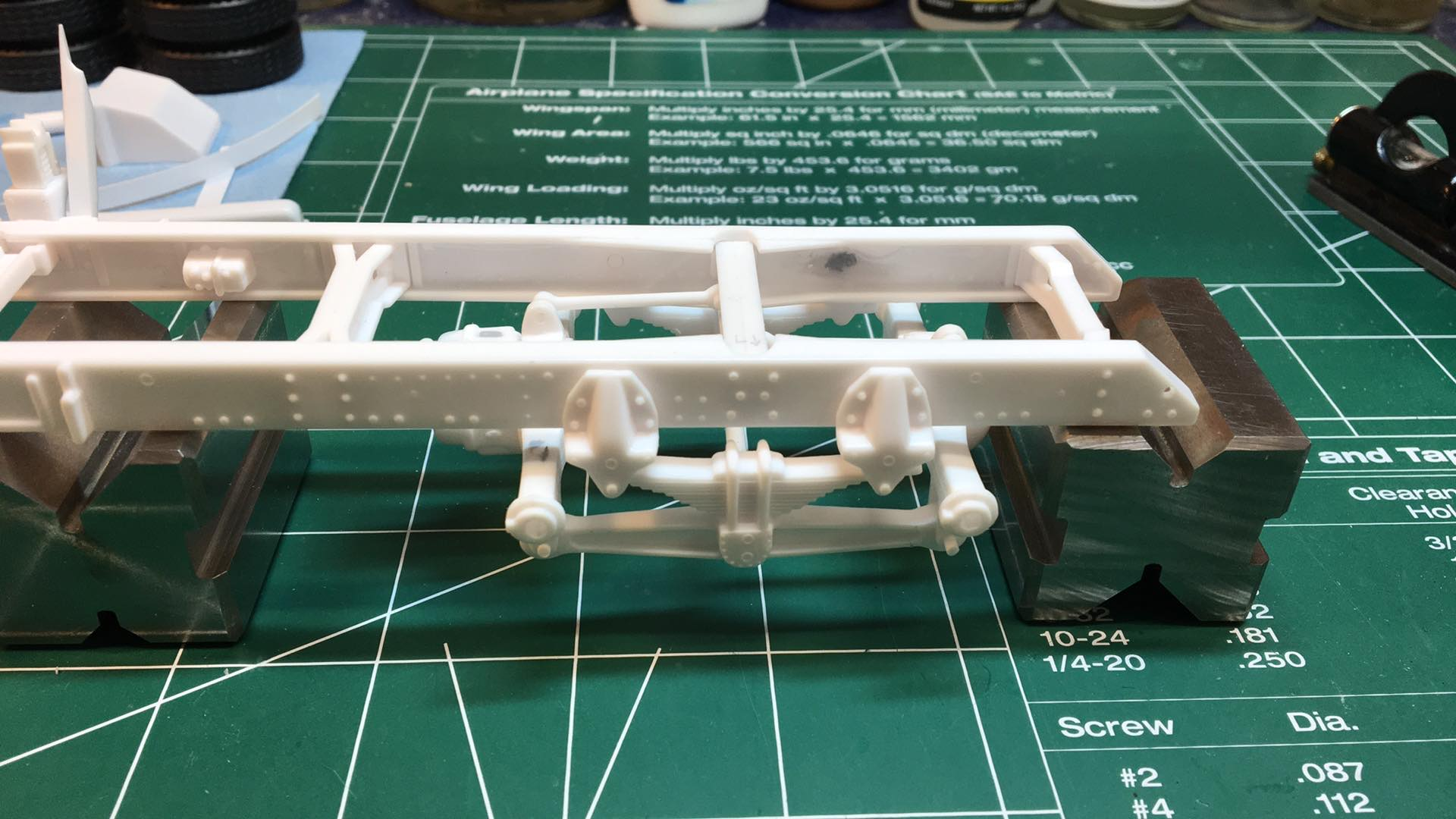
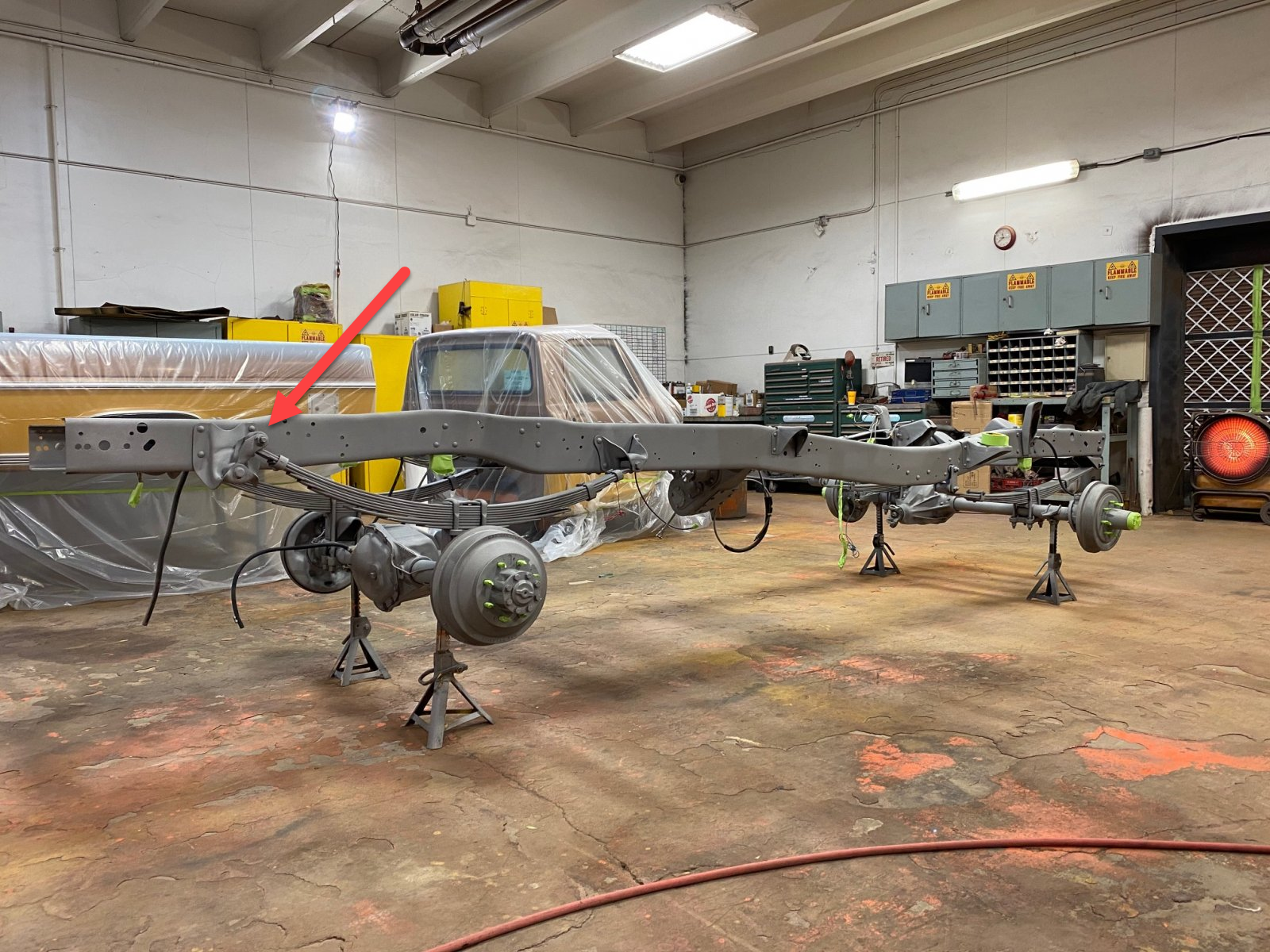
First issue is the rear springs. The top of the rear of the spring extends above the mount and this interferes with the box sitting properly on the frame. It needs to be filed down level with the mounting plate. In the image, the spring on the left is the standard kit rear spring. The spring on the right has been filed down as described. Note also in the 1:1 photo how the spring should have been molded -- note how the top of the spring at the rear is below the top of the mounting plate.
More to come...
-
6
-
 1
1
-
-
If only they would make an elliptical tanker 😞
-
1
-


.jpg.c2d43789e63e6e79196c690c7c4bd86d.jpg)


AMT "Miller" GMC Astro 95
in WIP: Model Trucks: Big Rigs and Heavy Equipment
Posted
Hi -- what are these ? " 1-2-3 blocks and a set a precision parallels. " ??
Can you send me a link for these ?
Thanks !