

ShakyCraftsman
-
Posts
351 -
Joined
-
Last visited
Content Type
Profiles
Forums
Events
Gallery
Posts posted by ShakyCraftsman
-
-
Thanks everyone
Ron G
-
25 minutes ago, Mopar - D said:
Amazing Ron! Your project is definitely taking shape now. When are you going to start spraying some paint on? Do you have your 5’ of shelf space ready?
Soon, no I still have to make that.
Ron G
-
Hey guys
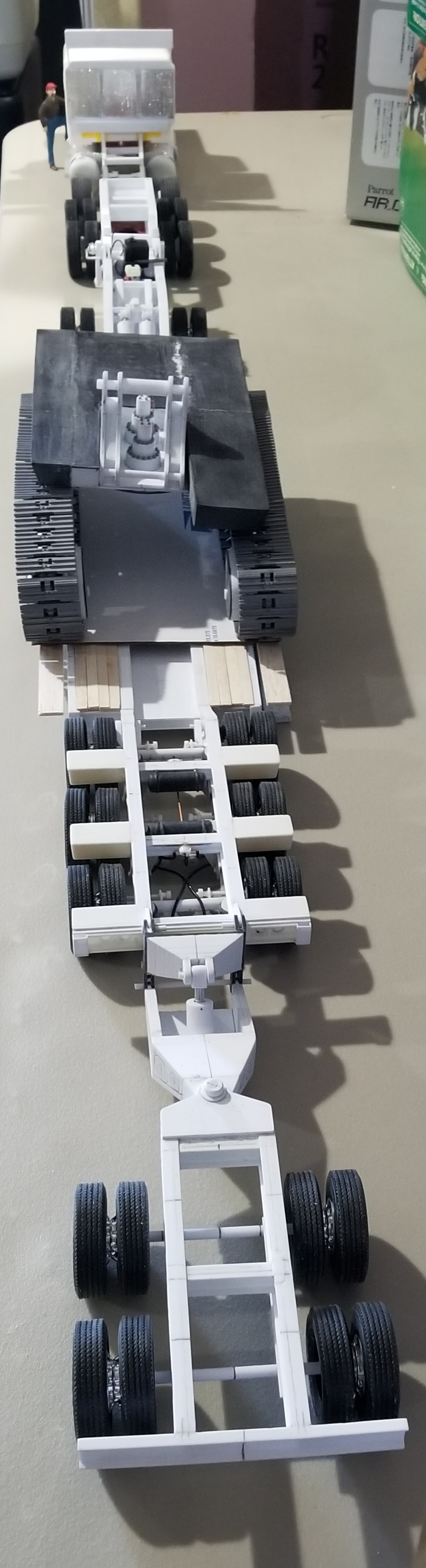
I have the booster/stinger almost completely built, I'd say about 80%. I assembled everything temporarily together to see how it looks, and WOW!!!! It's Lloooonngg!!!
 So here are some pictures for you all to perose.
 this view shows the mounting bracket, the attachment/pivot bracket with the hydraulic cylinder and the booster/stinger. I have to add tge power pack, hydraulic lines and nitrogen cylinder/tank.
same thing from above.
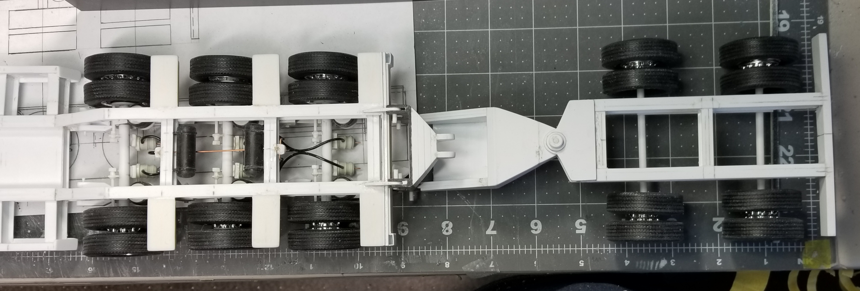
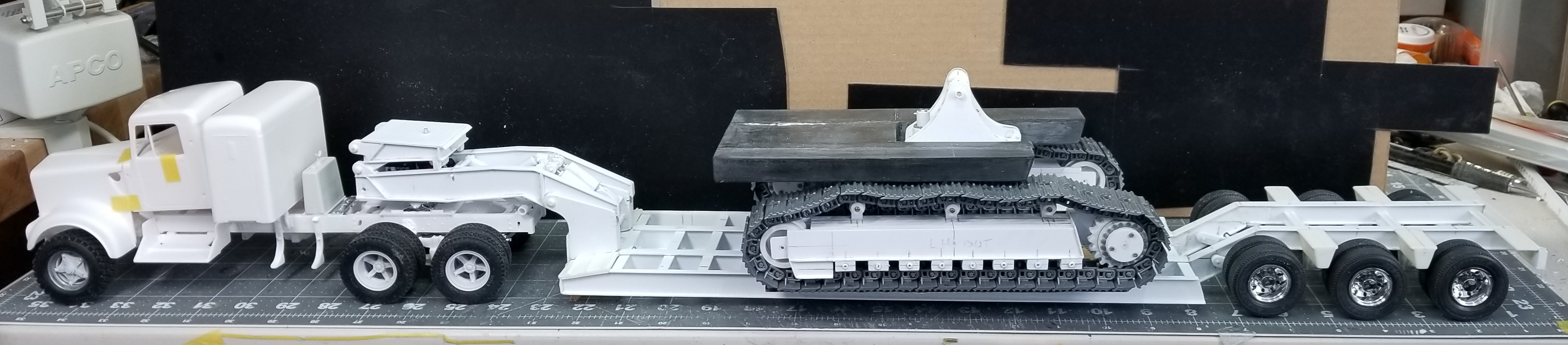
this view shows the whole set up, WOW! It's over 5' long!
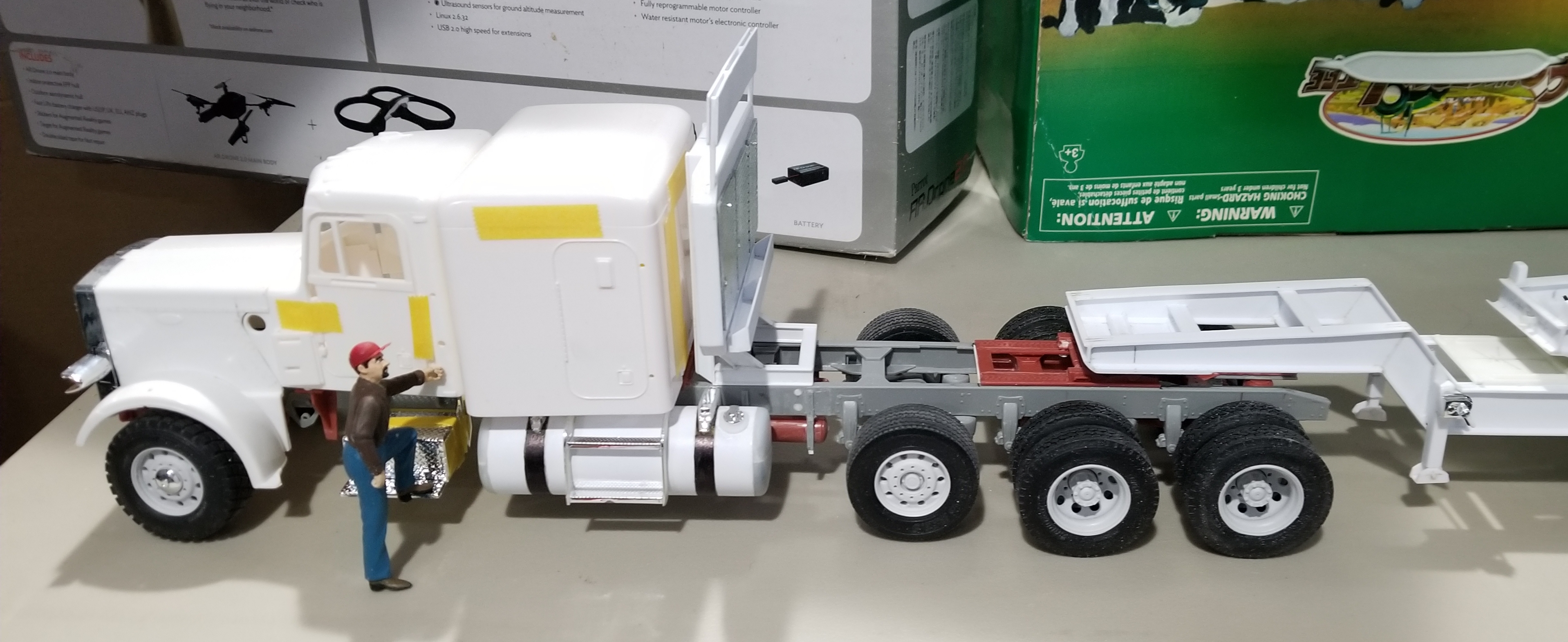
this view shows the Peterbilt 359 heavy haul tractor attached to the jeep
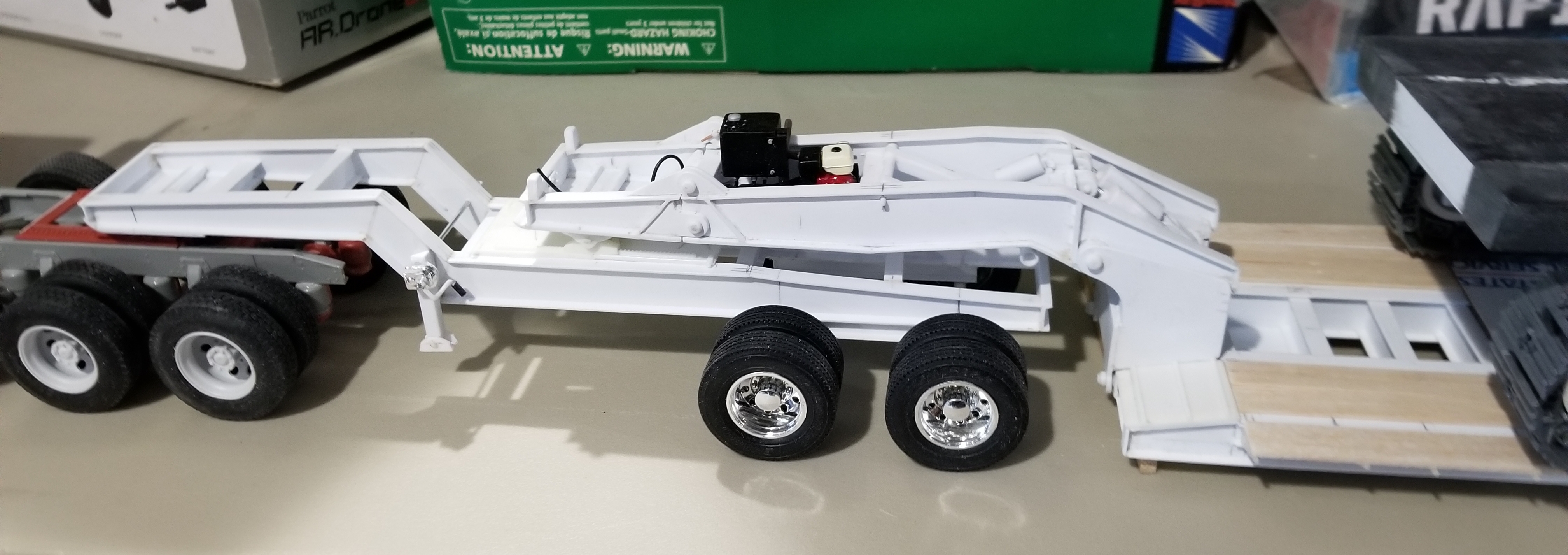
this view shows the XL 80 JPS jeep attached to the trailer.
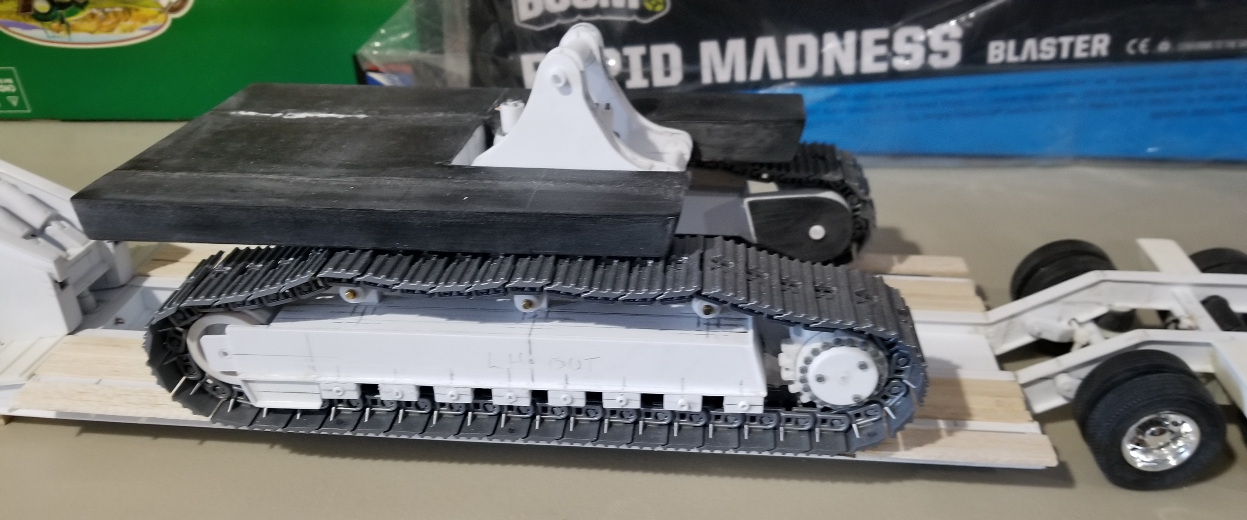
this view shows the XL 130 HD drop nose RGN trailer with the Cat 374F L sitting on it. The outrigger boards and deck boards are in place.
this view shows the rear of the trailer attached to the booster/stinger.
this view shows the XL 42 PMB booster/stinger.
this view shows the mounting bracket, the attachment/pivot bracket with the hydraulic cylinder and the booster/stinger. I have to add tge power pack, hydraulic lines and nitrogen cylinder/tank.
same thing from above.
this view shows the whole set up, WOW! It's over 5' long!
this view shows the Peterbilt 359 heavy haul tractor attached to the jeep
this view shows the XL 80 JPS jeep attached to the trailer.
this view shows the XL 130 HD drop nose RGN trailer with the Cat 374F L sitting on it. The outrigger boards and deck boards are in place.
this view shows the rear of the trailer attached to the booster/stinger.
this view shows the XL 42 PMB booster/stinger.
This view shows the whole thing from the rear looking forward. You can just see the driver waayy up there at the front...lol

 well that's it for now be back with more updates soon.
Ron G
-
Based on my last order, about 3 to 4 weeks
Ron G
-
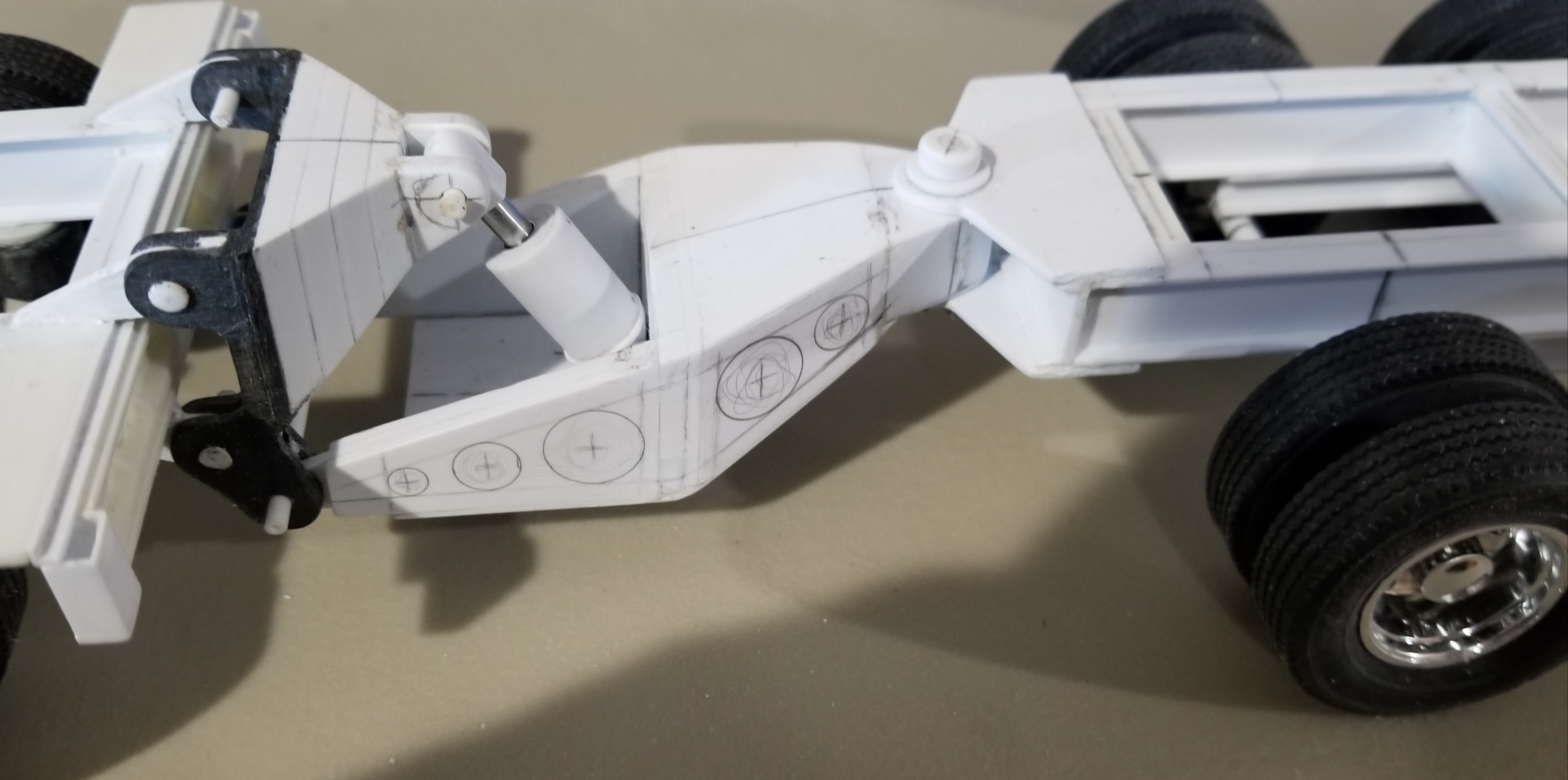
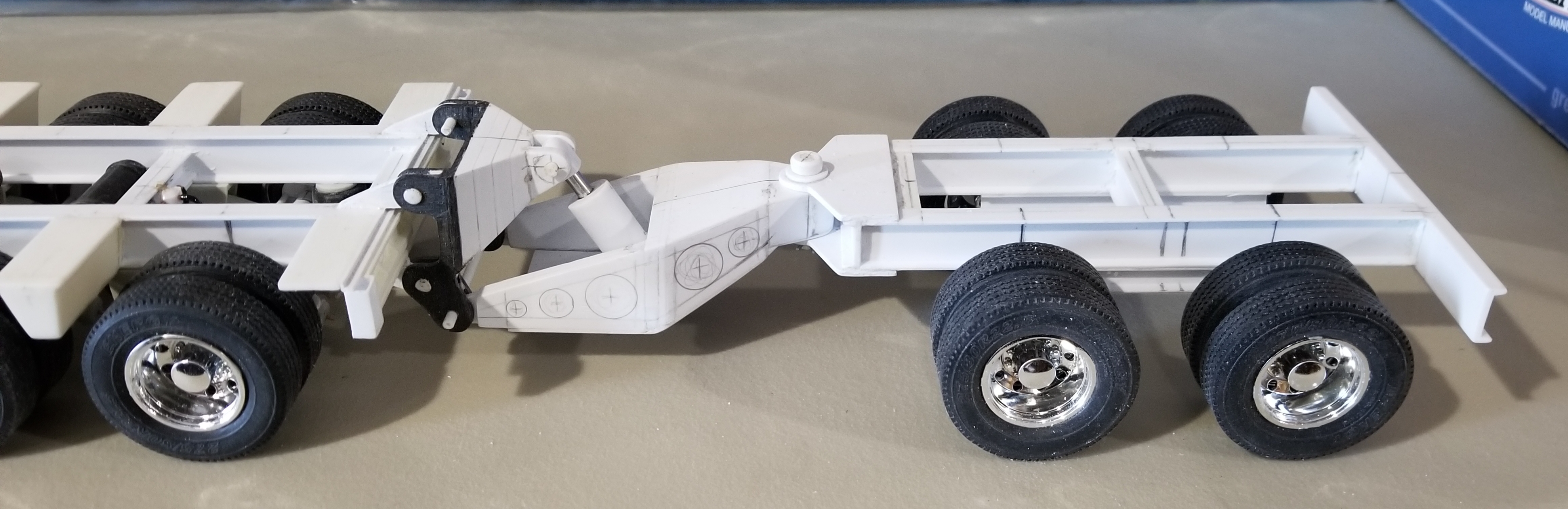
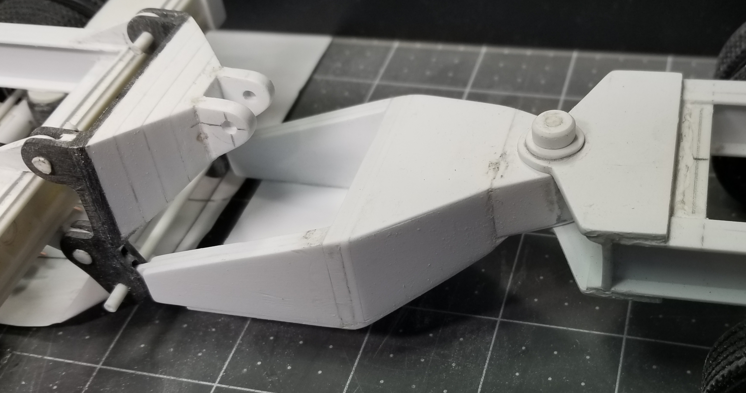
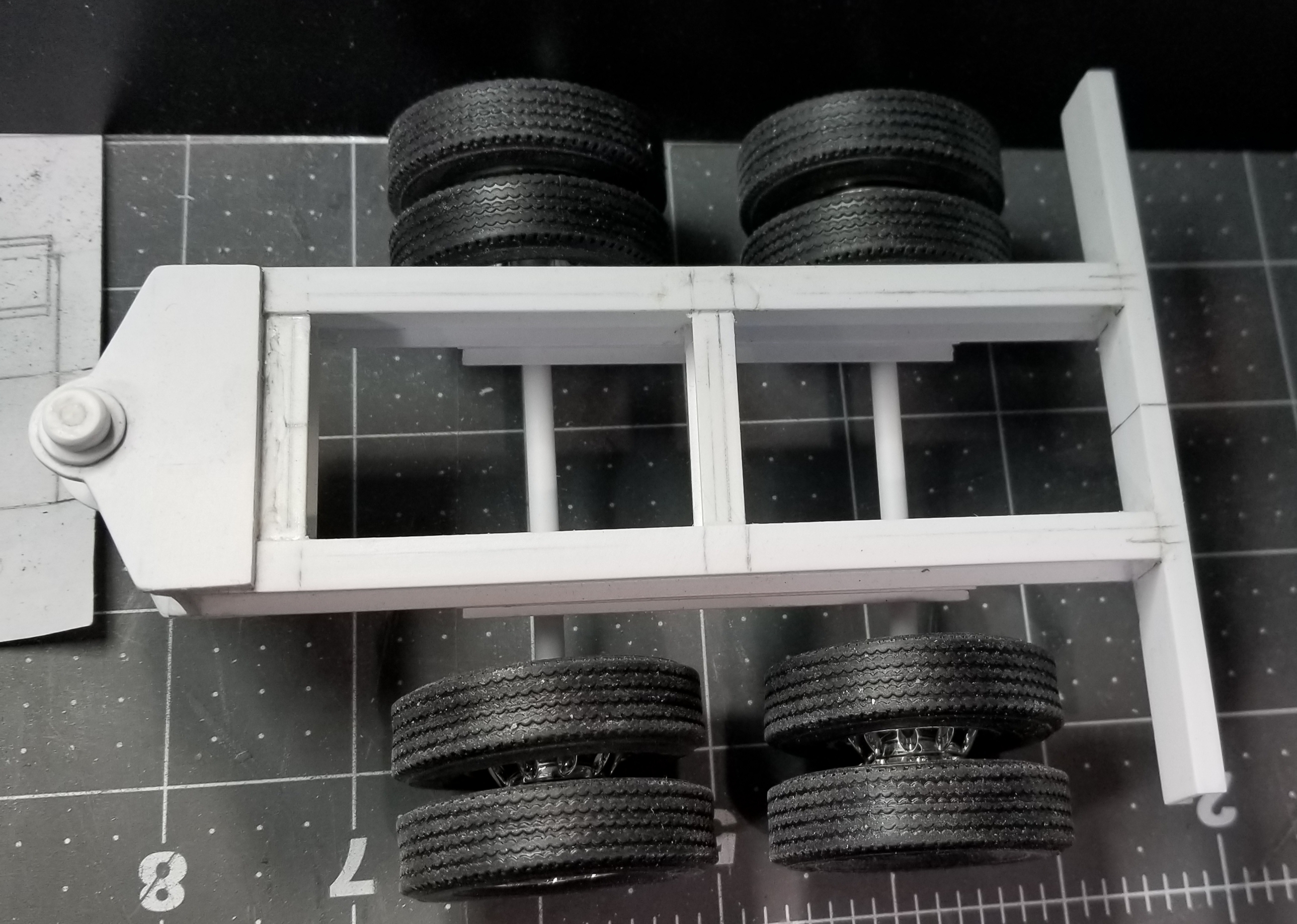
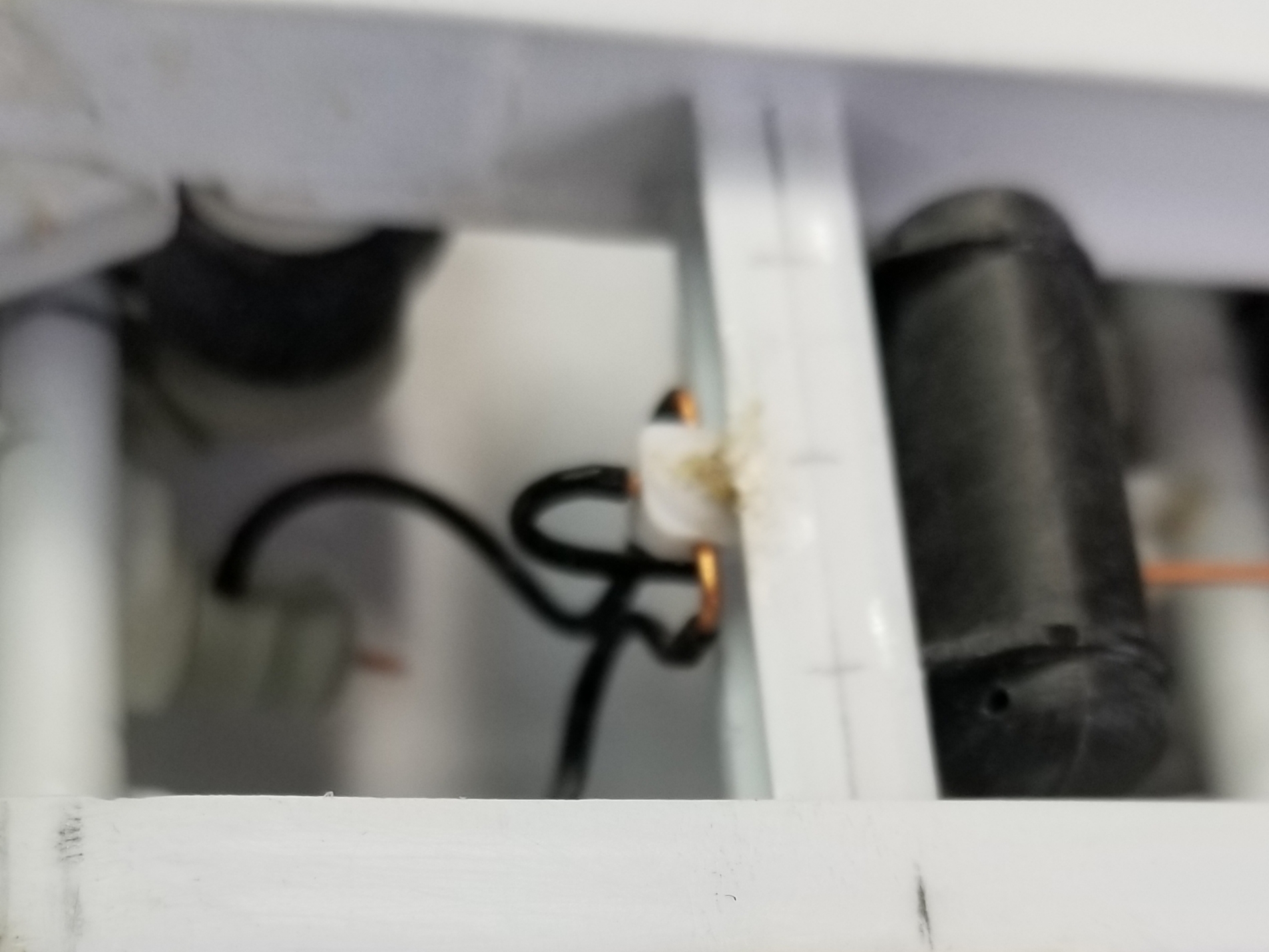
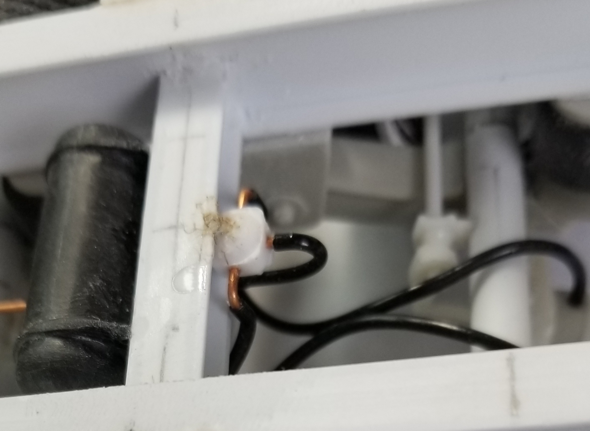
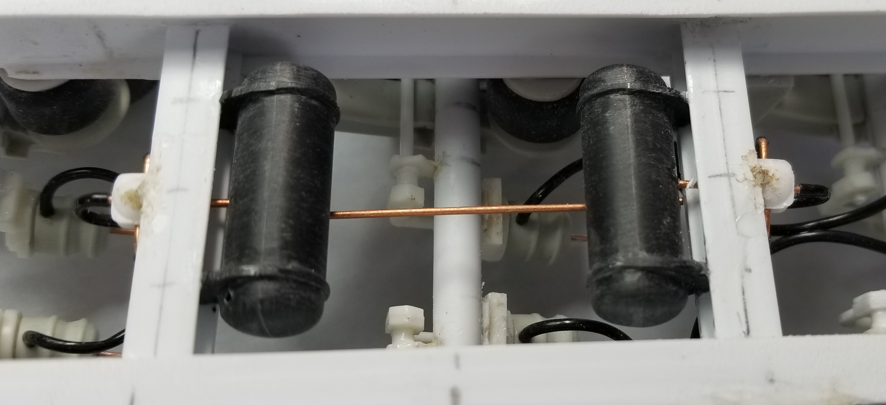
Hey guys
I now have the bracket that goes from the mounting bracket to the booster/stinger pivot point. I still need to create the cylinder, nitrogen chamber and attachment mechanism.
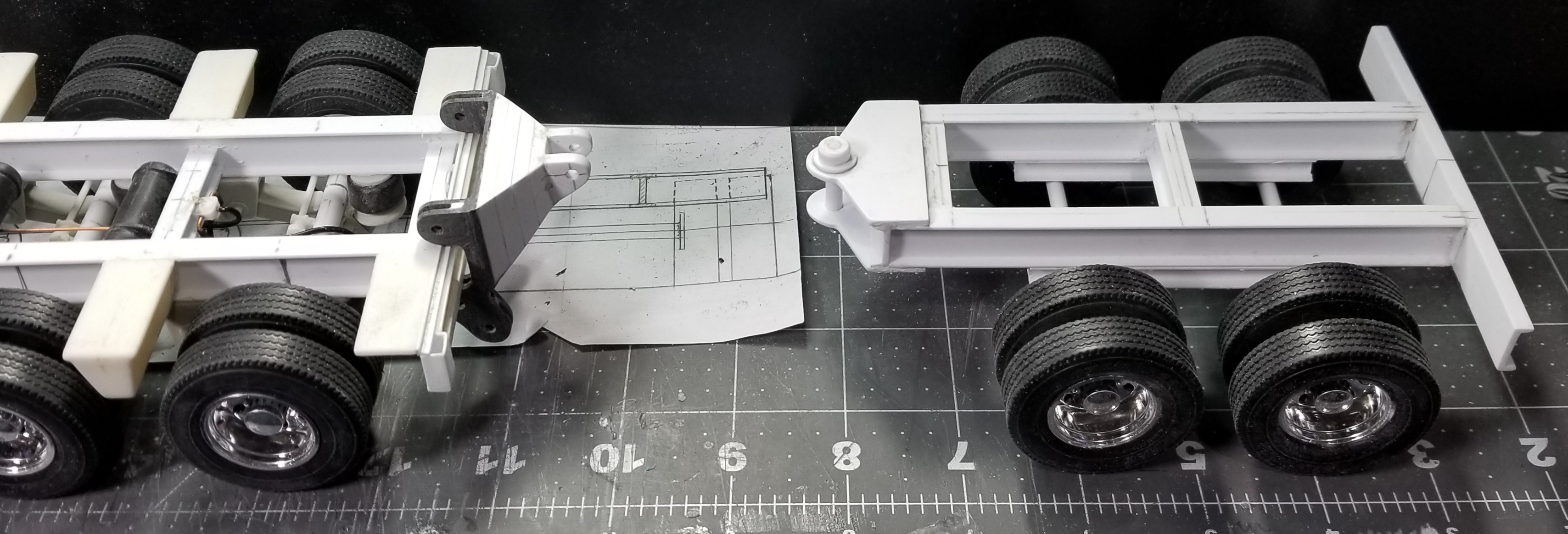
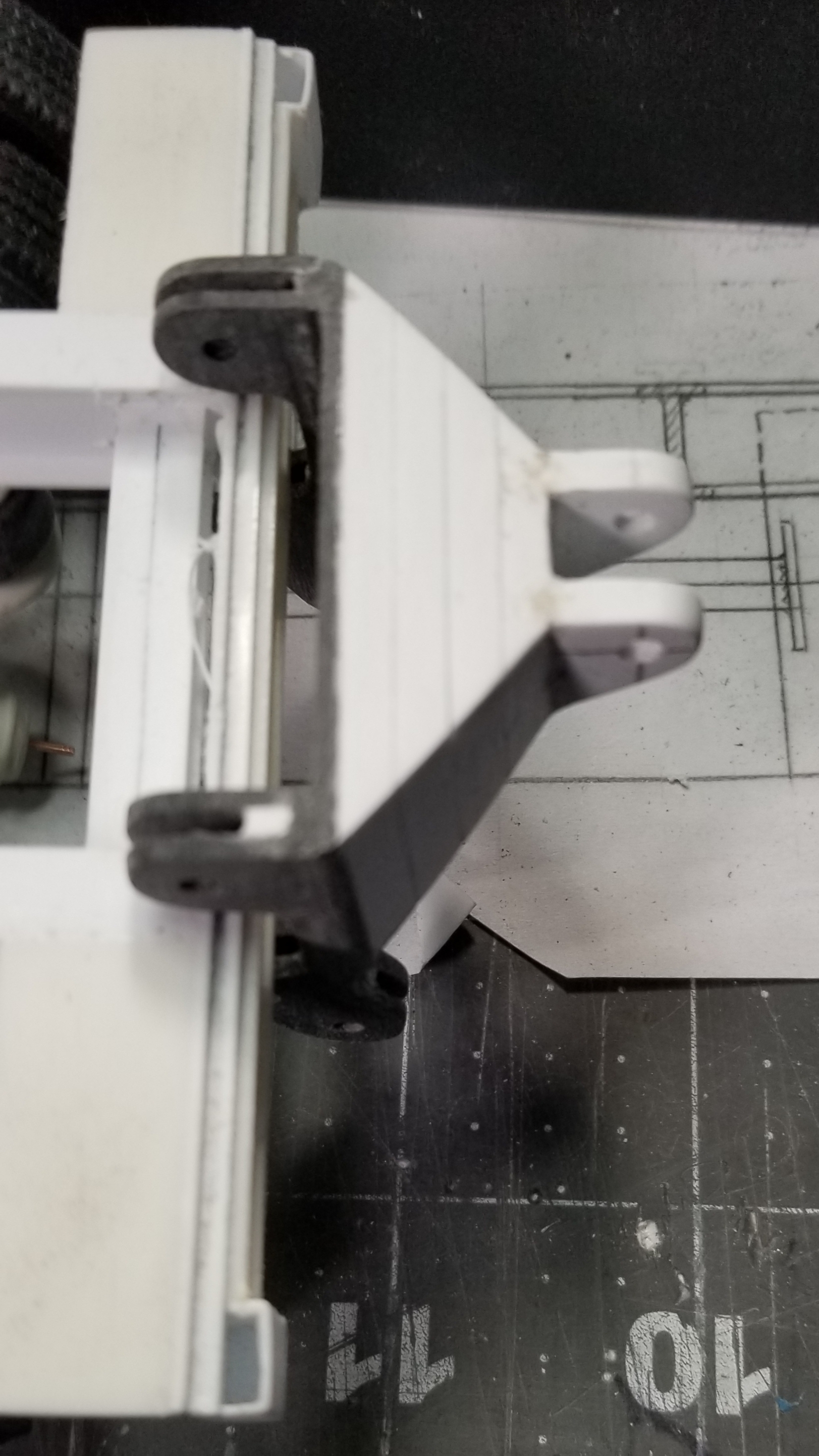
this view shows the rear of the trailer, mounting brackets and the booster/stinger.
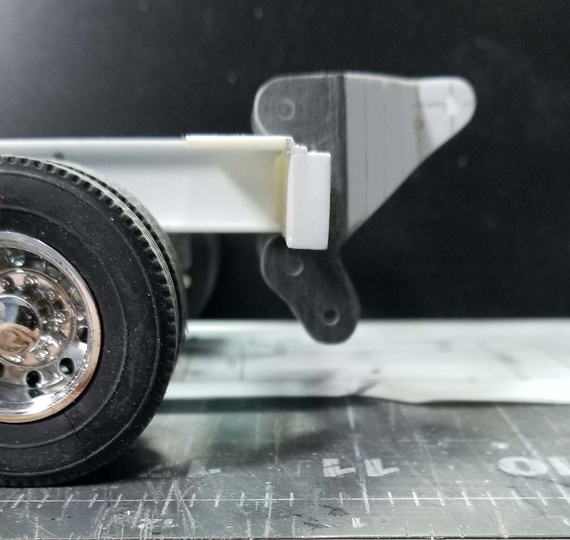
this view shows the mounting bracket and the attachment point for the hydraulic cylinder.
top view of the whole set up. Well that's it for now be back soon.
Ron G
-
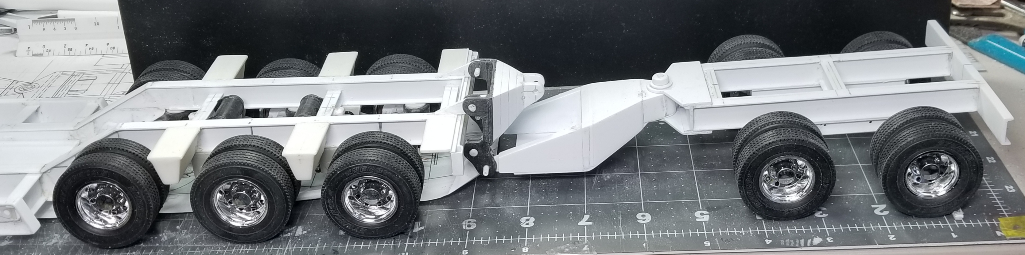
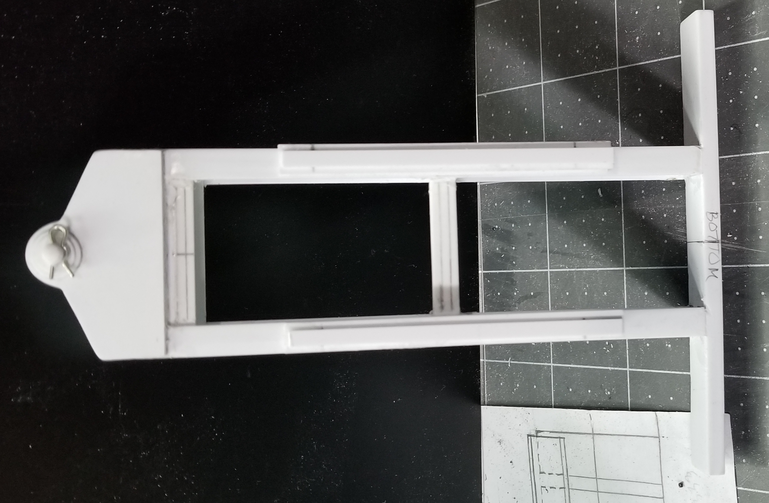
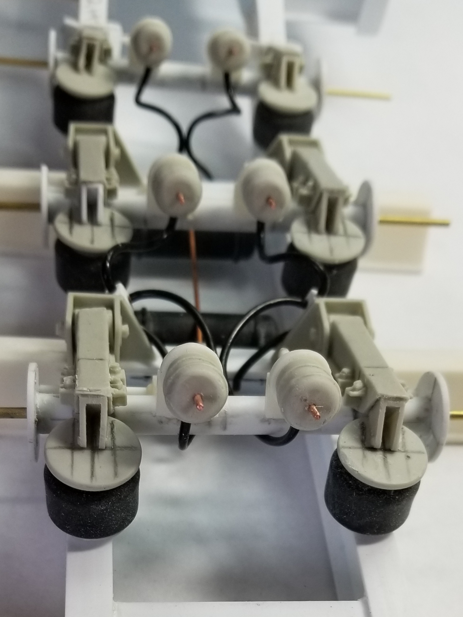
Hey all
I started on the XL 42 PMB booster/stinger. Its a nitrogen charged hydraulic one. This allows you to adjust the ride height and load on the trailer.
this view shows the booster/stinger and the mounting bracket that attaches it to the rear of the trailer. I need to make the bracket that attaches to the lower pivot on the mounting bracket and the upper attachment point for the hydraulic cylinder, also it attaches to the pivot pin on the booster/stinger.
this view shows the mounting bracket. I still need to add the attachment points to the trailer.
this shows the mounting bracket from the top.
this view shows the beginnings of the booster/stinger and the pivot pin at the front.
this view shows the booster/stinger from the bottom and the pivot pins keeper pin. There's a lot of work that still needs to be done. I'm waiting on air suspensions for it from Moluminum. Well that's it for now be back soon with more.
Ron G
-
Hey all
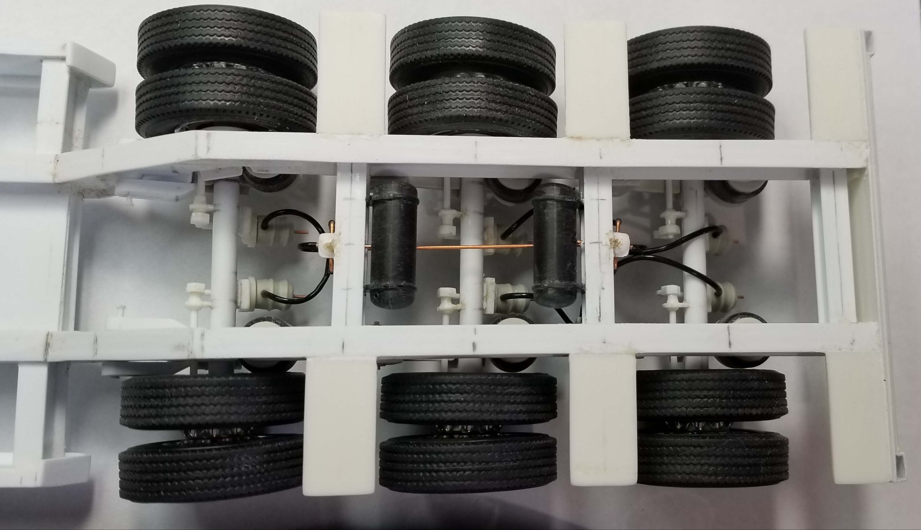
I have the brakes fixed and plumbed. I also took some pictures of the trailer with the deck boards in place.
view from the side.
view of the bottom. You can see the "tee" fittings that I added to the rear axle pivot brackets in order to connect the center brakes and the rear brakes to the air control valve.
view from the rear. This view shows how I added the Moluminum brake chambers to the ones I had on the axles already.
front air control valve.
rear air control valve.
both air tanks and connection pipe. I still need to add the supply and control lines.
View from the top with the tires added.
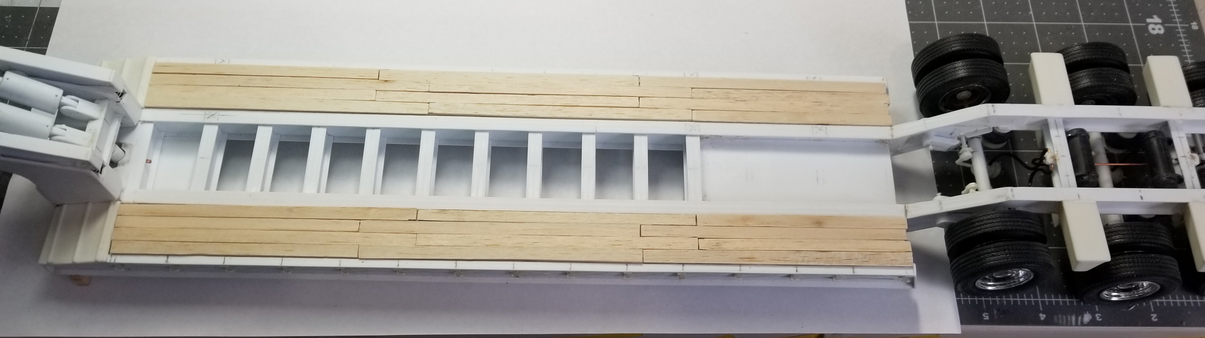
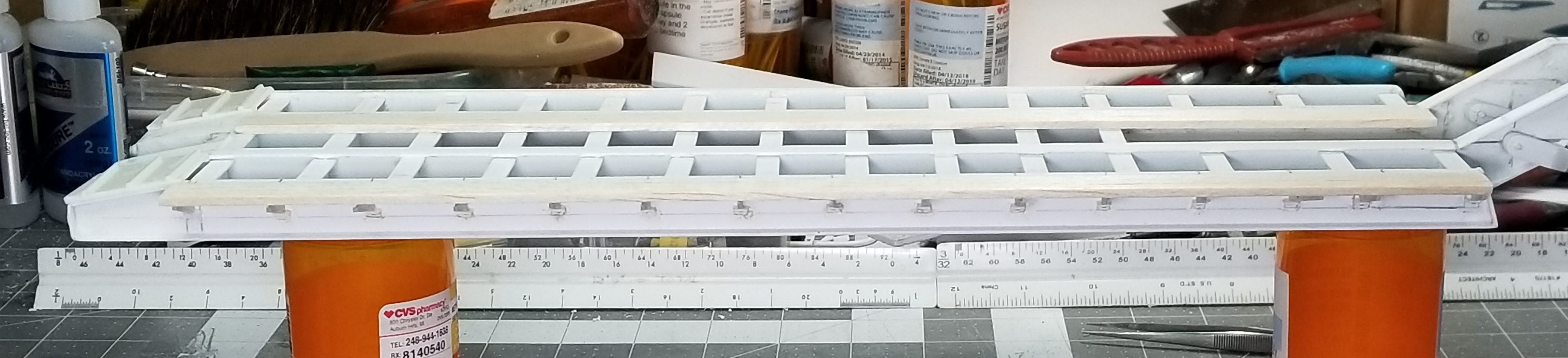
this view shows the deck boards in place.
this view shows the deck boards and the outrigger boards added. Well that's it for now be back with more updates soon.
Ron G
-
Hey all
Today was a lot of small tedious work. I mounted one side of the outriggers to the trailer frame. Cut the two long outrigger boards and I have all the deck boards cut and sized, but didn't get any pictures of those.
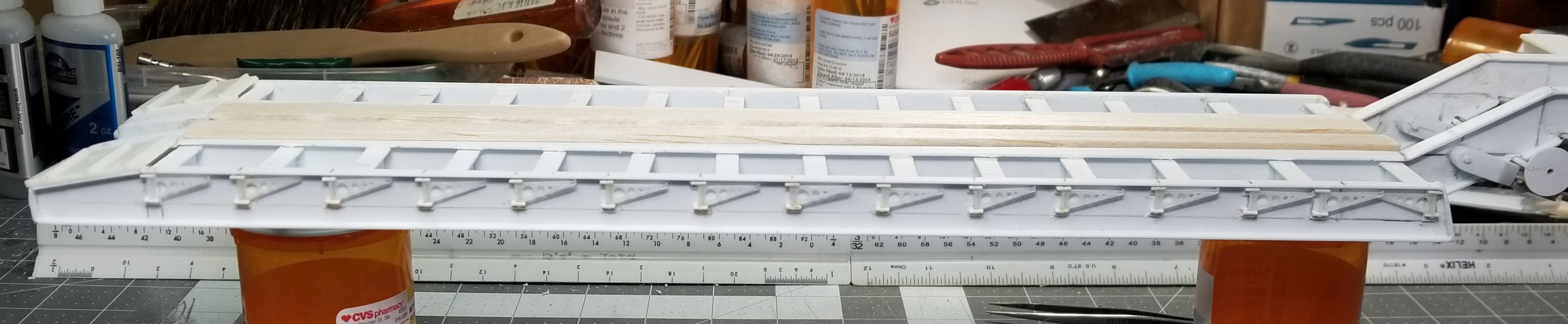
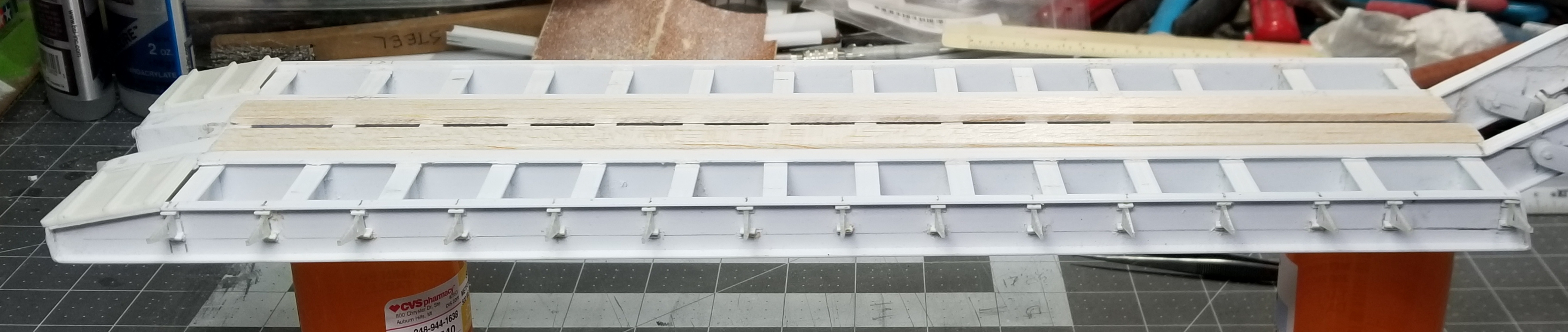
this view shows the outriggers folded in.
his view shows them folded out.
this view shows the outrigger board in place. I wish the outriggers were printed in the white detail plastic, because in the fine detail resin/plastic they are VERY!!!! brittle, and the whole weight of the excavator will be sitting on them. well that's it for now be back with more soon.
Ron G
-
2 hours ago, Mopar - D said:
Ron you sure have a lot of awesome builds going on all at the same time.
Yeah, but it keeps me from getting burnt out on one project....now I can get burnt out on 5 projects...lol🤪🤯😉
Ron G
-
Thanks Mopar
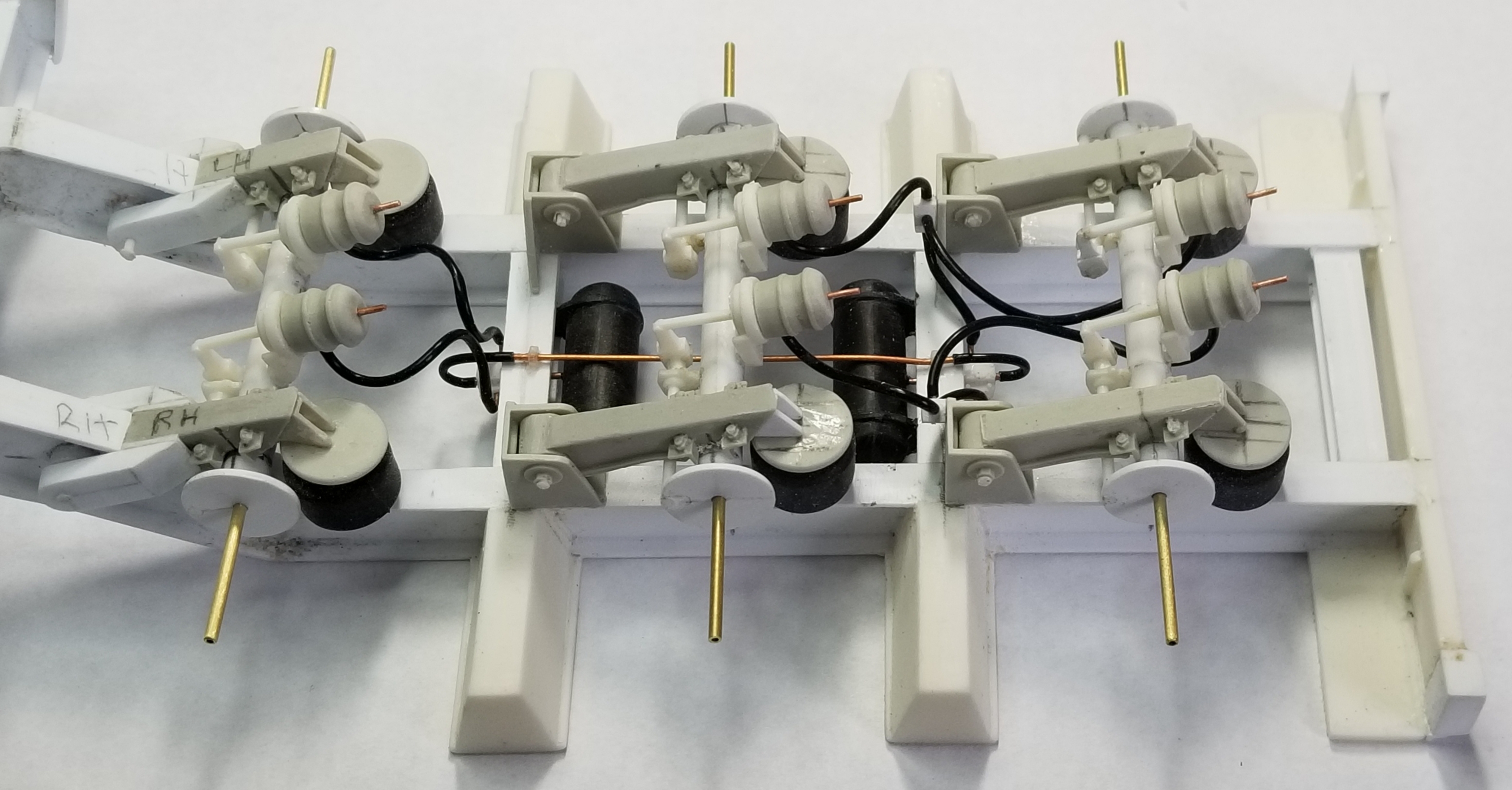
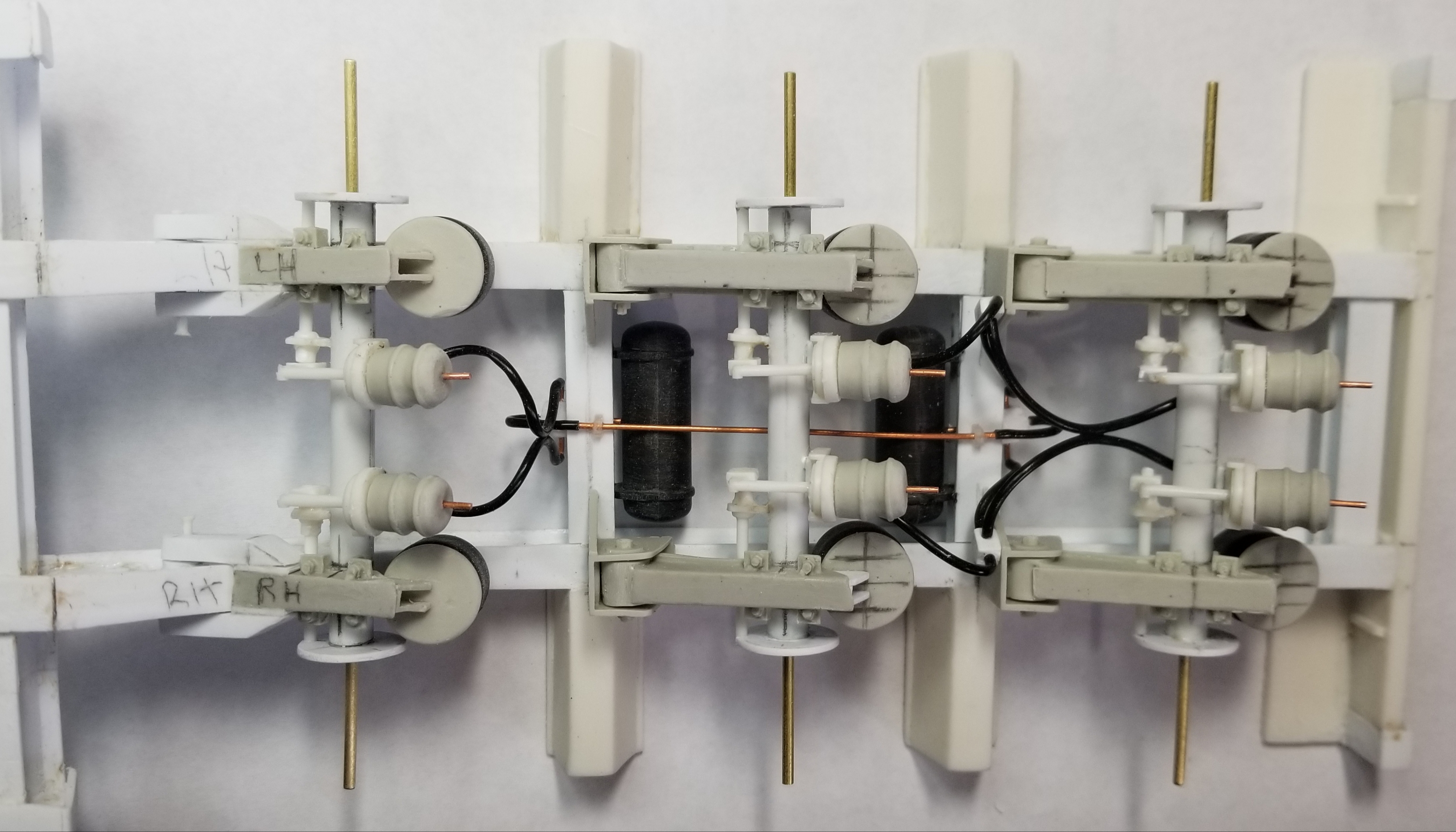
Hey guys
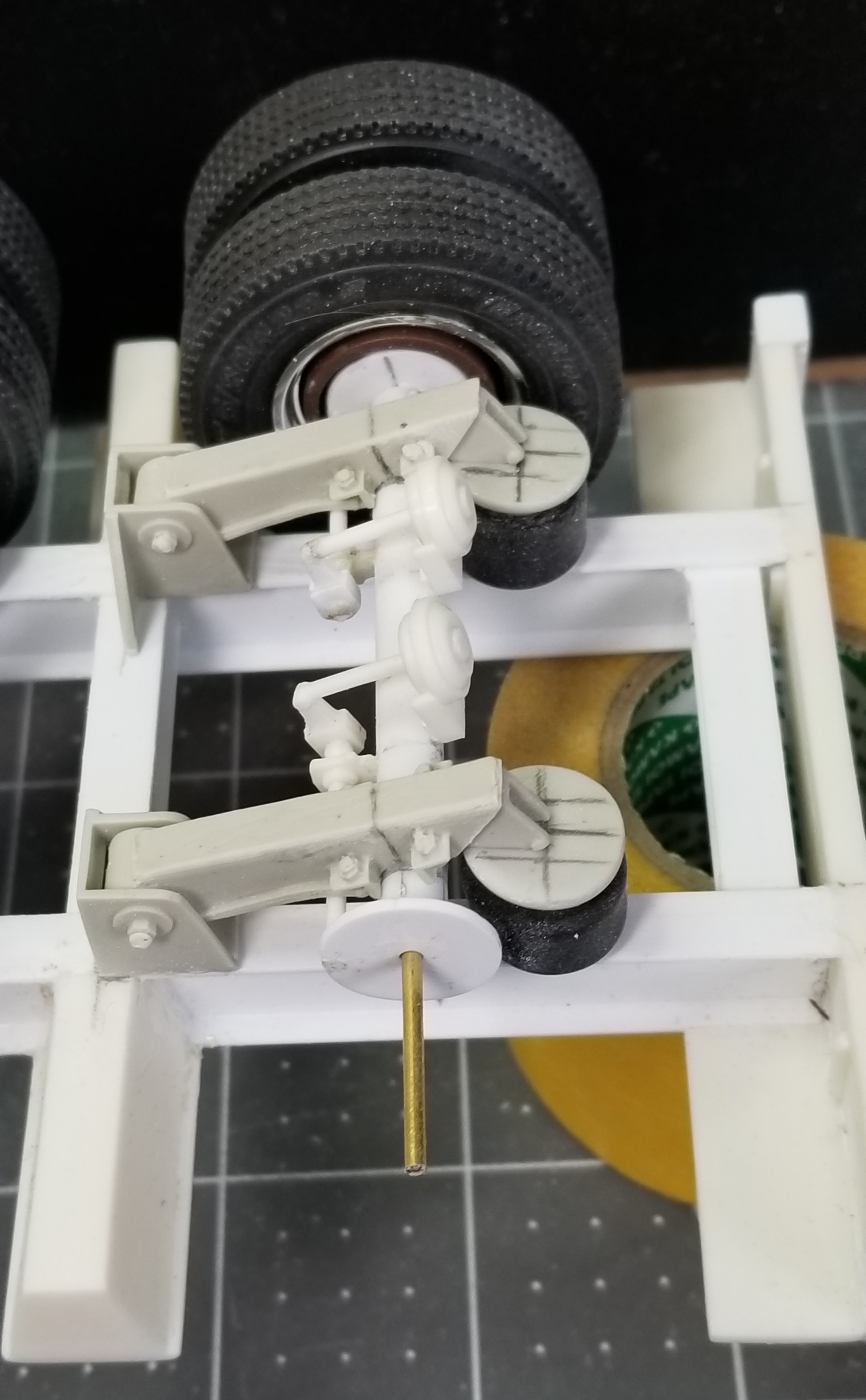
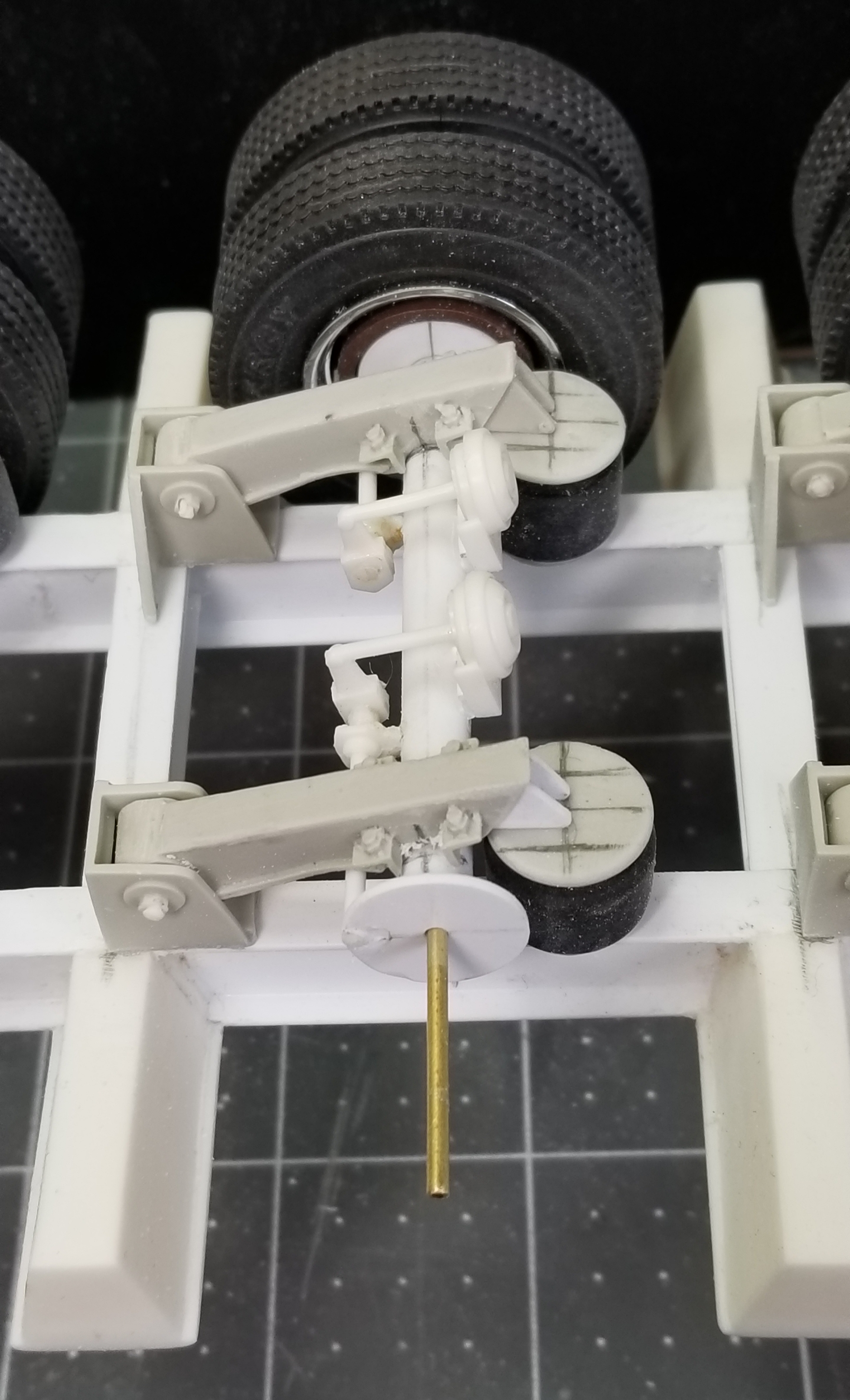
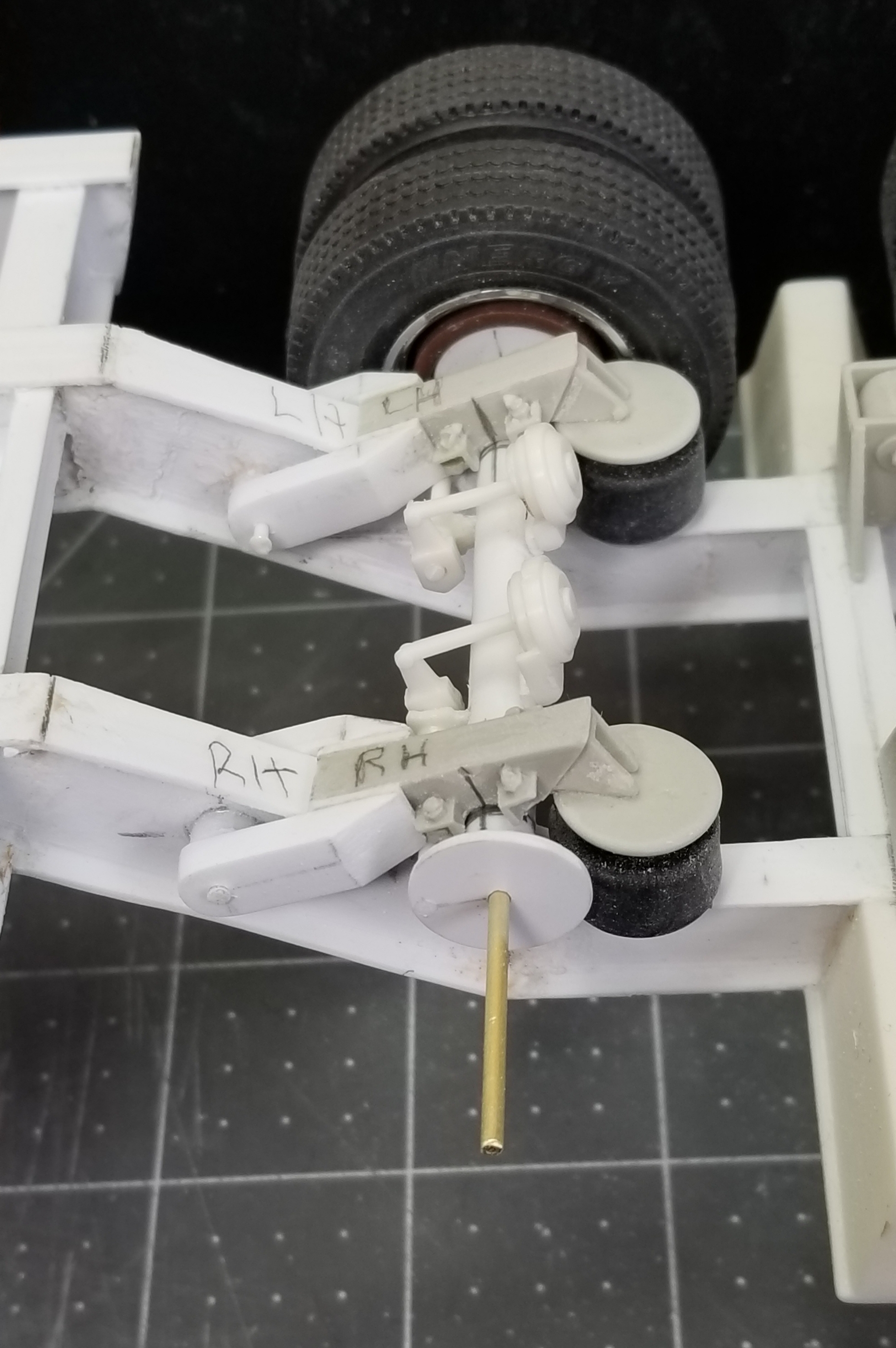
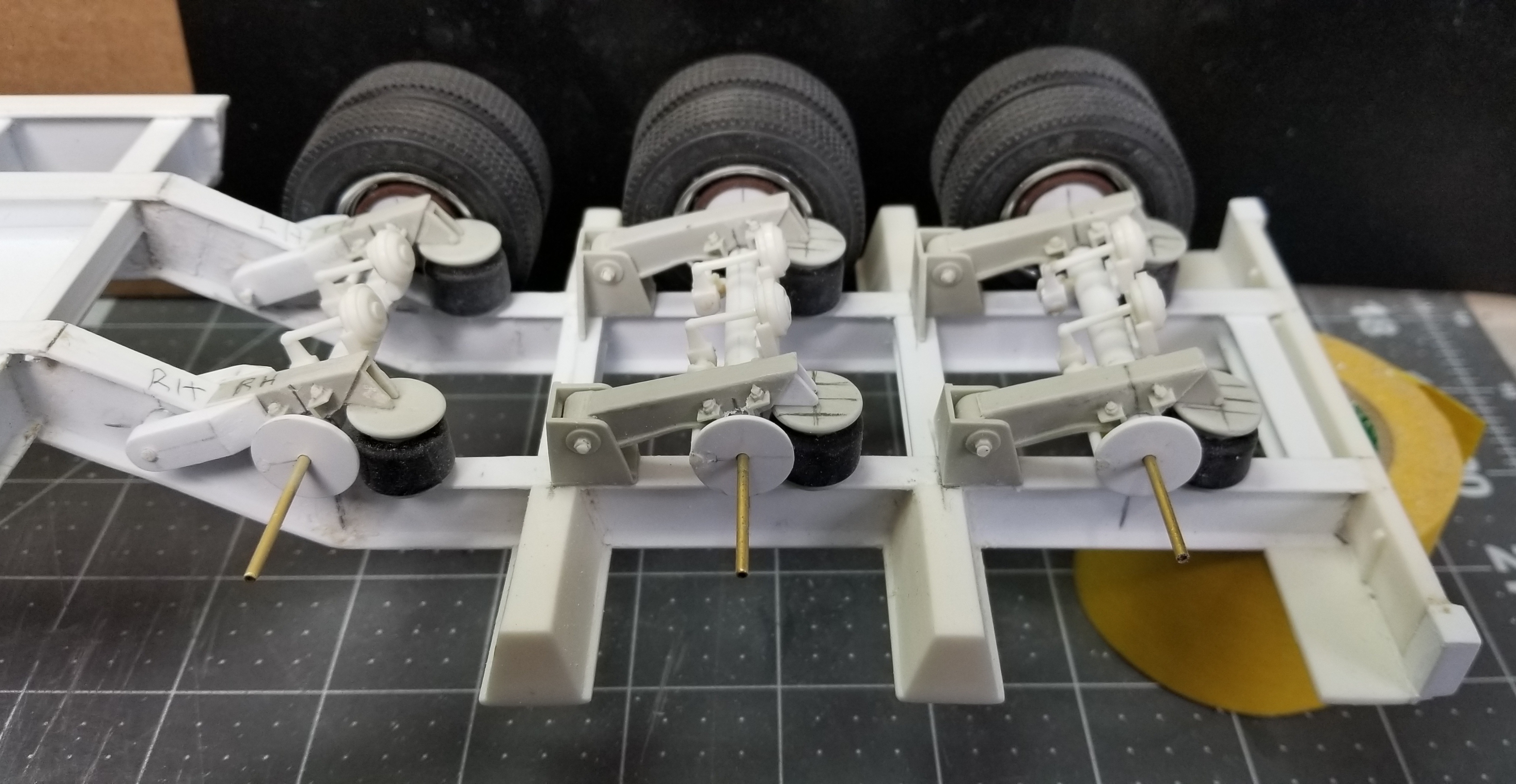
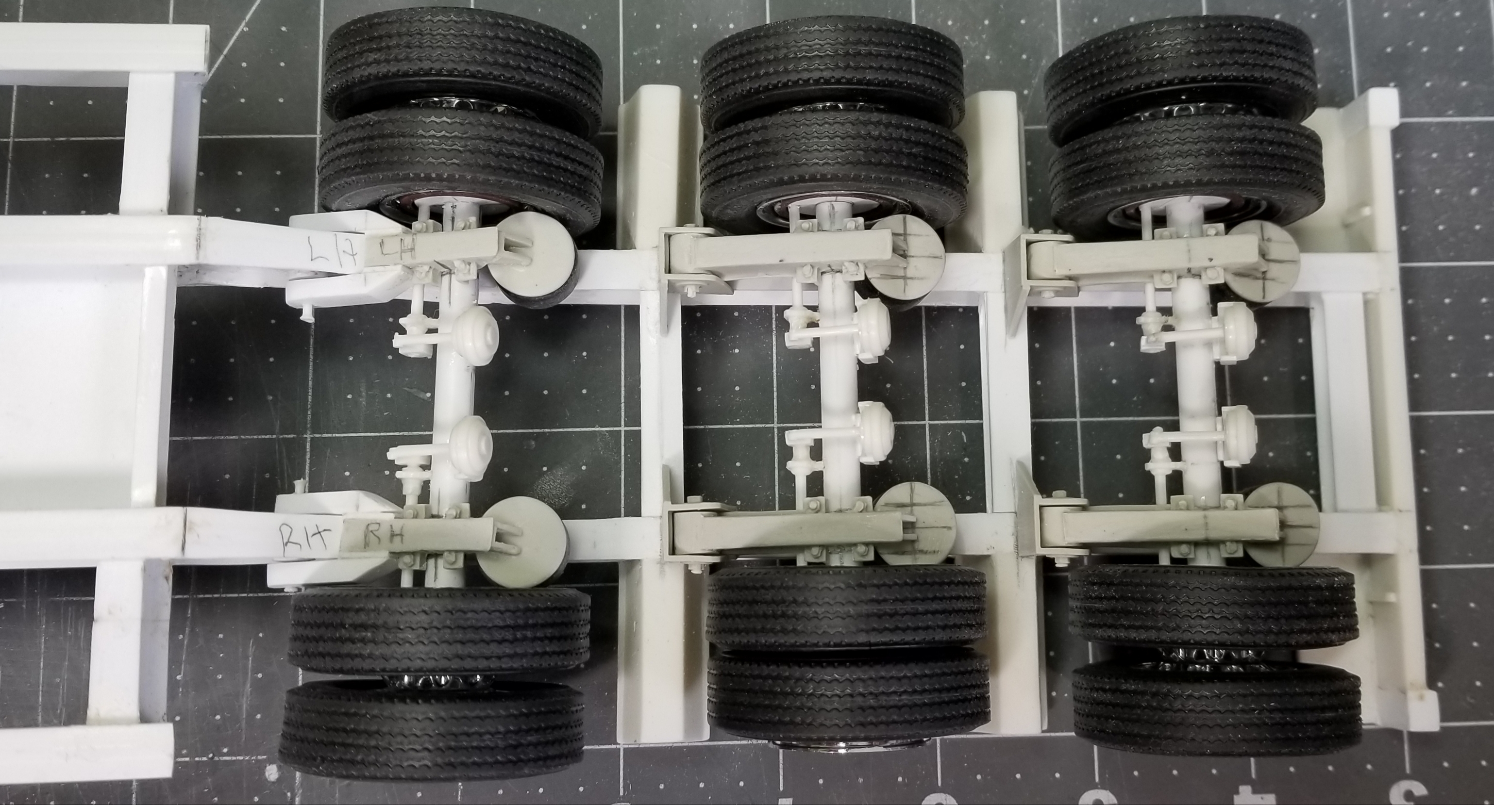
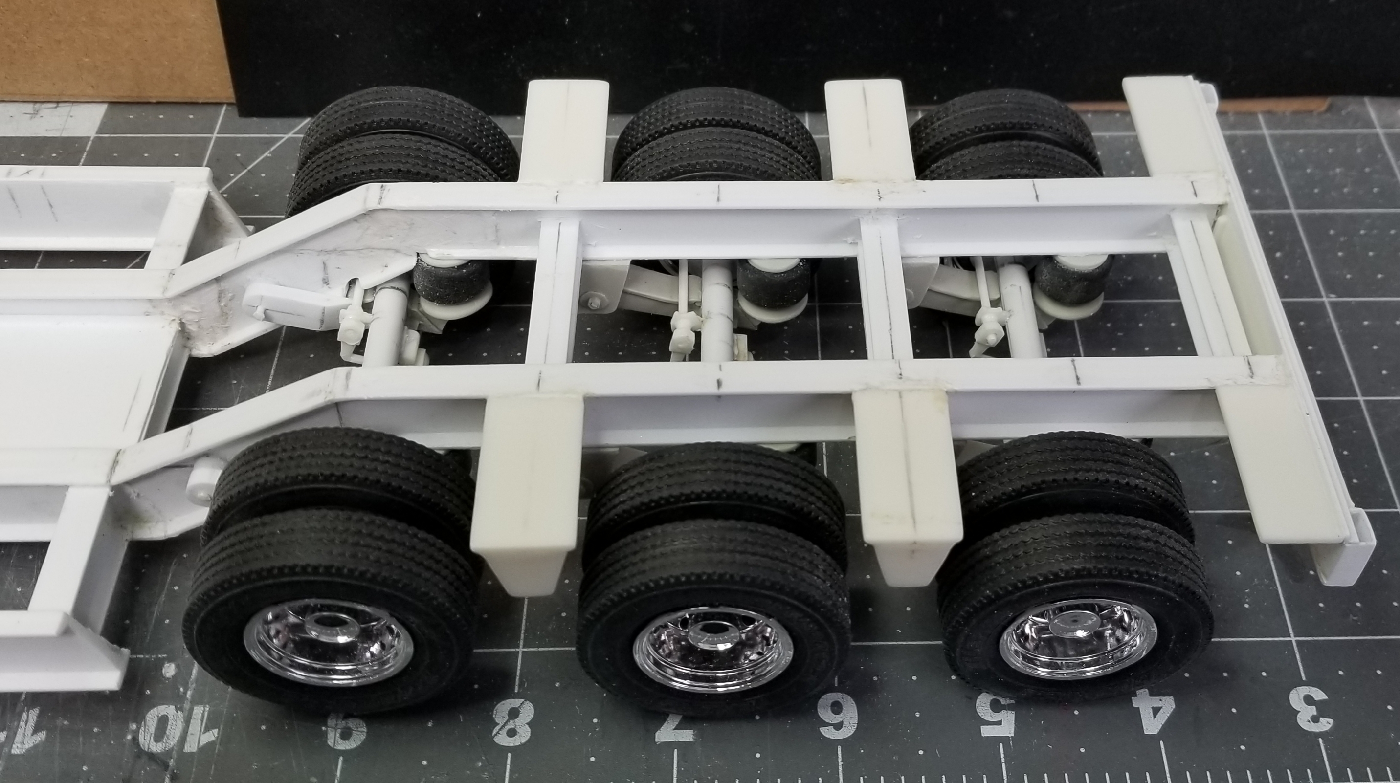
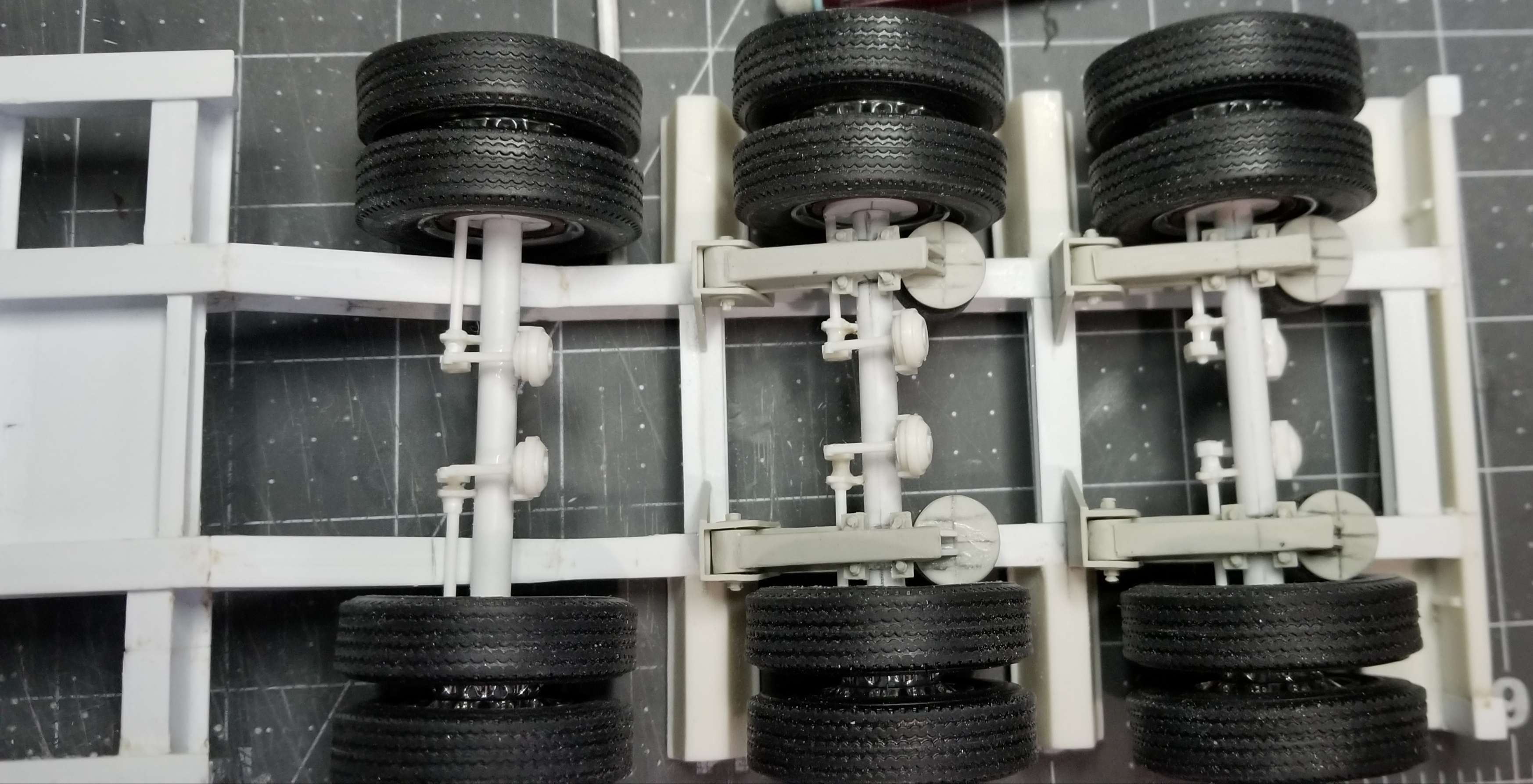
I got the rear axle situation fixed and the front air suspension arms modified to fit around the trailer frame.
this view shows the rear axle with the air brakes now on the correct side. duh!
this view shows the center axle.
this view shows the front axle and the modifications I had to make to the frame and the Moluminum parts so that they fit around the trailer frame.
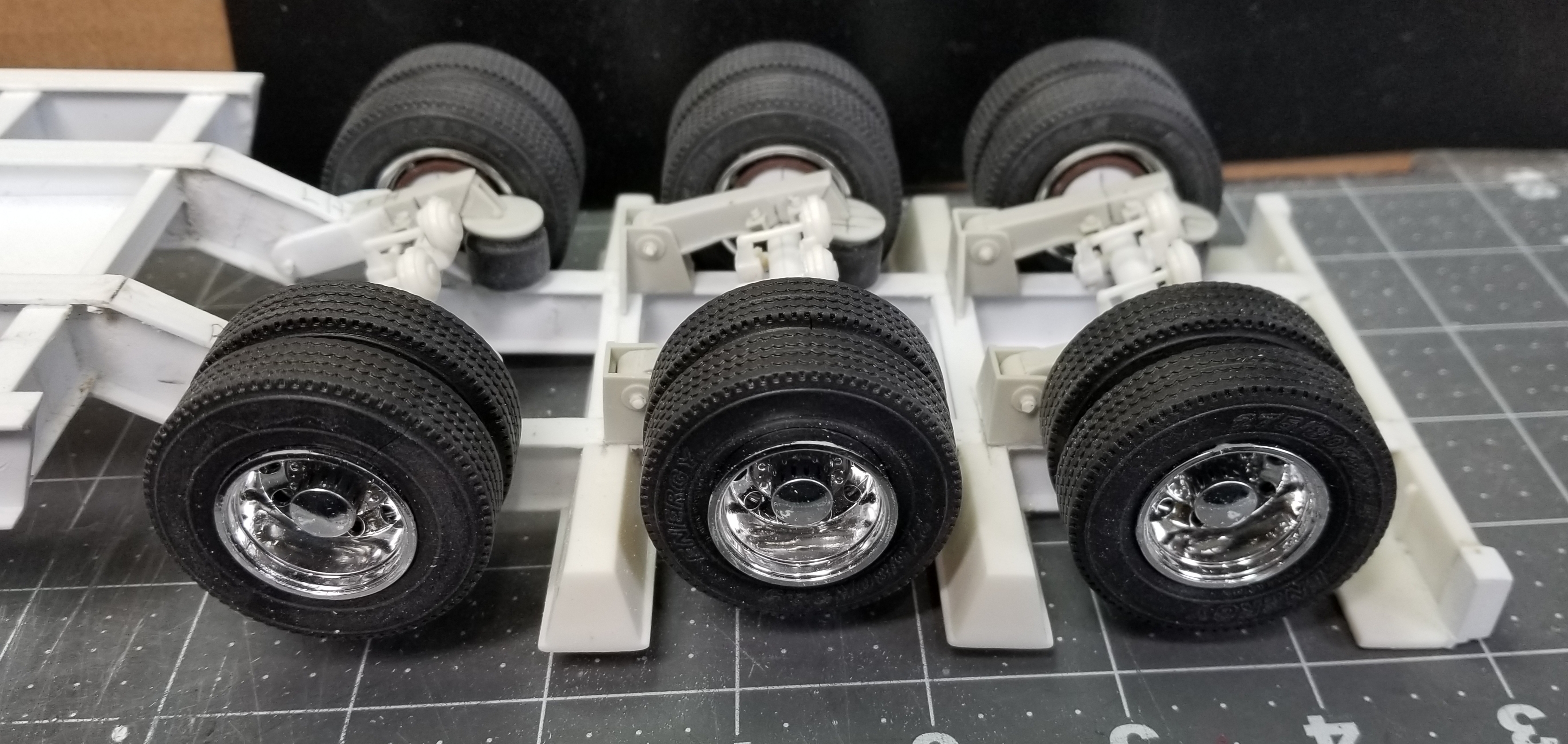
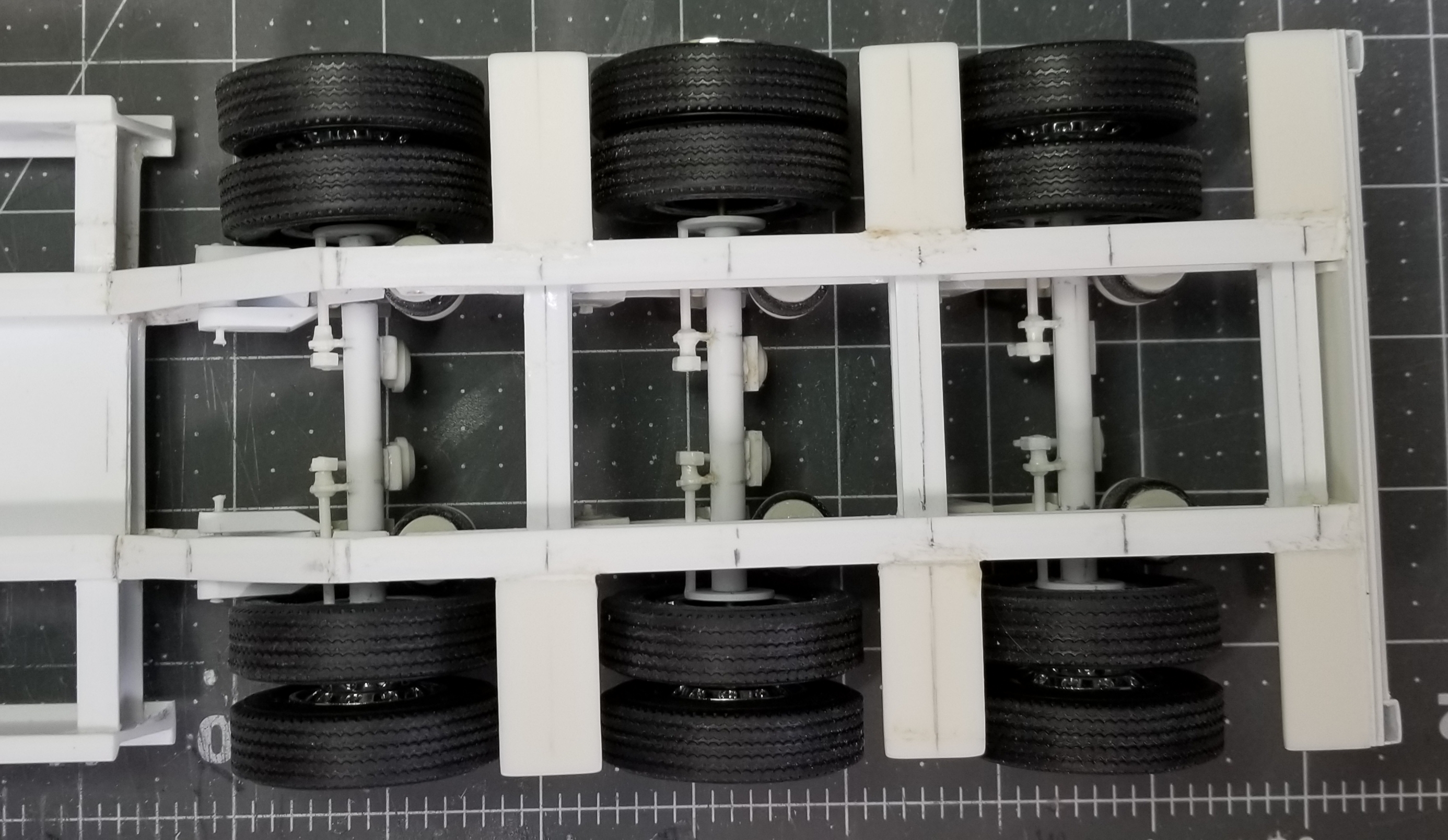
this view shows all of them.
this view shows all of them with the wheels/tires added on.
view of the bottom if the trailer rear.
view from the top of the trailer rear.
side view of the rear of the trailer.
this view shows the trailer sitting on my Kenworth W925 and the Cat 374FL on it for perspective. I ordered some more Moluminum air suspensions for the jeep and the stinger/booster, so until I receive them in the mail there on hold. well that's it for now be back with more updates soon.
duh!
this view shows the center axle.
this view shows the front axle and the modifications I had to make to the frame and the Moluminum parts so that they fit around the trailer frame.
this view shows all of them.
this view shows all of them with the wheels/tires added on.
view of the bottom if the trailer rear.
view from the top of the trailer rear.
side view of the rear of the trailer.
this view shows the trailer sitting on my Kenworth W925 and the Cat 374FL on it for perspective. I ordered some more Moluminum air suspensions for the jeep and the stinger/booster, so until I receive them in the mail there on hold. well that's it for now be back with more updates soon.
Ron G
-
Hey guys
Here's another update for you all. I received some 3D printed air suspensions from Shapways, but I guess I s#%*^ed up and got ones for a regular height trailer, not a lowboy. It would have been way to much work to rework them, so I went on line and looked around to see what I could find that might work. I went to Moluminums site and found just what I needed.
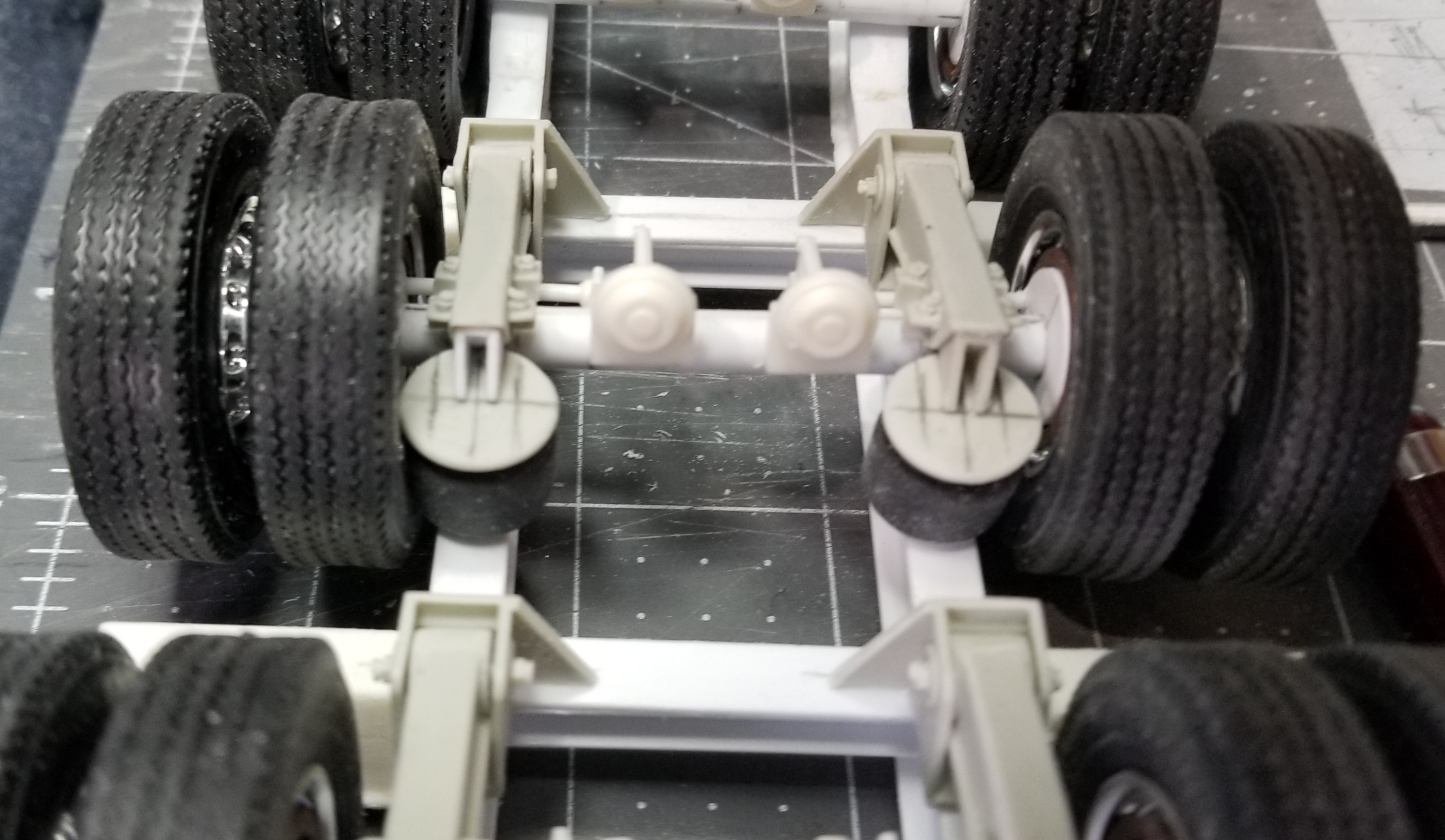
this view shows the air suspension in place on the trailer. All that needs to be done now is add the shocks.
another view of the air suspension from the rear.
this view shows all the axles...WHOOPS!!!...

 I put the axle on the rear on upside down...#^*•☆... BLAH_BLAH_BLAH_BLAH! Well tomorrow I'm going to have to fix it. This was not a good day, from the first part I dropped on the floor, to the second, to the third, etc., etc. to messing up the axle, so I decided to give up and go eat dinner.
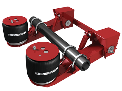
this view shows the real suspension that the model parts copy, Hendrickson 30ton. Well that's it for now be back soon.
I put the axle on the rear on upside down...#^*•☆... BLAH_BLAH_BLAH_BLAH! Well tomorrow I'm going to have to fix it. This was not a good day, from the first part I dropped on the floor, to the second, to the third, etc., etc. to messing up the axle, so I decided to give up and go eat dinner.
this view shows the real suspension that the model parts copy, Hendrickson 30ton. Well that's it for now be back soon.
Ron G
-
29 minutes ago, Mopar - D said:
Ron again thanks for sharing your scratch building skills for us here your progress is awesome. Are you planning to weather the excavator a little?
Most definitely! Along with the trailer, jeep, booster and tractor. Right now my biggest concern is the decals that I need for the excavator, XL trailer and Peterbilt 359 tractor, any ideas?
Ron G
-
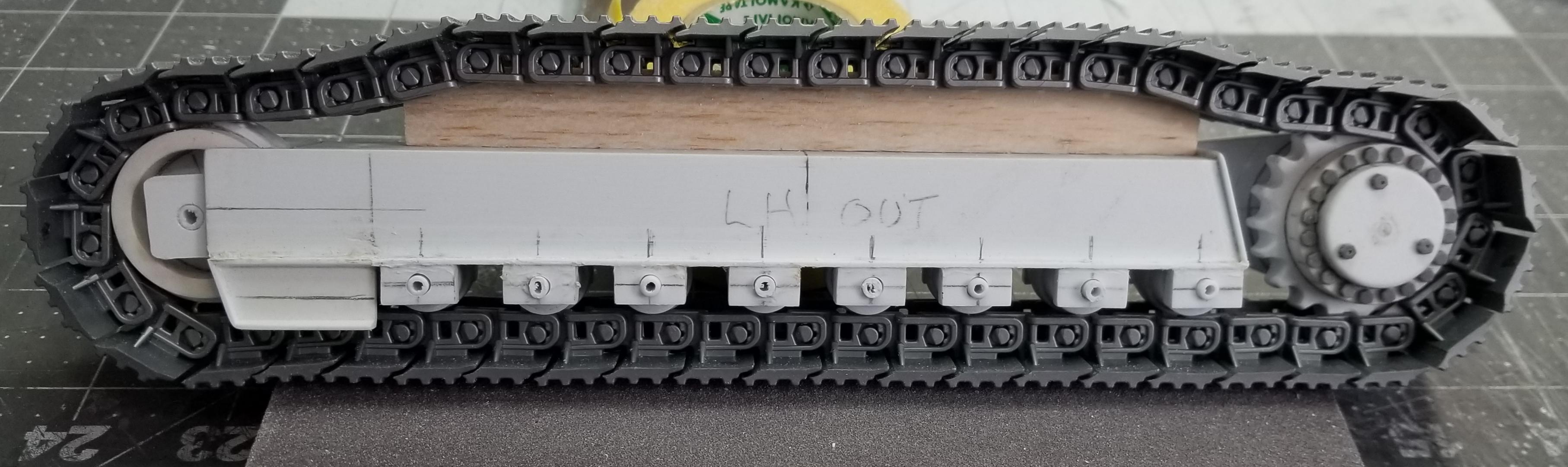
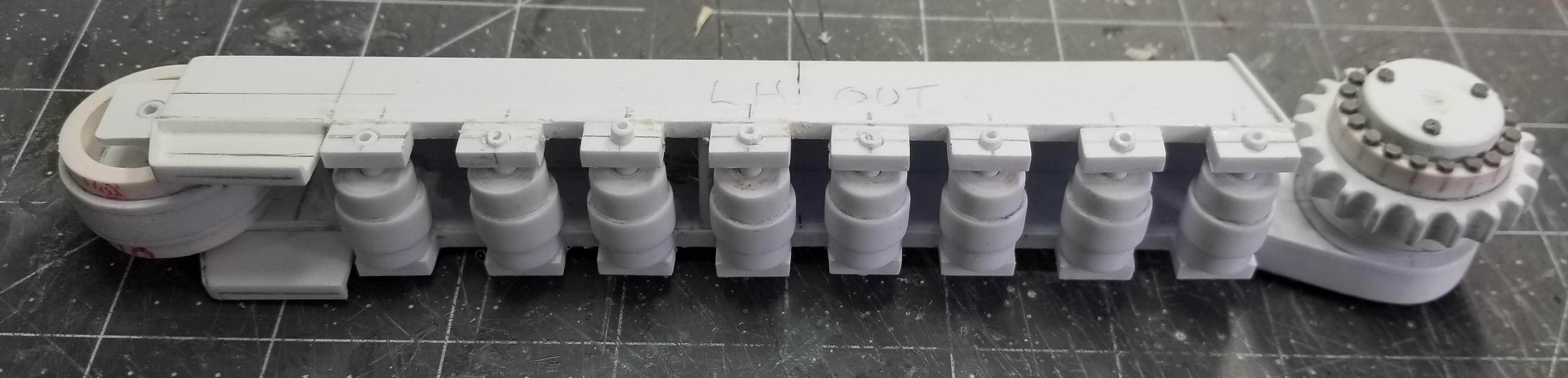
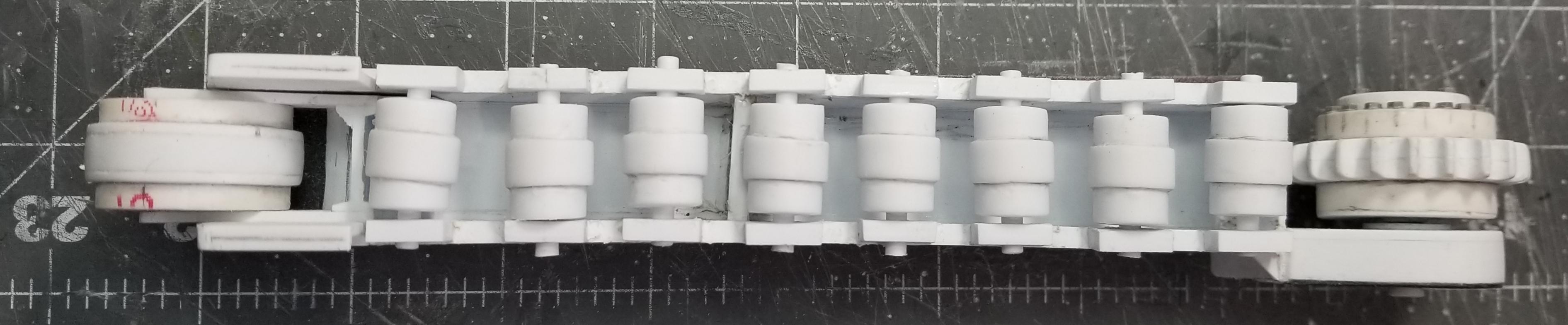
Hey guys
Small update for you all. I have the lower rollers and the upper rollers done for the left hand side of the undercarriage frame.
I took this photo early in the day before I added the upper rollers to it.
this view shows the lower rollers and their mounting brackets.
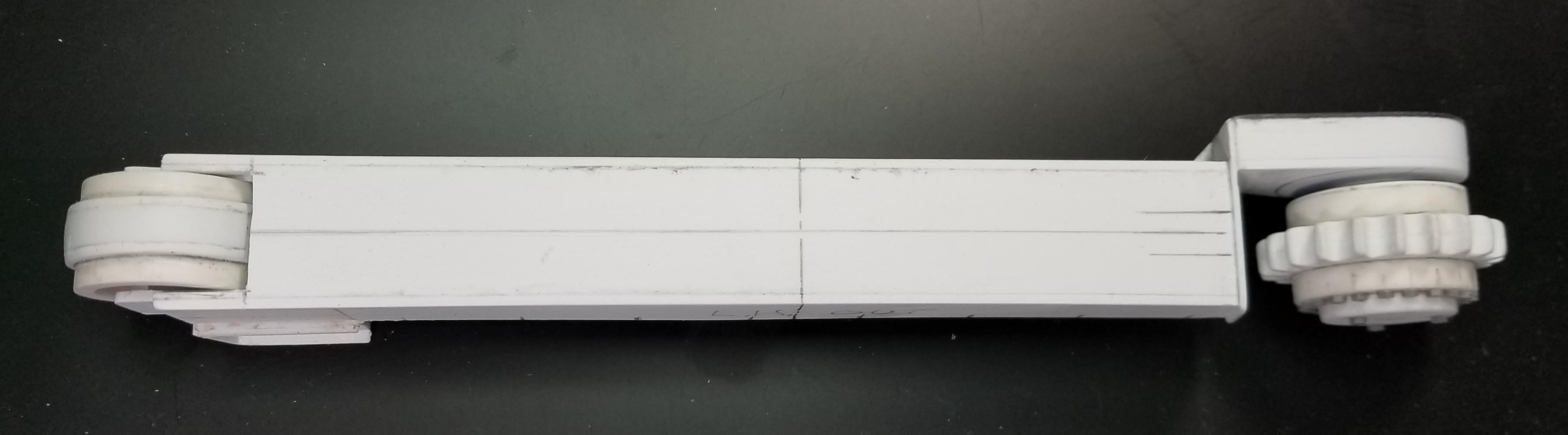
view from the bottom of the LH frame.
this view shows the upper rollers and their mounting brackets.
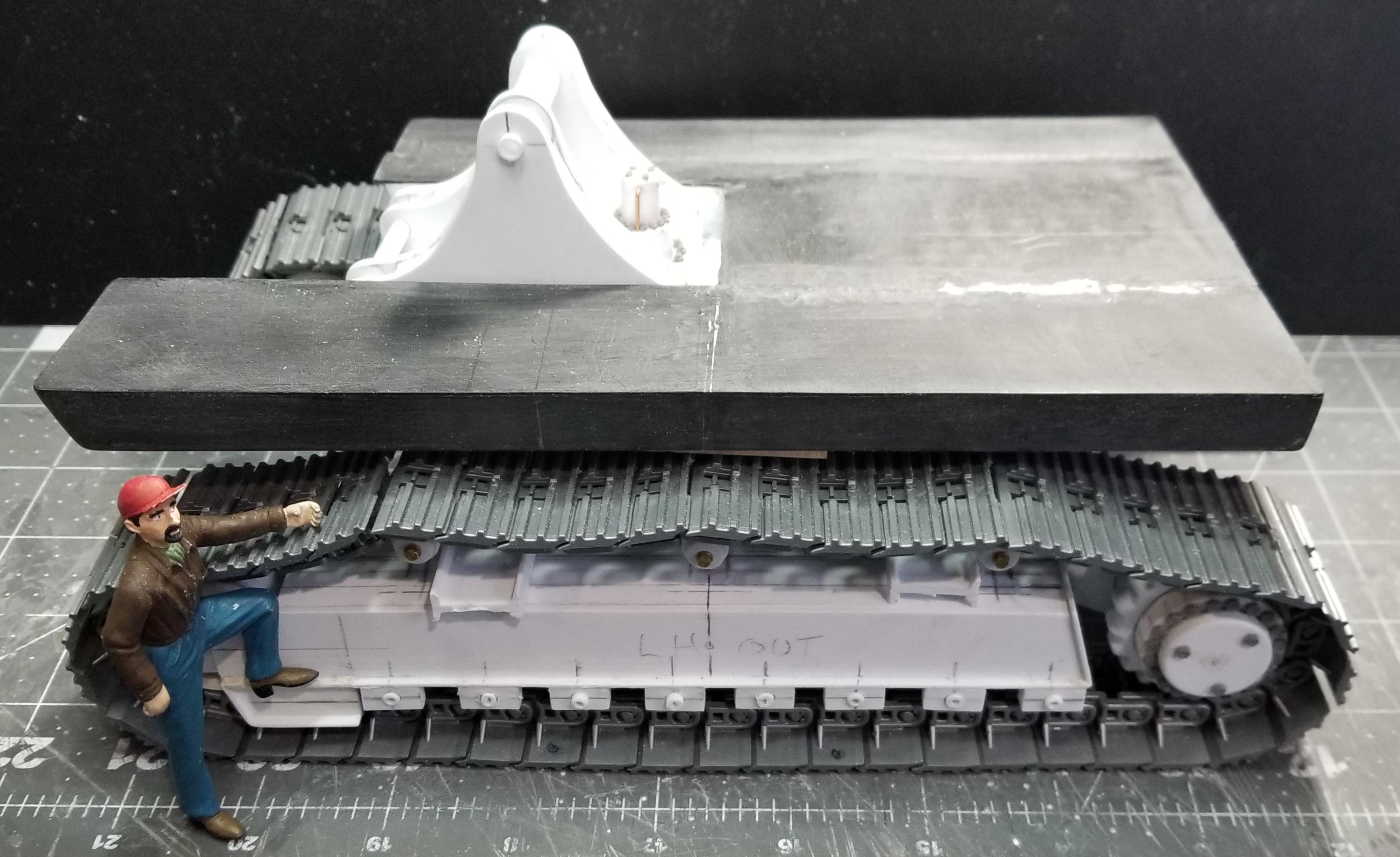
this view shows the body base sitting on the undercarriage. I added my custom made figure to this picture for some perspective. Well that's it for now be back soon.
Ron G
-
Hey all
I now have the two undercarriage side frames about half way done.
this view shows the LH side frame.
same thing from the other side.
top view of the LH side frame.
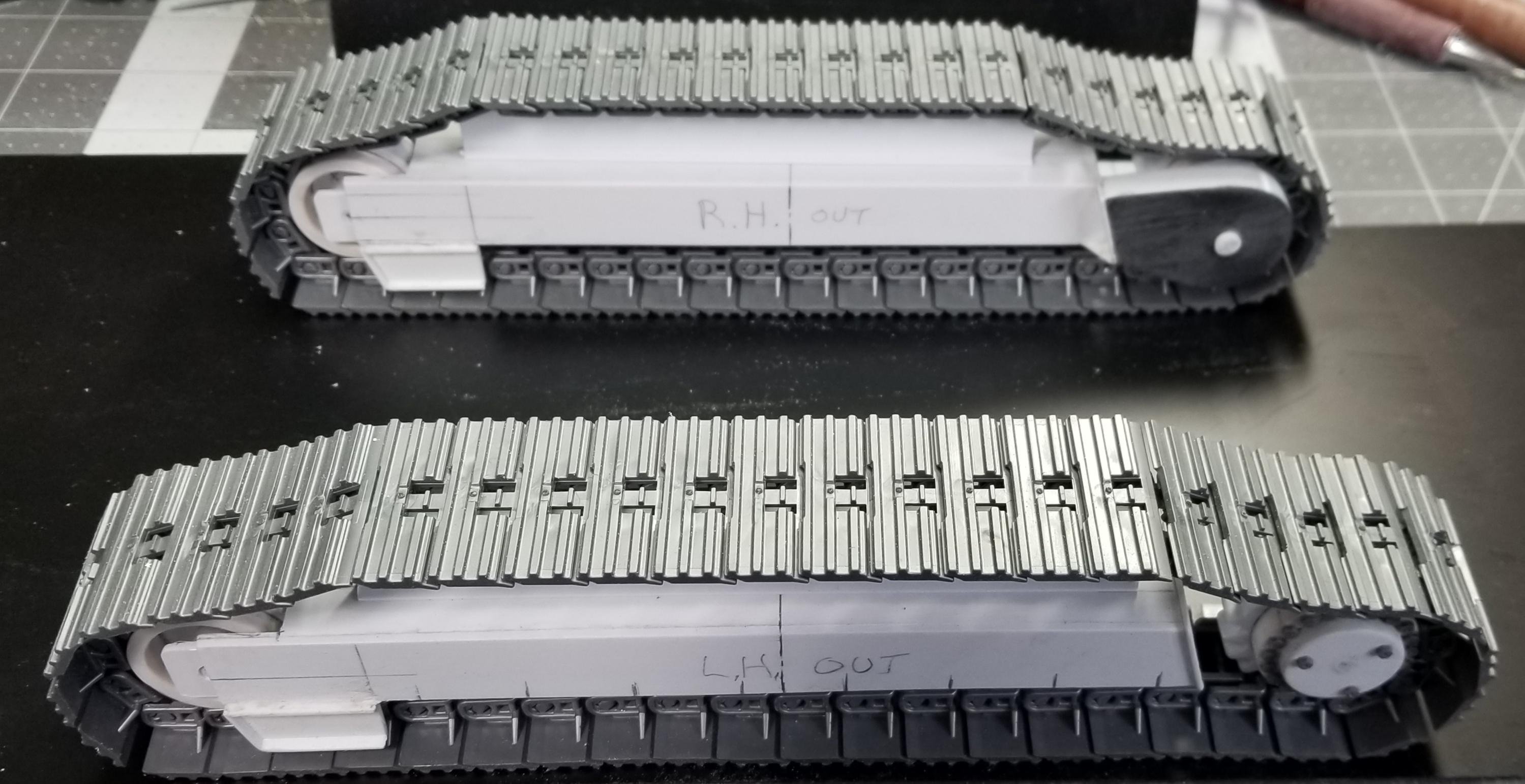
this view shows both the LH & RH side frames.
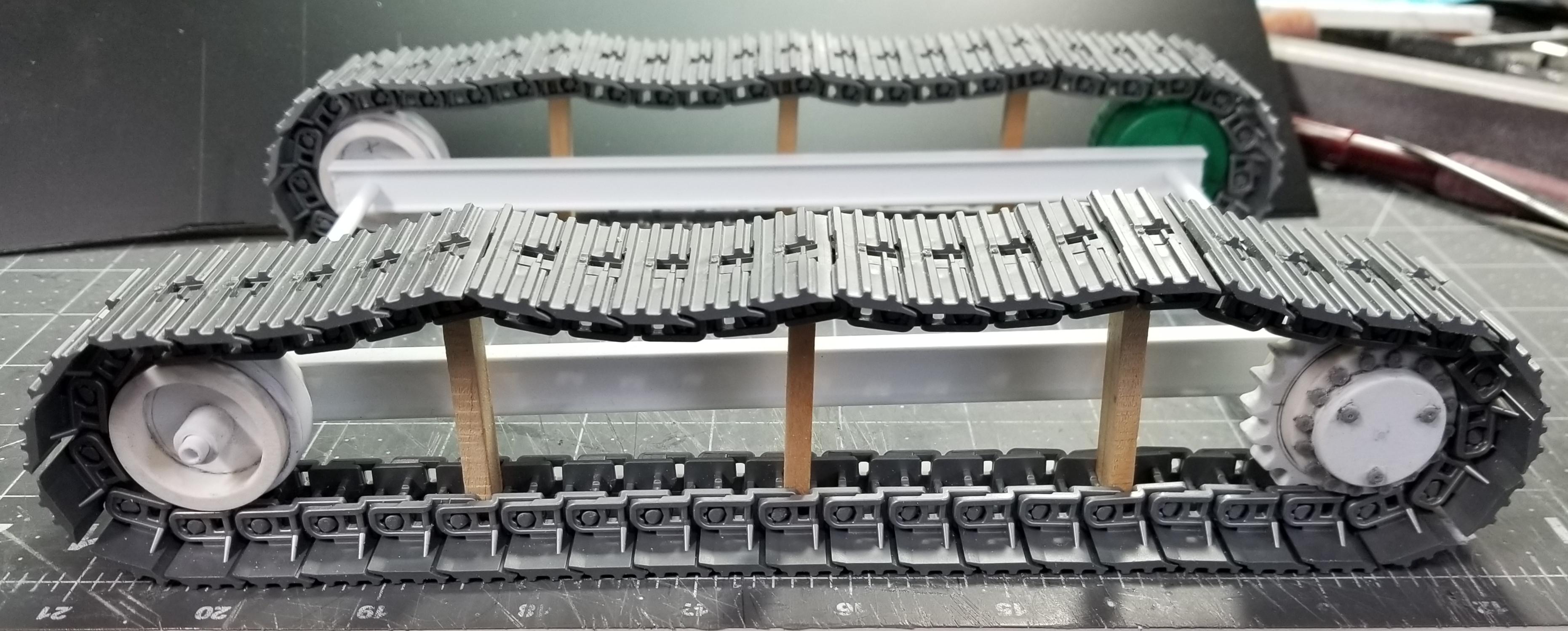
this view shows them with the tracks added.
this view shows them with the base frame in place. I still have to make the 3 upper rollers and the 8 lower rollers and there mounting brackets for both sides, plus the 2 steps on each side frame, both sides and the main center section that attaches to the 2 side frames and the main base frame together, plus all the bolt heads...🤪...Yicks! well that's it for now be back soon with more updates.
Ron G
-
-
-
9 hours ago, Mopar - D said:
Ron that’s all you did. Lol that’s awesome work and thanks for the step by step process. You should make a resin cast for future builds. Looking forward to seeing more details.
Yeah, probably not going to make resin castings, but I may make them on my 3D printer.
I have both sprockets done now, time to start on the undercarriage frame.
Ron G
-
Hey all
Another update for you all. I have one of the drive sprockets done.
this view shows the idler and the drive sprocket. I made this from the same 3/4" diameter PVC pipe that I used for the idlers. I made the sprocket teeth from some 1/8" thick plastic sheet glued together to make it 1/4" thick. I then ground out the center of the teeth to the OD of the pipe. I then drilled out the notches for the track link pins, all 20 of em, then I sanded the OD of the teeth to the correct size diameter. I then made the inner peice out if three peices of plastic sheet glued together to make it 0.18" thick, then sanded it to the ID of the pipe and glued it to the center. I then made a peice for the outer edge out of some 1/8" & 1/32" plastic sheet glued together and then glued to the outer edge of the sprocket. To this I added some 2.6mm Meng bolt heads (20 of em, plus three) and voila you get a drive sprocket...lol
more of a side view of them.
end view of the idler and the sprocket.
view of them next to a scale.
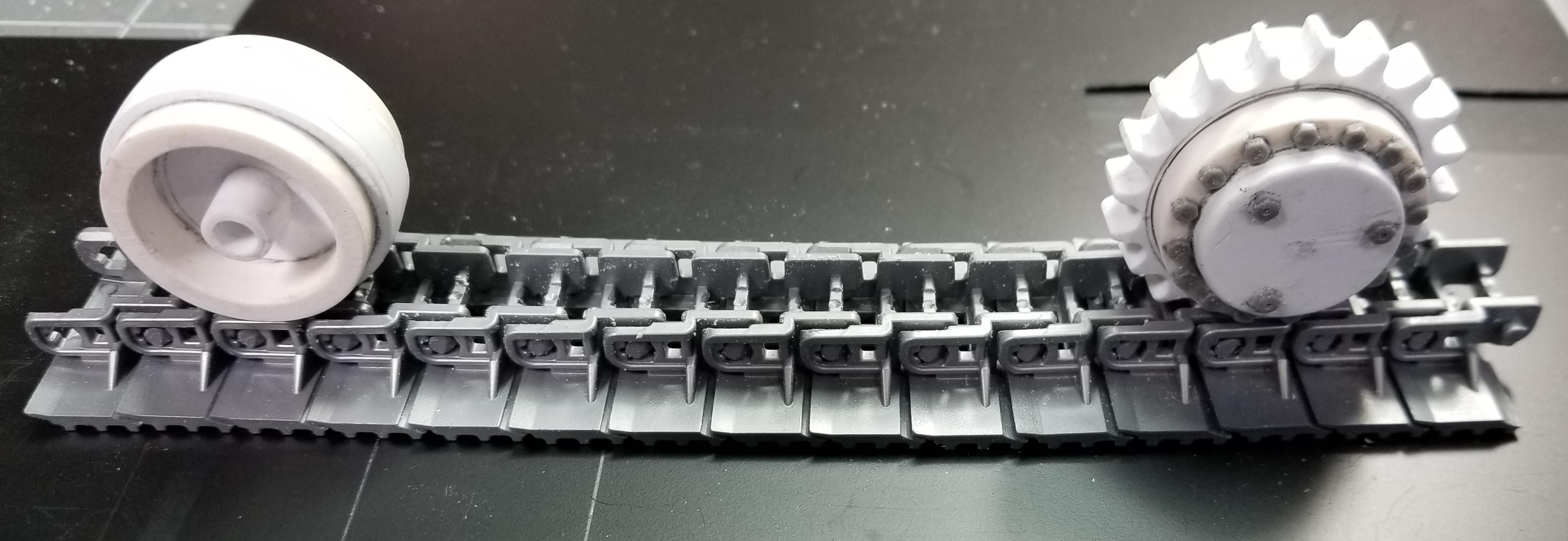
this view shows them sitting on a piece of the track links.
this view shows the idler and the drive sprocket in place on the tracks. Well that's it for now be back with more soon.
Ron G
-
Hey all
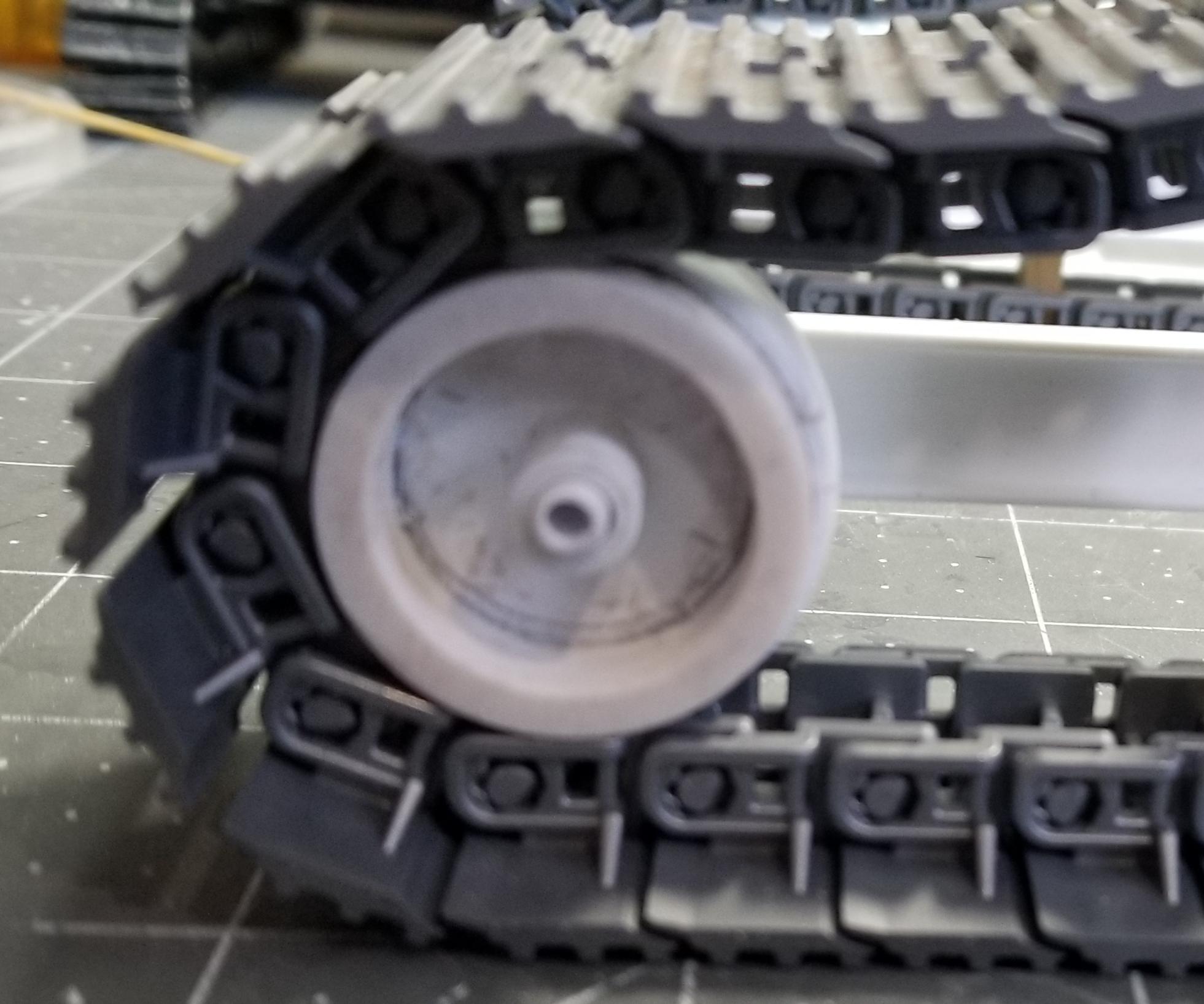
Small update for you all. I have the idler wheels done.
here is the idler wheel in place on the tracks. I made this from a piece of 3/4" PVC pipe that is 1.07" O.D. which is 26.75" diameter in 1/25th scale. I then added some plastic strips to the center of the wheel for the track guide, then some 7/32" & 9/32" plastic tubes for the hubs. This will be spring loaded in the undercarriage frame to take up slack in the tracks.
this view shows both of the idlers.
this is were I'm up to at this point. It doesn't look like much but it was a real challenge to figure out and build. Well that's it for now be back soon.
Ron G
-
Hey all
Well today started off like every other day. I went down to the model bench to start working on the 374 excavator. I started drawing the rear view in order to get the counter weight right, when I realized I messed up...🤬😤. I made it to narrow! I made it 9' 0" wide which put the boom pivot bracket off center, plus it just looked to narrow, so I made it 10' 6" wide with a 10' 0" track gauge instead of 9' 0" that I had it. It looks better and way more proportional now.
this view shows the newly modified base.
top view of the new base, way more proportional now.
bottom view of the base, you can see the piece I had to add to the middle of the base.
this view shows the boom pivot bracket sitting on the base. Hopefully I won't mess up again...yeah, right who am I kidding...lol
Ron G
-
Thanks Mopar
I try to show as much as I can so anyone interested in trying can use my posts to help them build one of there own. If anyone wants any extra information please just ask, I'll be glad to help.
I'm not getting any younger and I won't be around for ever, so any help I can pass along to the younger/or inexperienced builders the more I'm doing my part to keep our hobby going.
Ron G
-
-
Hey guys
Another update for you all. I've done some more work on the base. I added the main pivot bearing surface to the bottom of the base. I made a pivot pin piece that will actually become part of the undercarriage frame. I also have both of the 2 swing motors done.
this view shows the bottom of the base with the bearing surface added.
this view shows the bottom of the base with the pivot pin for the undercarriage sitting in place.
this view shows the boom pivot bracket, pivot pin for undercarriage and the 2 swing motors.
this view shows the pivot pin piece.
top view of the swing motor.
side view of the swing motor.
this view shows both of the swing motors. I had to grind the bottoms out of some 1/8" thick plastic sheet glued together to make it 1/4" thick. The rest is made from 1/2" & 5/16" plastic tube with some 0.03" thick plastic sheet top pieces. The bolt heads are from Meng, 2.2mm and 1.8mm heads. These you have to individually cut off of the plastic piece they come on. Then glue each one (36 of em) on to the motors. Then I added some brass wires for pipes and hydraulic line connections.
this view shows the 2 swing motors in place on the boom pivot bracket.
this view shows the boom pivot bracket sitting in place on the base.
top view of the whole thing sitting on the tracks. Well that's it for now be back with more updates soon.
Ron G
-
Thanks guys I really appreciate it.
Hey Force Hasagawa makes this one in 1/35 scale.
It's kinda of a smaller one though.
Ron G
 So here are some pictures for you all to perose.


48' Loadking 3 axle drop nose lowboy trailer
in WIP: Model Trucks: Big Rigs and Heavy Equipment
Posted
Hey guys
Small update. I did some more work on the booster/stinger.
Ron G