Sluggo
-
Posts
10 -
Joined
-
Last visited
Content Type
Profiles
Forums
Events
Gallery
Everything posted by Sluggo
-
3D printed Frames Question
Sluggo replied to Oldmopars's topic in Truck Aftermarket / Resin / 3D Printed
Yes I plan to incorporate cross members. It looks like only the simple ones are needed in the stretch area. The snow plow kit has extra cross members in it so I can model them up pretty easily or even just alter the kit parts. In the process of converting the LNT-8000 frame for use as an LT-9000, I discovered that the Italeri LTL-9000 frame is just wrong. Most LTs and LTLs had the 13 inch straight rails. So that kit will need a corrected frame if I ever get around to it. I'm test printing the wrecker body and mast now to dial in the thicknesses. I will start a build thread when I get some positive results. I'm dead set on taking this thing to the Nats.
-
3D printed Frames Question
Sluggo replied to Oldmopars's topic in Truck Aftermarket / Resin / 3D Printed
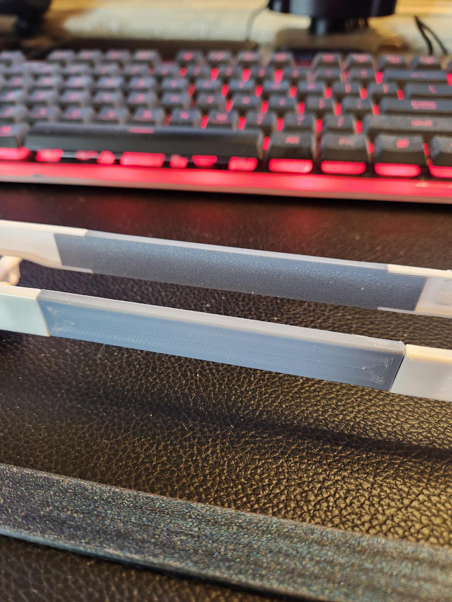
After modeling a full frame rail for my wrecker project, a stretch kit opposed to full frame rail would negate the need to model or print any lumps, bumps, rivets, holes.etc. If you use parametric modeling, you could offer on demand custom lengths without the need to make a new model each time. I just finished modeling and printing these inserts earlier today. They fit great and I can't believe how much rigidity they added to the kit frame, even unglued. At 88mm long i was sure they would introduce a sag or floppiness but they did just the opposite. They also cured the bow in the kit parts. Printed in PLA+. he Reason for stretch...
-
Revell Peterbilt 359 (pic heavy)
Sluggo replied to Sluggo's topic in WIP: Model Trucks: Big Rigs and Heavy Equipment
Ok, Here we go. I recently purchased this not knowing it was in fact a snap kit. It looks like it will model up pretty decent in spite of it's simplicity. I am currently working on a Mack DM600 that is beginning to irritate me so I am going to back-burner it and start on this piece. Just a little history on me. I built mainly cars and trucks as a kid then took a 3 decade detour into rivet counter aircraft modeling. The rivet counter days are behind me but I still love a nice paint job. To that end, I had to pick a paint scheme and get some of the design work done before proceeding too far. I thought I'd share my process of drawing and test fitting a mask set. There will be a bunch of pics and they are sized according to their content so they will be different sizes. The first step is to pick a scheme and then import a picture of it into Illustrator to draw vector drawings over it. I chose Late 70s early 80s Peterbilt 026B. Here is a background pic in Illustrator along with what I will refer to as a scale box that is 147 mm long and 52.5 mm high. This box represents the actual size the overall graphic need to be on the model. The sleeper on the truck in the picture is longer than the sleeper on the model but we need to factor in the extra length needed to wrap around the back of the cab and around the front of the sleeper so we will just leave it the length it draws out at to start and address the length after the first test fit. My first thought this is a pretty complex design. After a bit of thought it dawns on me that this can achieved with only two shapes using translucent colors or transparency if you will. Here I draw the first shape using the pic as a background. The pic is not a dead on profile so you might notice my drawing is a bit off from the picture. I am forcing my lines straight and parallel. Second shape drawn. Note that you can already see the third color where the red shape overlaps the yellow. Here is the two shapes drug off of the background pic. This shows the contrast a little better also. I have to break here to get some other work done. I'll edit and add more later.
-
Sorry, Had to purge this post. Something went terribly wrong with the pics. I'll try again tomorrow.
-
I can appreciate and completely respect that! Thanks for sharing the finished pictures!
-
Very nice piece of work! I too would like to see progress pics!
-
Like this? https://www.scalehobbyist.com/catagories/Model_Cars/1970-amc-amx/MPC00000814/product.php?s=0&t=11&u=1,2&pg=1&ppp=48&sb=stocknumber&so=a&sc=20
-
1969 A12 Roadrunner (I will need some advice)
Sluggo replied to Brutalform's topic in WIP: Model Cars
Great Build!