Egilman
-
Posts
80 -
Joined
-
Last visited
Recent Profile Visitors
1,356 profile views


Egilman's Achievements
MCM Regular (3/6)
-
Will do Alan, Only thing I can do at this point is sleep, or it seems like it... Time to go take a nap, just a few words on a keyboard wears me out.... I fear it's going to be a long road back... Elmer
-
Thank you Brother, If I had been awake over the last few months, I would have worried myself... {chuckle}
-
Hi guys, well I'm still kicking... (although it was a fight for a while I've been told) Thanks John for keeping track. life has it's strange turns sometimes... Mr Humble, James, If there is anything you feel like sharing on the Wasp, it would be greatly welcome... Brothers, it's great to be back up and living life again... They say I'm doing great, don't know when I'll be back at it yet, but I'm trying to get there... Time will tell... God willing... EG
-
 Very nice... Great modeling work... Silk purse type stuff... EG
 -
Hi guys, I know it's been a while since I've posted, it's been a while since I worked on the car as well... Problem is I strained my right shoulder about three weeks ago... I'm having a very hard time manipulating the mouse for longer than a few minutes at a time... Barely able to do it enough to navigate the net and forget about designing... (constant mouse use) I've had the x-rays done and am undergoing therapy for shoulder strain, we are trying to see if it is just a functional strain over structural injury... The x-rays I've been told show serious arthritic degeneration... They don't know why, and I don't know what I did to cause it.... But they don't want me using it much till we get some sort of resolution... I'm not giving up on this, The big guy hasn't brought me this far to drop me on my keister... But it seems that the medical issues are piling up on me now... (two year cancer survivor, and now this) I will let you guys know the status of this from time to time, I'm hoping to get back to it sooner rather than later, the big guy upstairs willing of course... Thanks for your understanding....
-
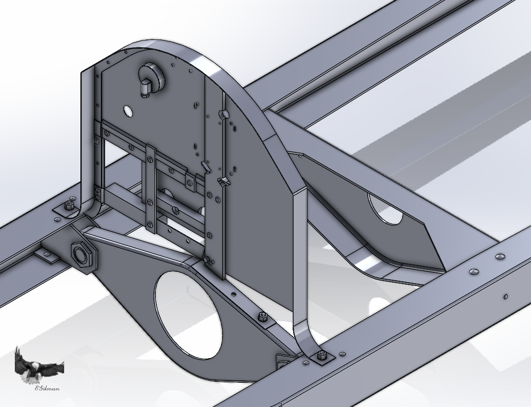
Well it's been almost two weeks since my last update... OH Man!! the forward firewall is another of those brain burners... I'm on my third version.... Front.... It's by no means complete... I still have to figure out the whole left side as far as the cutouts and it resides on two levels it's not flat.... And the back side.... This shows the support structure, (the start of it) for the three transfer gears for the steering... And believe it or not, they are built up wood blocks... The hole cut into them are for access to the nuts securing the transfer gears to their shafts... Also the flywheel will take a decent chunk out of them as well for clearance... Right now I'm sussing out the side brackets and the steering wheel shaft support which is a second frame sitting about a foot farther aft than the firewall, it supports the steering column and the engine controls... (magneto advance retard and the throttle) the holes are all in and the oil pressure gauge is located but I do not have any idea what the ignition switch looks like nor the speedometer.. Yes it had one, but it wasn't hooked up, they would be mounted to the firewall behind the column support... I'm probably going to wing something together to put there on the basis of what should be there, the Bosch ignition switch will be easy, the Warner speedo will not be.... I do not know if it had a clock, most Marmon's did as normal practice but then this was a track only car... Anyway, sorry for the long wait, but I'm still here ready willing and able to bore you to death with the details and my winsome speculations..... Onwards....

-
Hi Steve and Thanks, I"m doin my best... {chuckle} I hope everyone is enjoying my little excursion into reverse engineering... I've never been to the Museum, would like to go sometimes but I think life is not going to allow that to happen... Yeah, a car on all four wheels does look different, like it want's to go go go.... Before that it looks like a bunch of parts looking for a reason to exist... Well I've decided to get to the firewall rather than the brake rods and steering gear, the reason for this is I can design it to fit the pics without having to deal with the parts being in the way... I can do it either way, but having a clear area should work better... And the first step to designing the firewall believe it or not is to build the Radiator... Why? you may ask, cause the shape of the firewall is the exact same shape of the radiator.... The flange of the firewall matches the flange on the radiator and the hood is nothing but flat hinged panels that lay on the flange... The lower panels of the hood have a 90 degree curve that melds the body into the frame and that is shared by the firewall and radiator... So here we go... The first step is the Radiator core support, this is a plate that mounts to the frame rails and carries the weight of the radiator on top of it, it also serves as the radiator locator and the radiator is clamped to it at the lower corners... What it looks like... And where it resides... On top of the core support are two rods that stick up vertically into the radiator core they locate and center the lower tank of the radiator on the chassis... The radiator has two side posts as well riveted to the radiator side tanks to form as side locators, they fit between the core support wings and two clamps that hold the radiator down to the chassis and prevent it from moving around... The Radiator... (with it's clamps in position) And where it resides.... Once the Firewall is done there will be an upper brace rod which starts at the apex of the Firewall and runs from the firewall to the radiator input connection from the engine and provides the upper support to keep the radiator upright.... I will get to that when the firewall is done... (it will be part of the firewall group) Anyway, I'm now able to start designing the firewall since the pattern is now available in the model... Onwards!!!!
-
Another small update... The brake and shift lever.... Yeah I had to redesign it as well, the shift gate and ratchet mechanism had to be completely redesigned... Another step forward... Onwards..
-
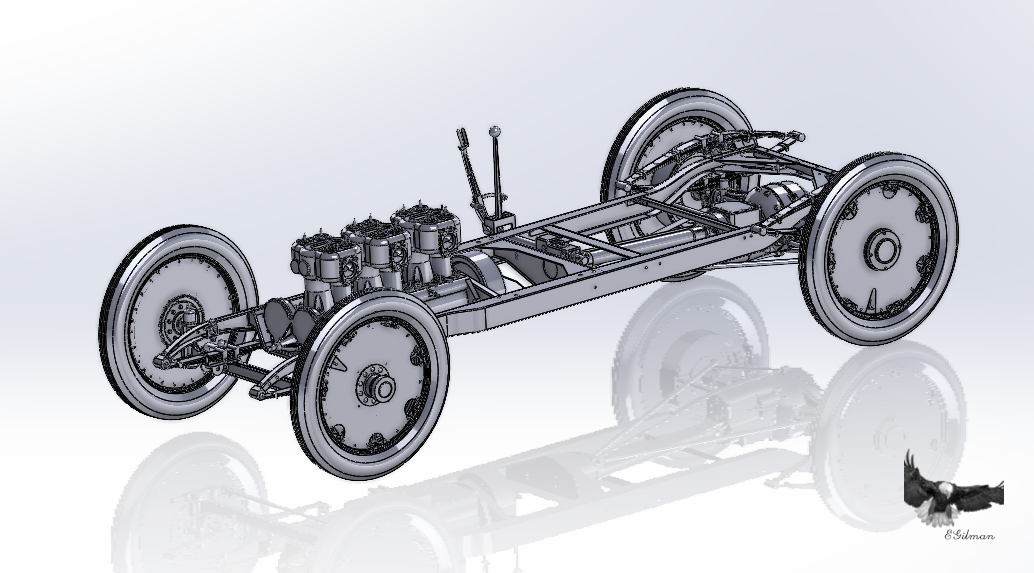
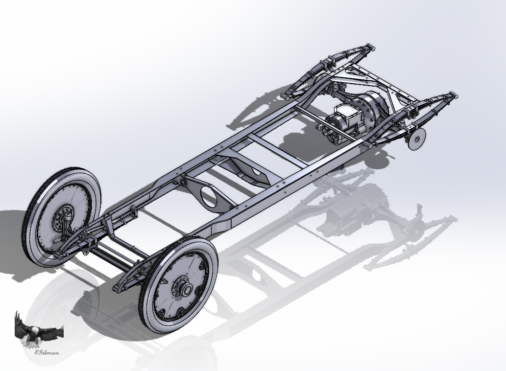
And the rear wheels are on.... And an overall shot.... Had to tweak the Rear Axle and Brakes to work with the wheels, but it was no big issue... Will probably have to tweak them again in the future... Have to make everything fit where it is supposed to fit.... Anyway, ONWARDS!!!! {chuckle}
-
Ok latest update... Was thinking that I could just add the previous brake design with just a little bit of tweaking... Well it didn't exactly work out that way... I could adjust the brake shoes to the correct locations but the rods and levers had to be redesigned.... This is what came out of it... Rear Brake Assembly... Mounted to the Differential Carrier... And within the Rear Suspension Package... You can plainly see where the control levers are back in their natural "off" position and yes the overcenter preventers are there as well... I guess next up would be the Rear Wheels.... Then the Brake/Shift Handles and brake actuating rods.... Onwards!!!
-
Why thank you John!!! It was another little brain burner till I got it understood.... Yeah the internet is pretty sparse when it comes to these automobiles... Anyway the Truss Rods and Braces are done now.... This completes the rear suspension... Next up, getting her some Brakes and Rear Wheels.... The brakes shouldn't take too long as I was pretty close on the last iteration and just need to add some missing details, and the Wheels are done already like the front wheels, but need the brakes to locate them in the model... Onwards....
-
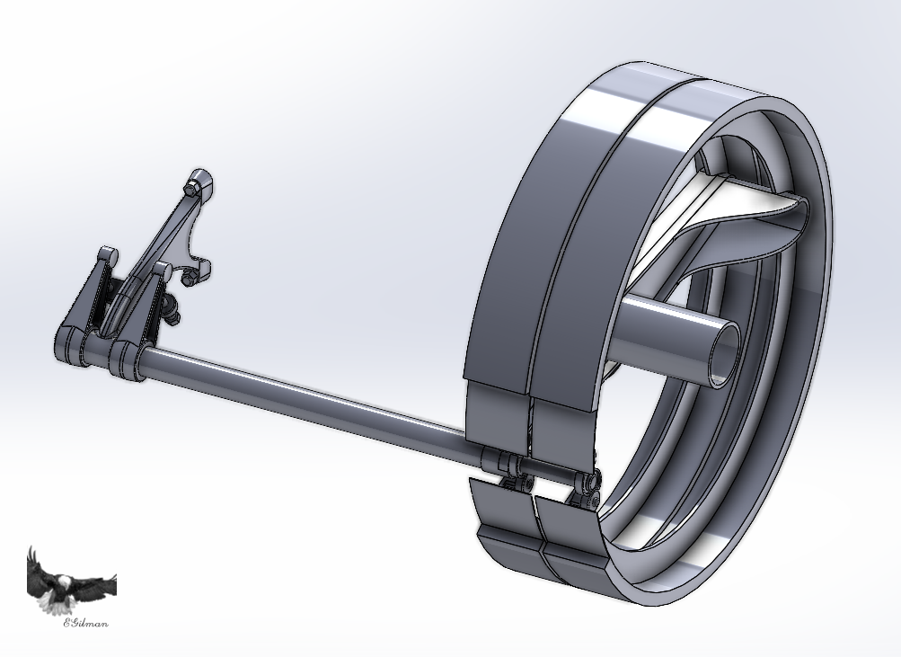
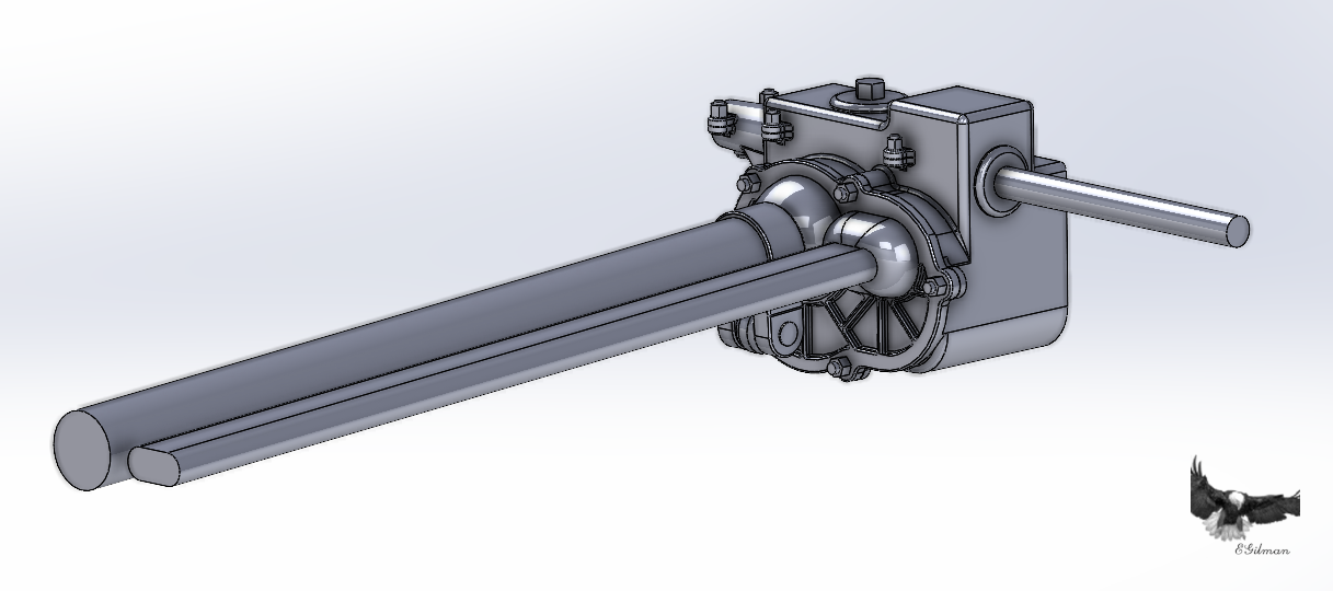
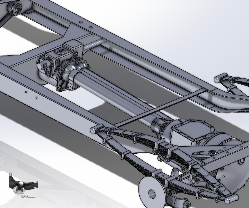
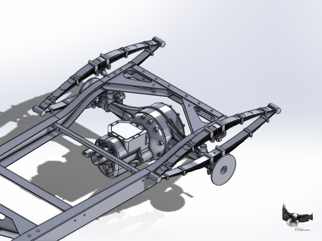
Ok Thrust Bearing and Driveshaft Tube... Now on the car the swivel part, (the ball shaped sections) had a black oilskin cover that pretty much obscures the retainer plate and most of the backside details underneath... There was just enough exposed on the current car to give me a pretty good idea of what is underneath... It's pretty straightforward but as far as the reinforcing ribs on the retainer plate, they are pretty much what my engineering background thinks they should be, it is how I would have designed it.. The retainer plate is kinda lite construction as it is only meant to keep the tubes in place... Here is what she looks like with the Tranny and Rear End... Closeup in the frame... The real change is the clamp on collar around the driveshaft tube, it takes the truss rod in the center and the diagonal braces on the outside which slip over a pin that goes through from one side to the other being pinned in place making the complete driveline package a simple bolt in part... It slips into the thrust bushing, bolted to the springs and then the collar retainer is bolted in place... Most of the assembly of the driveline sans engine takes place on the bench... Here is the overall... The intermediate brake shaft crossmember is turned off so you can see the installation of the collar better... Gonna take a day or two, then it's on to the Truss Rods and Diagonal Braces... From there probably on to the Brakes & Rear Wheels... Gradually getting back to where I was before... Onwards!!!
-
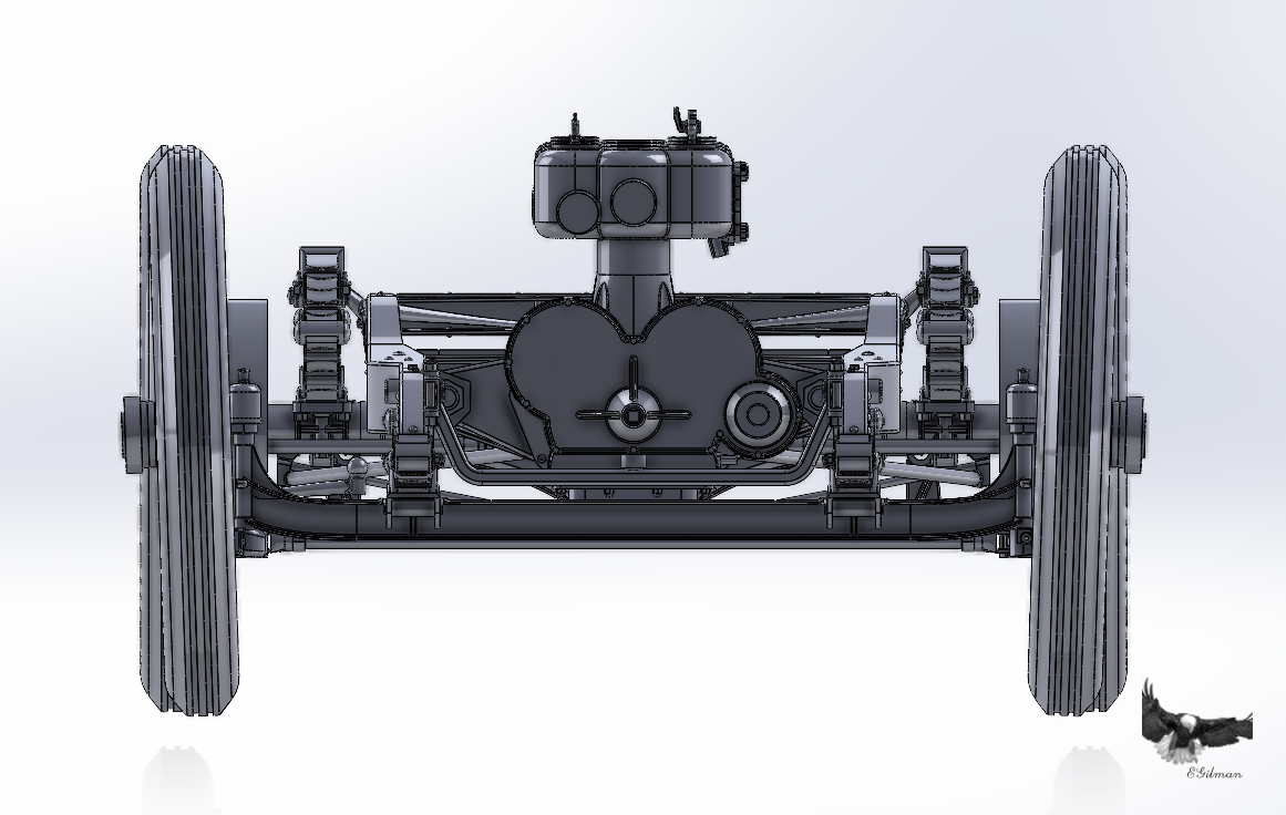
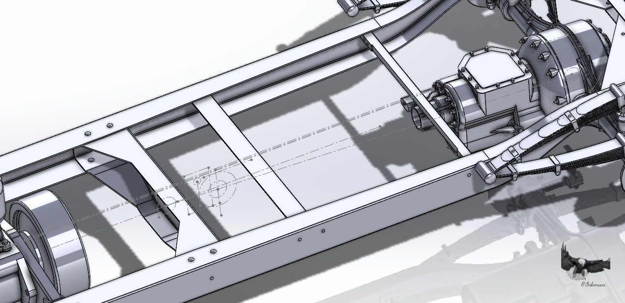
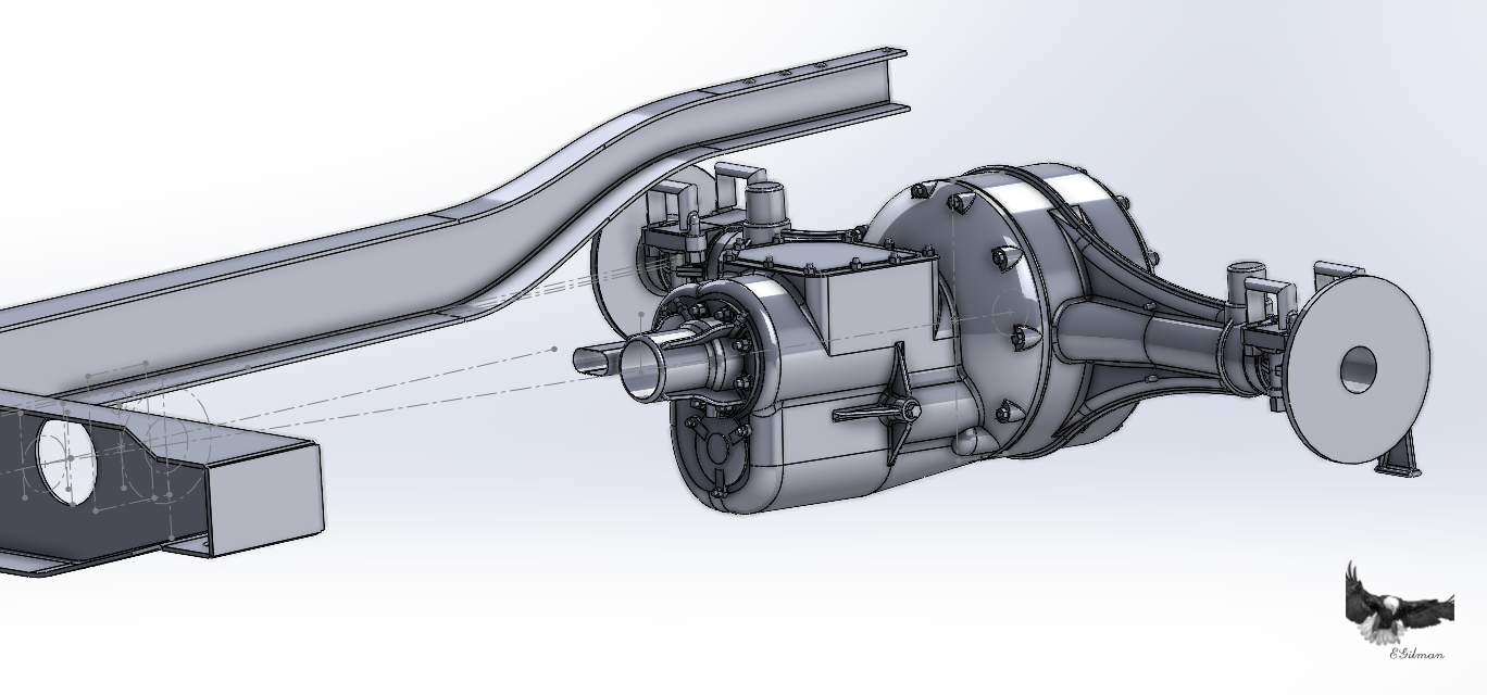
Well it's been an interesting few days.... It's time for another update.... I know in my last posting I was going to be working on the thrust structure... To do that, I have to get the Differential Housing, Transmission, Driveline Thrust Tube and the Thrust collar to line up properly... So what I do it create a sketch of the layout where each part can be recognized for what it is as well as it's position in the car overall and relative to each other... This is that sketch... Trust me it's all there... (I know a bit skimpy on the lines but what I need to know is present), And indexed to the cars model origin point, so what ever drawing I put this sketch in it will always be in the same model space just by dropping it on the origin point... But when I started adding parts, I found out that they weren't lining up very well... You can clearly see when the layout sketch is shown inside the car, the transmission is way too high... Too much angle for the Differential Housing which drives the Tranny height as well as angle.... I know when looking at the car it looks like it sits fairly lever, and it essentially does... The engineering of it is a bit different... She carries a 1.23 to 1.36 degree forward lean when sitting on all four tires... and the Axle drop angle is only about 3 degrees more or less, so these are such shallow angles that they won't show up in perspective laden photographs... As a result I've spent the last few days redrawing the Differential Housing and Transmission... this is what I've come up with.... You can now clearly see that the Driveline drop angle line runs right down the middle if the Thrust tube.... Just the way it should.... Now I won't bore you with the details of the re-engineering of these things... the Differential Housing was a piece of cake compared to the Tranny... And I'm done with the Tranny, I'm happy to say that I believe it is now approximately 98% accurate... Thanks to the many images I have access to... There is it.... Looking good now, it does match the pics very closely.... Phew I'm tired... Anyway, here is an overall shot, I'm going to get some sleep.... Enjoy... Will start on the thrust bearing when I wake.... (it may take a while) {chuckle} Onwards!!!
-
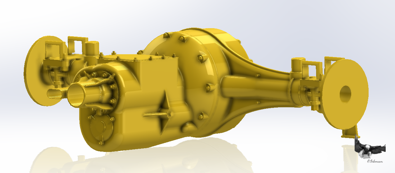
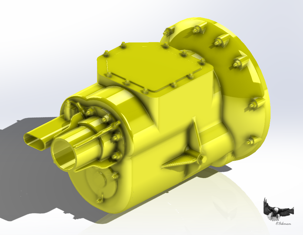
Well four days of working on this, I think I'm calling it done or at least done till something needs adjusting to fit other parts.... I painted it yellow for a beauty shot.... And mounted to the axle/differential... The car was all yellow, with black painted trim but only on the outside surfaces.... Anyway, the Tranny in it's position... And the overall shot, I know too far away to see the differences but I assure you they are there... I'm figuring that it is 95% accurate to what was on the car.... Anyway on to the thrust bushing.... Onwards....
-
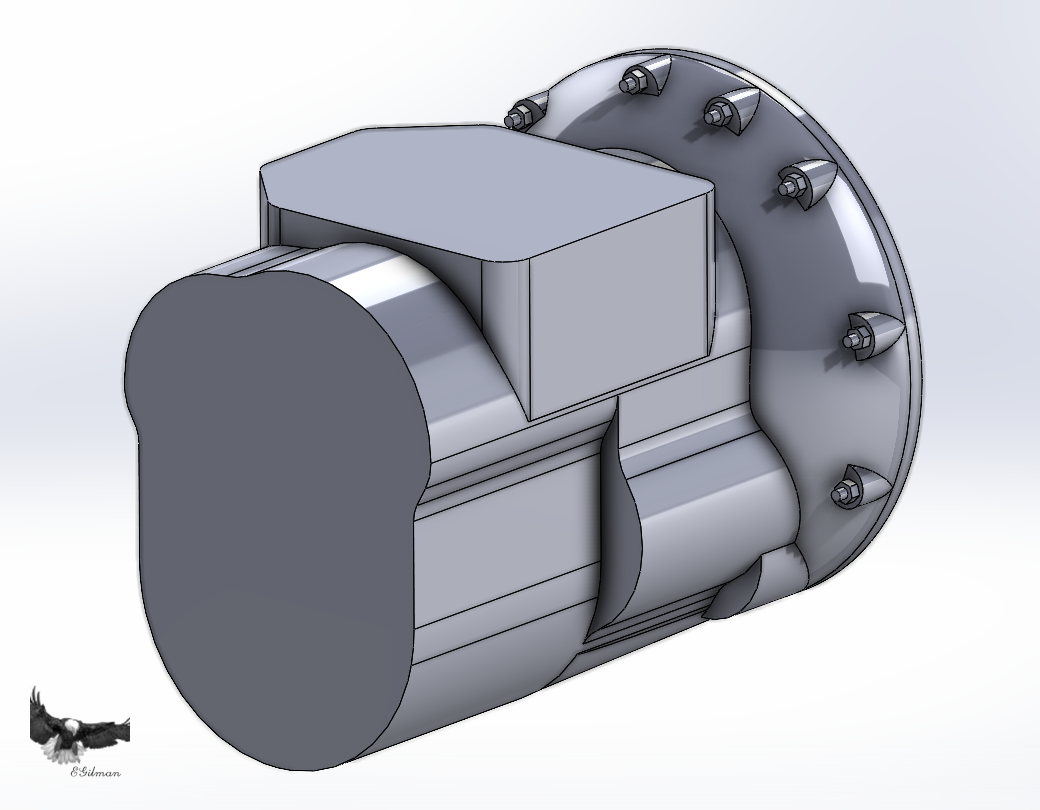
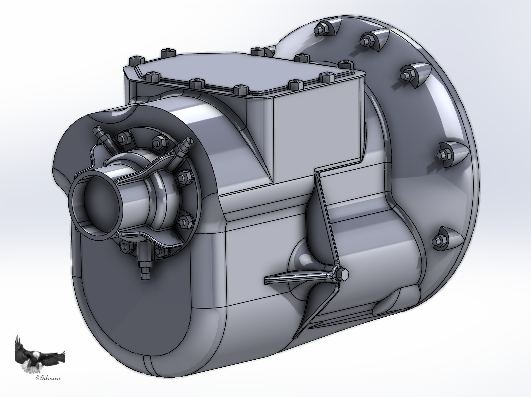
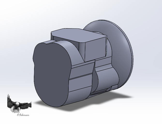
Another short update.... The vagaries of engineering... {chuckle} I ran into a problem with the transmission, parts that I now have info for wouldn't fit on the design the way it was configured.... And I had reached the point in detailing where I couldn't just back it out, and rework it... This is where I finally had to stop and reconsider the design... And what it should look like in real life... Yeah there are issues... So, I started the reconstruction.... This is what was.... This is now.... The differences are subtle, but they make all the difference in the finished model... Everything in the pics has to fit on the model.... This redesign should allow me an easier, more accurate path to the finished transmission.... Restarting the detailing process as we speak.... Onwards.....