kennb
-
Posts
1,056 -
Joined
-
Last visited
Content Type
Profiles
Forums
Events
Gallery
Everything posted by kennb
-
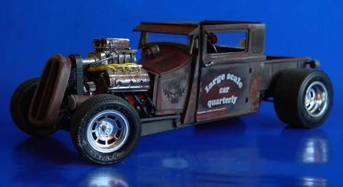
getting to start to look like a hot rod. Will be going to paint shop in the morning. KennB
-
Afew more photos showoing a little progress. The body is ready for applying the beading. I have a fire wall overlay to do with some detailing. I think I am ready to paint the motor block and apply the chromed parts. Wheels are being glued up and will be up tomorrow sometime. KennB
-
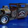
I have been working up some motors for another thread and have this Blown Hemi I have been building up. Got the things back from chrome shop and was looking for a place to put it. I needed to finish motor mounts before the block can be sent to the paint shop. It will have electronic ignition and partially wired and detailed. I have been toying with a 1932 Chevy 5 window coupe for it. I built this body up this morning, so now my hemi has a new home. The body is not done yet and the custom frame still needs attention but would like to start showing the progress. Of course it is all scratch built. What else did you expect from me . I will get the rubber done tonight. I am having some fun with the frame on this one. I should have this done this week end. It is a quick build. KennB
-
Looks realy interesting for sure.Thanks for posting it. I have been seartching for a new project. Need something to use my blown hemi in. nice 32 chebby maybe. As for this project I have been slowly painting parts and got the refrigerators and stoves for both trailers painted and chromed. Still looking for the right floor coverings. KennB
-
I am using thrmal stting plastic .40 thick. I also have used .30. This is a different composition that the hobb plastics in as that it is easily shaped and will hold the shape. The hobby plastics are very stable and will retain the shape the come in, i.e. flat will return to flat overnight, it has a memory. The thermal plastics only are stable after being heated and then you can not change the shape. Thiner would probably shape better but to get a working thinkness you would have to have more layers, not all a bad thing ince the glue between the layers helps to stablize the shapes. I have not tryed thinner stock for the bodys. KennB
-
Building the motor: Tools required: Exacto knife, needle nose pliers, files, ruler, paper punch, and sandpaper. Building a credible motor for your cars is not as hard as any other part of the car. You probably already have made valve covers, headers and other odds and ends for a motor. Now we put all that together to make one from scratch. Mind you the ones I have done are not detailed to nuts and bolts but do give the impression of a highly detailed model. You can add the wiring and other fussy parts it you like to gain further credibility of something that is exceptionally detailed. I have put together a few examples of what can be accomplished in a relatively short time frame. Plan to spend about three to four hours for your first one. As you gain confidence they can take as little as an hour or so to put together depending how much you do to it. If you are adding the blowers it will take a little longer. All the components are easy to do and parts like the valve covers, oil pans, and blowers are built up from layered material to get the thickness needed. The main body is hollow and as the drawing and photos show built up with strips and the ends that are shapes as shown. The pulleys are made using the paper punch. It does cut very nice circle of about the correct size. All the holes are started with the tip of the exacto knife and finished with a small drill bit. I use my fingers to twist it through. The plastic rod is all 1/16” cut and shaped. All the heads are made from this. I bend it with the needle nose pliers. I have the sizes for the block ends shown on the drawing. This is the first thing you need to cut out. It is just as easy to cut enough for 2 motors at a time. Set one par aside and then build up one motor. When you get the sides and ends glued up set them aside to dry. You will need to file the some to make sure they are smooth. Next I build up the valve covers. The base is a single layer and the upper parts are three layers. The intake manifold is two to three layers, I have used both, and then they are filed to shape. I use the edge of a needle file for most of this. Be sure to have the distributor hole put in the correct location, front or rear. I also take time to set up the exhaust headers at this time, the basic ones are three layers filed and shaped with the files. The front and back layers are cut now and the block should be ready to smooth out and apply the panels to the front and rear. Add small bits on the lower block to give the impression of a lot of detail. You can use strips, small squares, and some rod sticking into the block in a few places. Drill some holes in the front and insert some 1/16” rod for the pulleys. Use some punches with holes in the center on the rods to indicate the pulleys. An alternator is made up of three punches glued together a small bit of rod in the front and a pulleys over the rod. I use a little bigger bit of rod for the idler pulley. You can get as detailed with this as you want. I just get some placed to give the impression of more detail than is really there, for most applications this is fine. Now it would be a good idea to paint all the separate parts prior to assembly. We will continue with the motors in the next installment. KennB
-
Additional photos are available on the photobucket page. There are over 220 photos there of the build. http://photobucket.com/T-Birdconcept We will be starting the engine on the next installment. KennB
-
The interior: Tools required: Exacto knife, ruler, files, and sandpaper. The interior box is made up of strips about 3/5” high. One is cut to the width and then rounded off at the top edge to match the inside of the hood. The rear curve is transferred from the frame. This does not have to be exact but enough so the frame will set inside the body and even with the bottom edge of the body. The floor is about 2 ¼” wide x 1 ¾” long. All dimensions are approximate and will vary according to the model. After they are glued up it is time to start the seats. I used telescoping tubes sliced for the seat attachment to the interior box so they can swivel. The bottom cushion is about 1/2” x 5/8” 3 layers glued together. The seat backs are about ¾” high x ½” wide 3 layers thick. The backs are tapered to the top and all the edges of both parts are rounded and smoothed off. I connected the two parts with 1/16” plastic rod, a small piece of plastic sheet can be used also. The dash is made of formed plastic to meet the way you want it. I included the center counsel into the dash. This is not required. I added side strips for fillers at the sides of the top of the box and sanded them to fit to the sides of the body. You can see this in the photos. The steering wheel is made up of a thin slice of 1.2” plastic tubing and a small cut design out of plastic for the center ring. The post is some 1/16” plastic rod glued to this center ring. The handles and arm rests are shaped from scraps of plastic, with 2 layers for the rests. The side panel designs are rounds plastic shapes cut out freehand. These you can design as you go using a paper side panel pattern to sketch them out first. continued I am hoping that this describes it well enough for you to make it up for your model.
-
You can make a simple frame for any of them. A simple ladder frame would sufice to get them on rubber. Depending on what is missing from the engines you could work with what you have and make things like valve covers or oil pans and starters. It just depends how involved with salvaging them you want to get, KennB
-
I will be posting the interior build later today but thought I would look forward to the engine build with a few photos. It is a decent representation of the motor I am using for this model and the details can be carried out further as with any motor. Reminder that this is a total scratch build with very limited hand tools. KennB
-
The big problem with the studebaker kit is that the station wagon used entirely different tooling. It is stubbier and taller so there are no common parts that can be used. The Starlight coupe was unique in the tooling.........lets see what transpires with this. Mat redo the sides so they have a better look to them. KennB
-
Like all my projects it is indeed scratch built. I use no commercial parts for anything I build. KennB
-
Tony, Then it is worth the effort. I know not everyone would want to tackle scratch building a compleate car but it is good to know that ideas and concepts put forth can be used in part for modeling kits. That is the whole idea. Some parts will be usefull to everyone hopefully. Thank you for following along and the comments. They too are helping me in what I am doing. KennB
-
Finishing the frame and wheels: Tools needed: Exacto knife, wood ruler, files and sandpaper. Granted that all the things I have been doing could be done a lot better if I used a machine shop and a ton of tools. I have some of that stuff but tend to use the very basic tools and not a lot of them. I tend to use three or four different files and the exacto’s. With that said we continue with the construction of the frame. Last time we just got the basics, now we will take and complete this part with the addition of the front suspension with operating steering and the rear end. The A frames that we cut out are marked for holes. I used a small diameter plastic tube 9 about 1/16” for the parts. You can see them in the pictures. The rear pumpkin is just a few pieces that have been heated and pressed into a short piece of 3/8” tubing. They are cut out and glued together with a hole pierced through for the Axel. 1/16 or so tubing. This is shown in the pictures. I added some scraps of plastic to the A frames to indicate more detail and used other scraps to indicate body mounts. You can further detail the brake lines and fuel lines and other details as you desire. Most of the details is shown in other builds so I will leave it as is for now. The wheels are made from ¼” wide strips 16” long that have both end sanded to paper thin. I use an old tape dispenser plastic cut to act as molds for the wheels. I feed the strips into the form and glue both sides and let stand. The hubs are a series of telescoping tubes that will fit over the axels when done. Only the outer most tube is raised since I will be adding hubcaps and the other detail of the rims will be covered. These are finished to about 3/8” thick and should slip into the wheels with a little filing. The pictures show the different stages of construction. This should complete the frame and have it ready for painting. Next I will start the interior. Remeber that additional photos can be seen on the album located at this link. http://photobucket.com/T-Birdconcept Thanks to all those that are following and those that comment. I am hoping that there are some things that each finds some use of KennB
-
Thank you for all the comments and suggestions. Tyere has been a few the see why I am not pleased with how it is turning out, I may just set it aside for now and redo the partsw that bother me. KennB
-
maybe it will look better with a roof and windows.
-
Oh.....1954 Studebaker Wagon
-
KennB
-
Setting up a frame: Tools required: Exacto knife, pencil, ruler, files and sandpaper. In setting up the frame when you have no information you need to rely on knowledge from previous builds or research as to common framing for the era. There are also a lot of other cars to lean on for information. For this car I chose a traditional framing system since it is not complicated. It is typical ladder design with the inner side rails. If this car would have been built it most likely would have had the side rails to the outside of the body, hence the step down design. This creates a lot of problems building a frame because there are a lot of bends and curves, like in the Hudson Italia frame. For this example I could have used that same design but opted for the simpler frame. I started by using a side elevation and laying out the suggested frame design. (See the drawing above). From there I laid out the top and side views with the cross member locations to get the set up. Other framing will be added later but we do not need to develop a drawing of those since it is cut and fit. Cutting the parts is an easy process of gutting one piece and gluing it down on the plastic and tracing around it a few times so you have 3 layers. This is done two times. I don’t glue the front “forks” at this time but rather wait until I get the frame formed and then glue and hold in place until the glue is set.(usually about 30 seconds). The drawings for this car show the fork bending design. The reasons for this is to clear the front wheels and provide turning space. The cross members are built up in four layers in a long strip, sanded and finished before cutting to length. The formed pieces are carefully bent out of one layer. To hold everything together you can use metal weights, tape, or some type of jig. (The one I designed and posted works fairly well). The whole idea is that you need to have the rails square and even to place the cross members and “X” framing. To be continued in next section. KennB
-
Adding the filler as needed. Try not to overdo things since all you end up doing is sanding more. You can add more filler as needed easier than having to remove globs of filler. Once you get to the shapes and finish you feel is right it is time to prime. The first coats should fill sanding marks and "small imperfections". But don't rely on the primer to fix poor work. I use 99 cent wal mart cheapie primer and have had very good results from it. Now set the body aside and let the primer set up for a few days. Even if it feels dry to the touch it will take a day at least to cure, the longer you leave it at this point the better. We will start the frame next time. Thanks for looking and all the comments. I do hope that there are a few attempting to follow along with the build. Please keep up with the questions. It lets me know the parts that I forget to show. Sometimes one is so close to the project they don't show a part thinking it is to easy to show. I have almost 150 pictures in photobucket on this build alone. You can access them through this link.: http://photobucket.com/T-Birdconcept KennB
-
The door lines are scribed useing a pattern and the back side of the blade on the exacto knife. This is the pattern scribing the interior. The outside is done the same way. The red car was scribed using the zona saw and the wood ruler as a guide. I like using the patterns better since it is used on both sides and therefore they will be exactly the same. KennB
-
Sanding the form Tools needed: 150 grit sandpaper. 600 wet or dry sandpaper, needle files, and a wood ruler. Now the easy part starts, sanding, sanding, and more sanding. For the broad areas I use a wood ruler with sandpaper wrapped around one end. I work the long areas gradually rounding the shapes and working the raw plastic to the desired shape. I don’t use any filler at this point but keep working the shape with sandpaper. I use small bits with my fingers and sandpaper for smaller areas and the inside corners. For the tiny areas I use the needle files and slowly work the shape out. This is something you want to go slowly with. You can always take material off but it is harder to add material. The idea is to use as little filler as possible and only when it is close to the final shape. The second body I did I only used filler on the front and a little around the taillights. The redo I used more filler and the inside is not as neat as it should be. It is possible to have the inside looking as good as the outside if you work carefully and take your time. I am just learning this as you are as I build more cars. The Hudson is just my second car and I am going back and reworking some areas of that one with what I learning on these. Do not be afraid to go back and redo some parts that you are not happy with. The second body was doing great but ZI never liked the way the roofline was looking. It always looked too high at the rear. The other day I cut out 1/8” of the rear pillar and re-glued it. It now fits a lot better with the overall look of things. The other point is never be afraid to toss out a body that is not coming together. You can fight with it to the finish and not be pleased with it or you can just start over and things will work out better the second time through. When you feel the body is ready, start with the 600 w/d and sand before the first coat of primer. Add filler as needed at this stage but be sparing with it. Thin coats dry better than big globs and sand easier. Use bits of plastic to apply thin layers or the finger to get into the small places. Right now I am using white squadron and it has been doing ok for me, it dry’s relatively fast and sands smooth.
-
-
Front end Tools needed are the same as before. We are going to need a ¼” tube for the lights. A pen barrel would do okay too since they are about the same size. For the grill they are generally oval or some variation of that. For this car I have an oval with two variations. One with lights in the oval and one with lights outside the oval. The shell is 1/8” strips shaped as desired. With small scrapes of plastic fill in around where you are going to have the grill and lights. This is a cut and fit operation and may take two or three tries to get it right. Then with 3/8” piece about 3” long create the lower valance. Look at the pictures to get further information. I have two ideas shown. The grill opening works best if it is open. I have tried them filled in and they just don’t work out good. The model at the beginning of the tutorial is filled in. I have since redone that car. It is in the photos in this segment. This is a lot cleaner build than the red one. I tore the first bird apart, front and rear and redid both parts because they were terrible. I a posted more pictures of the rear to give some more ideas in he next post.. KennB If you need furthe details or information let me know.
-
Finally got some wheels for this thing. Now that it is on rubber. I dont like the windshield and thinking I should try another attack on it. wonder what a bubble top would look like on it. I do need to cut it down to about half of what it is. It looks way too out of proportion to the rest of the car. KennB