tyrone Posted March 23, 2012 Posted March 23, 2012 chassis work is looking great,,, keep those pics rolling,,, love these pro mods...
jmpsebring Posted March 23, 2012 Author Posted March 23, 2012 In-process of the cage section. I have only tacked in this side at three places. I plan on removing it to re-gain access to the middle.
jmpsebring Posted March 23, 2012 Author Posted March 23, 2012 I get to play some..... Double checking
Mooneyzs Posted March 23, 2012 Posted March 23, 2012 Jack... Your progress is just awesome! It is coming together quite fast. I love the pic of it mocked up with the wheels and engine. It looks awesome. Nice work man!
Romell R Posted March 23, 2012 Posted March 23, 2012 Hey Jack what engine block and vavle covers are you using?
MicroNitro Posted March 23, 2012 Posted March 23, 2012 That intake is awesome did you make it? Your caps and hubs will go out this morning.
jmpsebring Posted March 23, 2012 Author Posted March 23, 2012 Hey Jack what engine block and vavle covers are you using? The engine block and heads are right out of the Funny car model. I added to the width, about an 1/18th and wrapped the heads with some thin strips making them smoother and slightly bigger. It also made them the same size as the valve covers. Even the valve covers are stock. I took the Hemi covers and ground down the tops, filled the center with APOXIE putty and sanded them. They are 90% done.
eviltwincustoms Posted March 23, 2012 Posted March 23, 2012 Day two and more bars Looking good Jack! Since I know nothing about brass and solder, I have a very novice question for you. When you solder each joint are you putting some sort of heat sink close by? Or by using the flux and something like "Tix" solder creating the sweat joint fast enough the other joints don't come loose? The other thing, you may have noticed and already taken note. If that is the clutch can you will be using, you may want to go back and raise that top bar a bit. You don't want to sandwich the Clutch Can between the chassis and our block mid plate. It should be in between the uprights and the top and bottom bars, and then you should be good to go! I really like how you made the front clip slip in and out of the rest of your frame. My understanding based on what Dave has mentioned, the front clip tubing should be smaller anyway. So you can actually down size from the firewall going forward!
jmpsebring Posted March 23, 2012 Author Posted March 23, 2012 Before and after. Just trying to make a more modern engine. Plus I'm trying to lock in all of the drive's shapes and locations so I can check for clearance.
jmpsebring Posted March 23, 2012 Author Posted March 23, 2012 Looking good Jack! Since I know nothing about brass and solder, I have a very novice question for you. When you solder each joint are you putting some sort of heat sink close by? Or by using the flux and something like "Tix" solder creating the sweat joint fast enough the other joints don't come loose? The other thing, you may have noticed and already taken note. If that is the clutch can you will be using, you may want to go back and raise that top bar a bit. You don't want to sandwich the Clutch Can between the chassis and our block mid plate. It should be in between the uprights and the top and bottom bars, and then you should be good to go! I really like how you made the front clip slip in and out of the rest of your frame. My understanding based on what Dave has mentioned, the front clip tubing should be smaller anyway. So you can actually down size from the firewall going forward! It's tricky at times to solder things together. I'm using radio shack 60/40 resincore solder. I'm also using an acid flux. That's the magic juice IMHO. So far I have not used any heat sink. The iron is so hot and the flux allows me to heat the joint and move away in about a second. It didn't even melt the plastic a-pillar with the joint sitting on it!. Plus, I'm not always soldering a joint just once. Tack in point A holding the part in place with my fingers. Tack in point B, inspect, adjust if needed, then go back and re-do point A with acid and solder on the tip already. This time I concentrate on looks. EVERY time I wipe the tip keeping everything as clean as possible. I will cheat as needed. The Lenco rails might not be soldered or even made from brass. I might JB weld a joint if I feel it's impossible to solder some place that will cause problems. Still, overall I think it's far faster and stronger to do this part in brass. Sometimes I'm a 1/32nd away from even touching the joint having trimmed the rod too short...the solder simply fills the area. Romell, chose to push himself to make everthing from scratch. I'm way to lazy for that. I kit bash and compromise everywhere I can. Then there's Dave who works for perfection. I'm not nearly that dedicated. I'm not understanding what you mean. Not the raising the bar part...more why I should raise the bar. Are you saying that the clutch housing should be moved forward or backwards? EXP: engine block,Plate, firewall panel,Tubes, with the clutch housing floating between the tubes? I do know that engine height up and down can not be adjusted now and I worry about sump clearance. I also worry about rear tire body width. I would do some things differently. Having said that, I will make another post.
Dragracer Posted March 23, 2012 Posted March 23, 2012 I don't know for sure,but the valve covers look like they are on upside down. The chassis is looking good. Keep it up!, like this build!
jmpsebring Posted March 23, 2012 Author Posted March 23, 2012 This is more about a build ethic than anything else. Everything I build has a final look I'm going for. Anything outside that look is not as important. It's a balance of time and payoff. This will have a permanent display case and the car will be up on Pro-Jacks, with doors and nose removed. Look at Romell's last side view shots...they are amazing!s The Jacks will have hidden runners running through the base and attached from underneath. It has to hold a wide heavy chassis forever! I might even solder the frame to the Jacks. I didn't spend all this money on hubs and removable wheels and printed rear ends to hide them! Plus I like all cars in the pits more than on the track. I will never put the nose in place, never put the doors on so it's not important that everything fits perfectly and the door hinges make the right arc. That will save hundreds of hours and a huge amount of stress. The time saved will allow me to perhaps build a kool jig that the doors are hanging on while in the pits. I might build only the scene-facing side of the transporter, creating a background wall. That would be really kool because while painting the body, I could also be painting the same type of scheme on the transporter. That means I can "kinda build" a transporter without really building a huge 1/16th truck/trailer...requiring a huge $$$ case and another year of my life. My next Promod will be the Willy's body curbside with only the fitted, working nosed removed. That will save huge amounts of money/time and I will concentrate on a kool motor and paint. I offer this not as an excuse or not to say others are wrong. If you want pistons inside your motor..no problem. Hell, I enjoyed looking at the clyinder walls of Bart's engine block! Go For it!! What's important to you? No matter how detailed it is...someone will ask me if it runs and somebody will tell me how they like to burn their models up in a big crash.... . Others will say.. that's nice and walk away thinking what a waste of time. He could have flipped a house and made money.... We've all been there so enjoy the build..if you get any ideas then great! The cynergy of us building together, raises the joy for all and keeps us all going.
jmpsebring Posted March 23, 2012 Author Posted March 23, 2012 I don't know for sure,but the valve covers look like they are on upside down. The chassis is looking good. Keep it up!, like this build! I'll look into that! Where did I put those kit instructions? Is that based on the angled corners?
jmpsebring Posted March 23, 2012 Author Posted March 23, 2012 (edited) here is the ref I'm using as a guide. Not building this...just something like this. If someone wants to mill me a set of those covers...... . Edited March 23, 2012 by jmpsebring
Dragracer Posted March 23, 2012 Posted March 23, 2012 I am going by the angles on the covers,the angle on the bottom left I believe should be on the upper right, and the little bit of the head that is showing in the bottom right corner should be covered by the cover.
W-409 Posted March 23, 2012 Posted March 23, 2012 Amazing build, I can see that we have one very talented builder here building this Duster. Frame looks very good too, but especially I like that engine. It looks Super Nice to me. I'll be watching this one very closely.
eviltwincustoms Posted March 23, 2012 Posted March 23, 2012 I'm not understanding what you mean. Not the raising the bar part...more why I should raise the bar. Are you saying that the clutch housing should be moved forward or backwards? EXP: engine block,Plate, firewall panel,Tubes, with the clutch housing floating between the tubes? I do know that engine height up and down can not be adjusted now and I worry about sump clearance. I also worry about rear tire body width. I would do some things differently. Having said that, I will make another post. NO problem, it is a bit difficult to explain. So where your Clutch CAN "Bell Housing" is sitting. You see that you have a chassis bar at the top and bottom of the CAN and on each side to form the firewall right? So the one on each side you can see it just clears the CAN for the proper width. However at the top and bottom, your Can "Lip" touches the top and bottom bars. On a real 1:1 this could never happen, because you have to be able to mount the "Bell Housing" to the Mid Plate that mounts to the firewall. That Mid plate mounts to the back of the Engine block first then your Multi disc clutch mounts to the mid plate then the Mid Plate should mount up tight against the chassis firewall. The way it is currently, you would be mounting the bell housing up against the chassis frame section and your Mid plate would stick out further away from the frame. I hope that helps.
Romell R Posted March 24, 2012 Posted March 24, 2012 NO problem, it is a bit difficult to explain. So where your Clutch CAN "Bell Housing" is sitting. You see that you have a chassis bar at the top and bottom of the CAN and on each side to form the firewall right? So the one on each side you can see it just clears the CAN for the proper width. However at the top and bottom, your Can "Lip" touches the top and bottom bars. On a real 1:1 this could never happen, because you have to be able to mount the "Bell Housing" to the Mid Plate that mounts to the firewall. That Mid plate mounts to the back of the Engine block first then your Multi disc clutch mounts to the mid plate then the Mid Plate should mount up tight against the chassis firewall. The way it is currently, you would be mounting the bell housing up against the chassis frame section and your Mid plate would stick out further away from the frame. I hope that helps. Bart if you look close the lip of his can is sitting on top of the bottom barthe edge of the lip has been flattened on all four sides, which means the can is sitting perfectly between all four bars. there are no adjustments to be made. the mounting plated will be snug against the chassis ,I suggest you look at the pictures again.
eviltwincustoms Posted March 24, 2012 Posted March 24, 2012 Bart if you look close the lip of his can is sitting on top of the bottom barthe edge of the lip has been flattened on all four sides, which means the can is sitting perfectly between all four bars. there are no adjustments to be made. the mounting plated will be snug against the chassis ,I suggest you look at the pictures again. Hey Thanks Rom, if the Bell Housing is Flat on the top and bottom then you are correct Jack is good to go! I guess I can say my eyes are not adjusting the the picture because, to me..... the CAN doesn't look like it has flat spots on the top and bottom. My mistake, maybe I should by me a pair of those magnifying glasses on the hood like Chris has and that will help me out.
Mike Kucaba Posted March 24, 2012 Posted March 24, 2012 I like the way you built the chassis inside out. I wonder if a plastic safe foam,or even plaster could be poured into what ever body you were going to use and get a buck of the inside,then cut and bend the rod/tubes around the buck.
Romell R Posted March 24, 2012 Posted March 24, 2012 I like the way you built the chassis inside out. I wonder if a plastic safe foam,or even plaster could be poured into what ever body you were going to use and get a buck of the inside,then cut and bend the rod/tubes around the buck. If you did that the chassis wouldnt fit the body anymore because you would actually be building outside the space meant for it.
jmpsebring Posted March 24, 2012 Author Posted March 24, 2012 If you did that the chassis wouldnt fit the body anymore because you would actually be building outside the space meant for it. I did build most of a Paris/Dakar racing/service truck once. Crazy Trucks! Youtube has some great vids. I placed thin strip all over the body with white glue. Then built a frame over the strips. Removed the strips and had a perfect little exo-skeleton frame wrapped around the cab. It's waiting for the last step......15 years ago!
jmpsebring Posted March 24, 2012 Author Posted March 24, 2012 Hey Thanks Rom, if the Bell Housing is Flat on the top and bottom then you are correct Jack is good to go! I guess I can say my eyes are not adjusting the the picture because, to me..... the CAN doesn't look like it has flat spots on the top and bottom. My mistake, maybe I should by me a pair of those magnifying glasses on the hood like Chris has and that will help me out. What you all fail to understand...is that I put that part there simply to admire my own work Good thing it stuck there! I spend way too much time stacking/sticking parts after every step..I can't help it So the midplate has the housing mounted to it. It must go through a hole cut big enough to allow a clucth housing's O.Dia. to pass through. Plus the midplate can't act as both a midplate and firewall. So the housing must be moved forward enough to match the thickness of the firewall. Plus there is no space bewteen the plate/firewall and housing. They form a solid sandwich...? Or is the fire wall flush with the tubing and welded in place forever? Also is the material around the whole firewall aluminum...or steel or composite? With the sunken panels I see it appears to be aluminum? Still another question. Are removable floor panels on the pass/NOS side removed from the bottom or top? I would think they must mount from the top with the Dzus tabs under them to ensure they can't blow through from wind. Is there a 2nd floor pan covering the whole floor area mounted on the bottom? Are welded steel panels from seat to pedals required around the driver's floor area ?
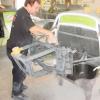
jmpsebring Posted March 24, 2012 Author Posted March 24, 2012 various strips of plastic to start forming a bumper
jmpsebring Posted March 24, 2012 Author Posted March 24, 2012 Time to dig out TOO much stuff! BTW, one of my fave project bases, are from the 'as-is' section at Ikea. Various shelves from various units. Perfectly finished, completely square and they are usuallly $.50-$1.50.
Recommended Posts
Create an account or sign in to comment
You need to be a member in order to leave a comment
Create an account
Sign up for a new account in our community. It's easy!
Register a new accountSign in
Already have an account? Sign in here.
Sign In Now