fractalign Posted August 10, 2014 Author Posted August 10, 2014 In case you can't tell its the hood or as we call them over here the bonnet. Its a very complex structure and i spent at least a couple of hours measuring it rescaling the measurements and transferring them onto this piece of sheet styrene. This won't be the the actual bonnet, rather it will act as a buck of sorts, not to shape the curves but rather to measure the parts against. The bonnet has a curve that runs side to side and front to back and the centre spine rises slightly as well. Its quite a complex structure and to tackle this one I will be building it in Four stages. First and second stage will be the centre spine which will consist of the two halves. From here I will add the two flatter sides. I will be cutting the pieces to exactly the same dimensions as the ones on this buck. The only difference will be that I will be shaping the pieces longitudinally to get the correct curve. For the width curve I will bevel the edges on the sides until I get the desired angle. Next task will be to begin cutting the pieces and getting them ready for assembly.
1 bad55 stan Posted August 10, 2014 Posted August 10, 2014 Good stuff Robert,I could never build something from scratch like you are doing..Keep it up...
Daniel Lynch Posted August 11, 2014 Posted August 11, 2014 Wow! Simply terrific job! Do you work for model company?
fractalign Posted August 11, 2014 Author Posted August 11, 2014 Hey Guys. I put the bonnet together today. It was one of the easiest parts of the build and one of the quickest too. I still need to do the underside and that will be anything but easy or quick but finishing the exterior of the bonnet gave me a platform to work from in relation to getting the rest of the body in alignment. The first task was to cut the pieces and check them against the template.
fractalign Posted August 11, 2014 Author Posted August 11, 2014 (edited) With that done, the two pieces were curved and glued together to make the spine. Edited August 11, 2014 by fractalign
Pim Posted August 11, 2014 Posted August 11, 2014 looks cool what did you use to cut the sheet styrene
fractalign Posted August 11, 2014 Author Posted August 11, 2014 (edited) With the spine done the sides were next. Edited August 11, 2014 by fractalign
fractalign Posted August 11, 2014 Author Posted August 11, 2014 Here are the three sections before they were glued together.
fractalign Posted August 11, 2014 Author Posted August 11, 2014 (edited) And here is how the bonnet looked afterwards. Edited August 11, 2014 by fractalign
fractalign Posted August 11, 2014 Author Posted August 11, 2014 I made sure too keep the curve with the sides and the spine in alignment.
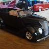
fractalign Posted August 11, 2014 Author Posted August 11, 2014 Here is how it looks with the body. With the bonnet finished I was able to gauge where the cowl will sit and where there nosecone will sit as well.
fractalign Posted August 11, 2014 Author Posted August 11, 2014 (edited) Because the contruction of the bonnet was so quick I had time to get something else underway. Edited August 11, 2014 by fractalign
fractalign Posted August 11, 2014 Author Posted August 11, 2014 I had time to go out and get some more measurements, this time the width of the floor pan from rocker flange to rocker flange. With the measurement I was able to construct a jig. While many jigs are external units often centred around a box, I realised that would not work with my project. An internal jig was constructed so that I would heave ready access to the outer body at all times. Slats were cut into the top. These slats will allow a templates to be added where needed. This one is slotted in where the firewall will sit.
fractalign Posted August 11, 2014 Author Posted August 11, 2014 To keep the body sides from falling over there will be a number of contour templates added to the outside. These will attach to the underside the same way the internal templates attach to the top with slats to be cut.
fractalign Posted August 11, 2014 Author Posted August 11, 2014 The next task will be to finish the jig and start constructing the floor firewall and engine bay. Here is an image of what the floor looks like. I will be getting as many measurements from it as I can over the next few days, along with the engine bay.
1 bad55 stan Posted August 11, 2014 Posted August 11, 2014 You have made some good progress,carn't wait to see more...
Byron5150 Posted August 12, 2014 Posted August 12, 2014 Dang looking good!! I'm real mechanically inclined and patient. But I don't think I'd have the patient of building this from scratch! Great job on the hood so far
fractalign Posted August 12, 2014 Author Posted August 12, 2014 Thanks for the feedback guys as far as having the skill mine are average at best. The trick with any scratch build is good reference material, accurate measurements and a good eye. If you have these you will be surprised at what you can put together. Speaking of putting things together, I did not get anytime to work on the build today but I did go down to the garage to get some more measurements. This time of the floor, this will be one of the most challenging parts of the build, but with the new jig it will be made a bit easier. Hopefully be this time tomorrow night I should be back on track with the build.
microwheel Posted August 12, 2014 Posted August 12, 2014 Hi Robert, outstanding scratch building skills my friend. I look forward to more.
fractalign Posted August 13, 2014 Author Posted August 13, 2014 (edited) Hey Guys. I got started on the floor pan today. Yet another challenging part of the build, come to think of it there seem to be no shortage of challenging parts in this build. There were two options for doing this, the first would be find a floor from another kit and modify it to look this one or start a fresh from scratch. Since I don't have any other kits from this era the latter was my only option. Measurements were taken of the front half of the floor, that is the part of the floor up to and including the cross member. If you look closely you will notice how the floor is not flat but actually dips down in the centre, getting this part right will be the hardest part of doing this floor. Edited August 13, 2014 by fractalign
fractalign Posted August 13, 2014 Author Posted August 13, 2014 (edited) Here is what I started with. The transmission tunnel was the end of a funnel that was sliced lengthways. Edited August 13, 2014 by fractalign
fractalign Posted August 13, 2014 Author Posted August 13, 2014 After tracing around the transmission tunnel I attached the crossmember.
fractalign Posted August 13, 2014 Author Posted August 13, 2014 With that done I marked out the area fro removal.
Recommended Posts
Create an account or sign in to comment
You need to be a member in order to leave a comment
Create an account
Sign up for a new account in our community. It's easy!
Register a new accountSign in
Already have an account? Sign in here.
Sign In Now