Skypower Posted February 7, 2014 Share Posted February 7, 2014 Thank you John, that's one of the things I have been scared of messing up. I don't want to ruin a $30 motor and I haven't had any experience with resin stuff yet. Quote Link to comment Share on other sites More sharing options...
jaydar Posted February 7, 2014 Share Posted February 7, 2014 That is a great technique tip. Although I have worked with resin pieces for years as a plane builder, i never marked the piece, just eye balled it. Thanks, Joe. Quote Link to comment Share on other sites More sharing options...
FASTBACK340 Posted February 8, 2014 Author Share Posted February 8, 2014 OK, quick update: When it comes to assembling anything, measure, align, inspect, and repeat BEFORE you super-glue it together. Yours truly just realized he roached the first block. Fortunately I had a second 340 6Bbl. kit to rob the block from, but now I skipped an important step after assembly when it comes to resin: cleaning the mold release off the pieces BEFORE applying primer/paint. My engine is going for a swim in Lake Castrol tonight. Clean your resin in Westleys Bleach White. The resin was greasier than a Pork chop, beautifully detailed…. but loads of contamination. My bad… still doing stupid things. Feel like I never took a hiatus! Quote Link to comment Share on other sites More sharing options...
Mopar - D Posted February 8, 2014 Share Posted February 8, 2014 John To help from losing any of the small parts I down the drain I use a zip lock baggy with Westlys bleach and the parts I also use the bag to rinse off the Westleys bleach. Yea I learned the hard way keep up the the super detailing on your build. Quote Link to comment Share on other sites More sharing options...
1930fordpickup Posted February 8, 2014 Share Posted February 8, 2014 Yes John we are all human . That is a good looking engine. Quote Link to comment Share on other sites More sharing options...
Skypower Posted February 8, 2014 Share Posted February 8, 2014 More good info, Thanks John I would not have known that. Quote Link to comment Share on other sites More sharing options...
FASTBACK340 Posted February 8, 2014 Author Share Posted February 8, 2014 G`morning all. Been busy wasting the morning…. now it's time to go to work. As much as I'd love to watch the young Ladies ice skating on the Olypmics, I have a small block Mopar to address. I also have to spot-prime the chassis splice and post the final amendment to the splice strengthening. I removed all the manufacturer logo's and have modified the rear leaf springs & shackles. Some simple detail painting alone will make this pop nicely. I remember building the `69 version when it first came out and I still love it today. I'll be back later……. * Quote Link to comment Share on other sites More sharing options...
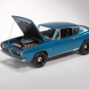
FASTBACK340 Posted February 8, 2014 Author Share Posted February 8, 2014 I need a new chair at my bench. My upper back is hurting….. I could have stuffed 2 pieces of plastic under the spring perches, but I decided it was just as easy to make shackles. I took a length of 3/32" brass strip & folded it over itself twice and drilled 2 sets of #78 holes. After trimming and filing I temporarily pinned it all together. Once I make a set of longer shocks from brass tube that will support the weight as these are thin…. but look pretty darn good. And as a teaser-shot, we painted the engine. Once it's dry we can start the assembly. I fab'ed up a set of sheet metal valve covers and I am making the breathers next. I might start painting some suspension/steering bits and let things dry and get back on the Pink `70. We're moving forward! Quote Link to comment Share on other sites More sharing options...
FASTBACK340 Posted February 8, 2014 Author Share Posted February 8, 2014 (edited) ** SORRY ** Double-post. Edited February 8, 2014 by FASTBACK340 Quote Link to comment Share on other sites More sharing options...
FASTBACK340 Posted February 9, 2014 Author Share Posted February 9, 2014 OK, here's that final tip on strengthening butt-joint panels. This trick I learned from the late Tony Delvecchio, president of the LIARS club until his passing. He was an incredible customizer that had an eye for what would work, and what wouldn't. This is how he held some of them together. Materials needed are 3/4 ounce fiberglass mat from the R/C dept. of a well stocked hobby store. A straight edge, a hard surface to cut on, scissors, toothpicks or a small steel paddle, Xacto w/ a fresh blade, and gap filling super glue. Cut it to a smaller size on a hard surface. The closer to the final size the better. If you trim it with scissors it will shred a bit and get sloppy. Once it's laid over the area that needs to be reinforced, you soak it with super glue. Smooth it out and work the glue into the matting. It will soak up the glue on it's own. Just push it down tight against the surface your strengthening. When it dries it is very stiff. It can be cut and sanded after it cures, but trimming now makes your life easier later. Now you have a fiberglass reinforced patch overlapping the two pieces. A piece of plastic was used also, but due to the shape the matting conforms better, creating a stronger patch. Plus it's very thin and won't interfere with other components. This works for top chops, frame sectioning, altering wheelbases. Anywhere you need to add strength to an assemble that may flex and crack. Great tip Tony. Thank you. Quote Link to comment Share on other sites More sharing options...
FASTBACK340 Posted February 9, 2014 Author Share Posted February 9, 2014 OK…. while I did spend some time at the bench this afternoon, it was a relaxed day as Amy went shopping and the dog decided to sleep instead of harassing me, that lovable mutt. Although I realized I have to invest in a new chair, I had fun. Aside from doing the fiberglassing, I also installed the cable brackets for the emergency brake cables and the rear brake line bracket, which went in after these pictures were uploaded. I also removed the cast-in gas tank straps and I made my own J hook brackets for the upcoming straps w/J hooks. Here I made the brackets by drilling two #70 holes in some thin brass strip and bending them 90 degrees. I then cut slots in the frame from the inside with a saw. Giving me nice, clean slots through the floorpan. Then I dropped the strip through the slots In the back I folded a piece of wider brass strip and made the slotted tip for the J hooks to grab, Separated the two pieces and dropped them through the floorpan. I'll make the wraps from thin stainless steel shim stock I have, the J hooks from wire. Simple mounts that need to be sturdy. I hate having thin pieces snap off after painting forcing either a re-paint or repair. These brass pieces are super glued in nice & solidly. Quote Link to comment Share on other sites More sharing options...
FASTBACK340 Posted February 10, 2014 Author Share Posted February 10, 2014 OK, today was spent fussing with little things, painting, and some fabricating. I installed the last bracket for the brake hose and added the side pieces for the tank support mounts. I still have to install the sump for the fuel tank (I keep forgetting!) and I have to make the sub-frame connectors and driveshaft loop. Here's todays results. I might go assemble and wire the engine later. Watching the Olympics with the Mrs. right now…. I have to find a small MILODON decal for the oil pan. The Lakewood scatter shield is a wheel back sanded and opened up for the clutch fork. The actual valve covers are welded aluminum sheet metal powder coated Alien Silver. I'll use Testor's German Silver on these scratch-built pieces. The holes are for the allen bolts on the 1:1. The aluminum radiator is buffed aluminum metalizer. Here you can see the mounting tabs for the e-brake cables on the frame railthe hydraulic hose mount for the rear axle. And here's a shot of the reinforced tank mount. A strap wraps around from up front and get's anchored to these plates with J hooks. This isn't hard, it's just tedious. A good supply of material is key. We might have more later, but that chair at my bench has to go….this week. Maybe tomorrow. I'll put it out in the trash TONIGHT….. Quote Link to comment Share on other sites More sharing options...
Mopar - D Posted February 10, 2014 Share Posted February 10, 2014 John nice progress I really like the level of detail your going to with this and thanks for sharing the fiberglass technique for reinforcements. I going to have to pick up some as I can see how this will work on some of my upcoming projects. Quote Link to comment Share on other sites More sharing options...
hgbben Posted February 10, 2014 Share Posted February 10, 2014 Looks amazing John Quote Link to comment Share on other sites More sharing options...
FASTBACK340 Posted February 10, 2014 Author Share Posted February 10, 2014 Thanks guys, I have more. Last two things for tonight are going to be the sub-frame connectors and the MSD distributor. The sub-frame connectors are just a pair of steel tubes connecting the rear uni-body sub-frame which holds the rear axle and suspension with the front sub-frame that holds then other end of business. Even stock, these old Mopars handle terribly. Add horsepower and hard launches and one day your doors won't open and the back glass *might* pop out….due to chassis flex. When I welded in mine just pulling off the lift and making a u turn in the street I felt a difference. I have the Competition Engineering units that drop down as opposed to the Mopar Performance pieces that are straight. And would have been easier to make. These are eye-ball bent and cut to fit using some 1/8" brass square tube. The distributor is nothing more than some Radio Shack wire wrap, aluminum tube, and plastic rod. I filed 9 notches in the edge of the tubing Then I routed the wires into the tube with the plastic rod stuffed down the center. A drop of super-glue holds it together Now the wires are routed to the notches. I'll find a small nail to use the head as the wire retainer on my MSD unit. I'll paint the upper half of the aluminum red to resemble the cap. That's it for tonight gang. G'nite! Quote Link to comment Share on other sites More sharing options...
Ramfins59 Posted February 10, 2014 Share Posted February 10, 2014 John this is looking great. You're blowing us all away with all of your fantastic detailing. Go man go...!!! Quote Link to comment Share on other sites More sharing options...
crazyrichard Posted February 10, 2014 Share Posted February 10, 2014 awsome stuff Quote Link to comment Share on other sites More sharing options...
FASTBACK340 Posted February 11, 2014 Author Share Posted February 11, 2014 Well I think I'm taking it easy tonight. I'm in the middle of swinging a CVT transmission out of a brand new JX-35 at work and my back is aching now…. and tomorrow I continue. And that chair in my hobby room is shot to hell…. Tomorrow night we go to the accountant and will stop at Staples on the way home. I got permission to get a new throne at the bench. For now, here's some shots of all the grubby details on the 1:1 Oddly, this is the only picture I have of the engine before it went in. That's my boy Cesar helping me drop the bullet in. The only person I'd let near the car with a wrench. Here you can see the Orange, aluminum, and gold. Here's the actual sub-frame connectors. This is the tank w/ sump for the fuel line Next two projects: Fuel pump, shield, filter, and lines And these monsters that I have absolutely no clue as to where I'm getting them from….. These are TTI polished ceramic coated step tube headers, the ONLY ones that will fit without dragging on the street. Here's my reference for current and immediate sub-projects on this build. Geeez, I'm tired just thinking about all the work I have to do yet…. Quote Link to comment Share on other sites More sharing options...
hvymtl Posted February 11, 2014 Share Posted February 11, 2014 Wow So Cool Michael Quote Link to comment Share on other sites More sharing options...
FASTBACK340 Posted February 11, 2014 Author Share Posted February 11, 2014 With the sump the line is pretty much level with the pump, plus the gravity feed, and there's no issues. The front of the pump is shielded from debris from the tire and there's braided line. The Edelbrock heads are nice out of the box. When/if I build a stroker I'll open them up. W2-s are out of the budget....right now. Thanks for following along. More soon.... Quote Link to comment Share on other sites More sharing options...
FASTBACK340 Posted February 12, 2014 Author Share Posted February 12, 2014 Happy-Happy-Joy-Joy….. I bought a nice, comfortable new chair for my workroom. And I'm off tomorrow. I see a bunch of updates coming soon…. Quote Link to comment Share on other sites More sharing options...
timc Posted February 13, 2014 Share Posted February 13, 2014 What about the PINK? John? I was following the cuda build too and it just faded away? Quote Link to comment Share on other sites More sharing options...
FASTBACK340 Posted February 13, 2014 Author Share Posted February 13, 2014 Yes, the Pink `Cuda. The Pink `Cuda was started because I was almost done with the `68….then it got stepped on. Now I've thrown myself back into the replica of my actual car. That's where my priorities lay. I just wanted to get the fabricating out of the way on the `68, then I can assemble the Pink car while the `68 is drying….. You believe me, I get `em done! NNL East is in April. Quote Link to comment Share on other sites More sharing options...
FASTBACK340 Posted February 13, 2014 Author Share Posted February 13, 2014 Thank you Mother Nature for dumping more snow on us…. I really appreciated shoveling 10" of this stuff again. I finally made it up to the workbench and am taking a break already. I glued the scatter shield to the block, installed the shift linkage to the trans, and mounted the trans. I need to mock up the engine placement and make engine mounts and the headers, which I'm going to attempt to make from solder. While this is curing I finished up the scratch-built MSD distributor. I scribed a line around the body of the top to distinguish the cap from the body. I also took a photo-etched CD from an interior kit and poked 8 more holes in it. I then painted the upper distributor section red as the cap color on the unit. Now, if your ever seen the MSD ignition wires, they are T shaped on the cap end. One end had the terminal that makes contact in the cap. The top is a small nub that gets catchy in the upper wire retainer that snaps onto the cap. After painted the CD red like the distributor "cap" I poured out some Tamiya putty, which is gray And very carefully lay the CD, painted side up, onto the putty and gently push down, forcing the putty up through those holes. After I clean it up it'll be a detail no one will ever see. Why do I do this !?!?!?!?! Quote Link to comment Share on other sites More sharing options...
FASTBACK340 Posted February 13, 2014 Author Share Posted February 13, 2014 BTW: My new chair is bitchin! Quote Link to comment Share on other sites More sharing options...
Recommended Posts
Join the conversation
You can post now and register later. If you have an account, sign in now to post with your account.
Note: Your post will require moderator approval before it will be visible.