
Peter Lombardo
-
Posts
2,393 -
Joined
-
Last visited
Content Type
Profiles
Forums
Events
Gallery
Everything posted by Peter Lombardo
-
This is an update on the progress I have made on the 68 Sunray Corvette, but really, I wanted to post some shots of how the dashboard on the Sunray is being fabricated. First things first…. The engine has been completed and dropped into the chassis. I have obviously wired the sparkplugs and set in the main oil line and the beginnings of the brake lines. I will be adding all of the small electrical wires next as the dashboard, dash bar support (driver side) steering wheel and gages go in. One point of interest, I fabricated the trans. linkage for the transmission. The kit transmission has the linkage molded on and since it is not seen very well, it is good enough...but on this "cutaway" model, it is in plan sight. I cut off the molded linkage and then sanded it smooth. I drilled out the area where the linkage attaches to the trans. I cut out of very thin plastic the two"oval" shaped connector pieces that go from the linkage to the trans and pinned them to the trans. I fabricated the linkage from thin brass rod and shaped it to fit. I cut the mounting bracket for the shifter out of a piece cut from a coke can and bent it to the proper shape, drilled two holes for the linkage and mounted everything to the trans. The only part left to do is the actual shifter mounted to the unit and it will be good to go. I have mounted the wheels and tires, which only need the Goodyear decal logos installed. The wheels are correct for the car, but the backing rim was all wrong. Revell used a solid backing rim and the real car, obviously would never have that, but the wheel/tire mount to the axle via the back of the rear rim. Using my Dremel tool with a cone shaped grinding stone/grinder, I cut out the center of the rim leaving just the outer rim that fits into the wheel. When this is mated to the front part of the wheel (painted to replicate the alloy mag. wheel from the actual car) it looks like the prototype wheel, and as you can see from the picture, you can now see through the mag. wheel, just like the actual car. But like I said earlier, I had to fabricate a new mounting system for the wheels which is simply Aluminum tubing cut to fit the proper distance, so that the wheel is the correct in reference to the wheel openings. Then this is super glued to the back of the front half of the wheel center and then mounted on the kit wheel hubs. As you can also see, I opened up the front headlight so I can mount “real†headlights, and not use the “decal†headlights from the Greenwood car. It is interesting to me that they make a relatively accurate clear cover for the headlights, but chose to do the lights with decals…I know it is because they did not want to modify the mold, but I still think they should have made the adjustment, oh well, I guess that is left for use guys to do. Not hard to do, I cut through the sides and back of the flip up light cover, along the panel lines. When done. I “scored†the front edge along the panel line, to release the tension on the plastic and allow it to be bent down, then I glued in the back and side pieces and it was finished. The headlights are taller then the opening (made from Alum. tube and MU jewel lenses (HO train items) but the neat thing is how the clear cover is raised to allow the lights under them). The gas tank is roughly painted dark silver, it will get a “galvanized†steel splatter paint job and the filler line added next, along with the tie down straps fabricated from thin strips cut from a coke can. On to the half dashboard, which is the reason for the post… The Greenwood car, which is the starting point, comes with a simplified dashboard. This may be correct for that car, I don’t know or care at this point, but it is not correct for the Sunray car. I took out the dash from the Baldwin Motion Corvette, that I have, and have not built (This car gave up it’s two “stock†seats, one for the passenger seat in this car, and one for the passenger seat in the #29 car I did earlier, as both of those seats are replaced with resin, semi-race seats, thinking that if I owned a Baldwin Motion Corvette, I would have upgraded the seats to ones that could handle the cornering ability and additional power of that car) Anyway, I did not want to lose the dashboard for the Baldwin car, and being that I only need the right half for the Sunray car, a quick molded copy would be the best solution. Now, let me say first off, I have made a number of resin casts from molds I have made, and yes I know the right way to do it…this is not that method. This is a fast and dirty, if you will, one time use mold and copy for a piece that will not be in the forefront of the model and more importantly, is not intricate with lots of “ins and outs†to it. You can see from the photos, I started with a piece of the putty that is supplied in a resin casting kit, used to form a “Dam†for the silicone mold material. ( If you don’t have this putty, just steal some from one of your kids play putty, it will work just as well) I worked it with my hand to warm it up and make it more elastic (important) then I pressed the dash into the putty being sure that it was high enough to cover the sides. Next I mixed up a small batch of Bondo two part putty being sure to have the hardener mixed in very well with the putty. I let the putty sit for about 30 seconds so that the chemicals could begin to bond. Then I slowly added the putty into the mold taking care to try and not have any air pockets in the bottom of the putty where it touched the pattern, female mold part. (try as I did, you can see I have two small pinhole to fill, no biggy) I tapped the mold firmly on the table to help the Bondo settle in, than I layered on the rest of the putty. I allowed the bondo to harden which takes about 15 or 20 minutes, to be on the safe side. Then I carefully began working the putty away from the hardened Bondo. You can see, as it pulled away, little bits of putty stayed with the molded part. I used hot water, soap and an old toothbrush to clean them off. Then I used my Dremel tool with a sandpaper grinding drum to grind off the excess. You can see a black line where I will cut the dash, then fill the two small pinholes with Tamiya body putty, paint it black and install it. It just took me at least three times longer to explain the process, then it took me to do it. So, if you ever need to make some small simple parts, and you need them yesterday, this could work for you. Next up, I will wire the electrical system, prime and paint the body, and build the dash roll bar and install the gauges…P.S. I just stumbled on what I think is a neat way to make a tachometer. I will post that later, assuming it works, with pictures, once I build it. Thanks, and congratulations, if you made it to the end of this post, go to your local hobby shop and reward yourself with a new kit…you earned it.
-
My loooooong term winter project is making headway, kinda' slowly, but I haven't given up on it yet. I got another coat of primer on it this afternoon and find I only need to make some relatively minor adjustments to the body contours now. I have opened up the taillights and have the hood and hood scoop close to done. I am working on the front grill and headlight unit now. The taillights will be Bare Metal Foiled after the car is painted, then clear epoxy and clear red tamiya paint will be mixed and laid in to set. Then the chrome beauty molding with the Ford Logo will be set in on top. I still have to cut out the front quarter panel openings with the V8 Logo and the side running lights. Although, not photographed here, the engine is built, and just waiting for me to complete the custom Ford valve covers. The hood scoop will be mounted to the engine intake manifold and the hood will open around it. Doors are fitting better now, although not photographed on the car now, and I have begun working on the interior door panels contours. I am thinking of installing some LED lights to the front, rear, side marker and dashboard, with the battery in the truck. Not hard to do, just not sure working lights add that much to the end product, but I am thinking about it. I know it is a very minor little detail, but I really like the way the little third tail light looks on the roof. I have added many of the small trim pieces to the body that will get BMF once the car is painted with the top coat of medium blue metallic. Soon, I will begin scratch building the seats and dash board. I think the dash will begin with an early 70's mopar dash, Plymouth, I think, and get modified from there. I really like the way the headrests drop down from the roof, so I will have mine move too. Like I said before, it is slow going and I am also working on other smaller projects along with this so I don't get too stale from OD'ing on one project too much. Any points that anyone sees that I may be missing, please speak now or forever hold it in. If I am missing something, please let me know...I want this to be as "correct" as I can make it. Thats it for now.
-
Construction: Link to real car website: http://corvetterepair.com/Cutaway/Cutaway.htm
-
A couple of years ago, while looking around on the internet, I found www.v-r-m.com, which many of you know as Vintage Racing Miniatures. There I found some great looking decals for older race cars. I thought the decals for the Sunray Corvettes looked so good that even though I did not have a kit for them, I would get them for a future project. Fast forward to about 6 months ago, I found the Revell model of the John Greenwood, "Stars & Stripes" Corvette. Now, I'm a patriotic guy, but I did not care for the decal sheet for that car. Then I remembered the Sunray decal sheet that I had, and the two items came together in my head like a perfect storm. ( Nice thing about the decal sheet, you can do multiple cars, different numbers, and different years from one decal sheet)....(Next, I will modify a Revell Penske '64 Corvette to a Sunray car) Anyway, I began building the Sunray car, pictures of the number 29 car that I recently completed are included here, but that is not the reason for this post. While I was researching photos of this car on the Internet, I came across pictures of the number 3 car, that was raced at the same time as the #29 car. This car had been refurbished but when rebuilt, it was split down the middle to reveal the "bare bones" drivers side and the fully clothed passenger side. ( I have, obviously included these pictures, and the link to the website. As I was finishing the build of the #29 car, the thought hit me, why not replicate the "cutaway" car too! So, I sent for another set of the decals, ( If you have never used v-r-m decals, I recommend them, and the guys over there highly. The decals are great.) searched out another John Greenwood Corvette, and began construction. On the completed number 29 car, I lowered the stance about 1/8 of an inch and opened the doors. I wired and plumbed the engine (hard to tell in the photos), switched out the passenger "race seat" for the correct stock unit from a stock 68 Corvette then added a photoetched race seat belt for the driver seat. I cut out the headlight covers and recessed the headlights down into the opened area. I made "real" headlights from jewel lenses that are available in the hobby shops that carry HO train stuff, instead of the "decal" sheet that came with the Greenwood car. Then I added the rear fender wheel flares from the Greenwood car. I know, the Sunray did not have them, but I think they look way too cool to omit, so they went on. Sorry, all of you purists, out there. Anyway, I used Tamiya Mica Blue rattle can paint, and Dupli-color white, all covered with clear coat. On the number 3 car, under construction, I have modified the chassis by removing the spare tire well, and reworked the area around the differential. I built a new floor to the rear of the rear end, and have roughed out the new gas tank. The engine will be completely wired and plumbed, as it is wide open for inspection, and of course, the dashboard area will need to be completely scratch built. The Greenwood car has the wrong dashboard for the Sunray car, so I will make a small mold of the right side of the stock dash, and cast a new half for the Sunray #3 car. I have begun, as you can see, the roll bar and I have split the car down the middle with a razer saw. I will keep you posted as to the progress, if you care, and I am also going to post an update on the long term project 2007 Ford Interceptor, with new pictures later tonight. Thanks, I hope I did not bore you guys too much with my "long winded" style of writing. My Finished Model: Real car:
-
Great little sleeper there....very understated ond over powered. Nice job, color fits it perfectly....It's hard to see the Pro Street rear tires hiding under the rear fender.
-
-
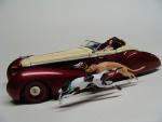
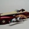
A few months ago, I posted in the “underglass†section, pictures and a video shot ( from my cell phone) of my 1999 Ford F150 Lightning pick up truck with a motorized retractable hard top. I received some interest on how the engineering works. I tried to write it out, but it is just too difficult to explain without pictures. The F150 is painted with a dark color so detail photos are tough. A year later I built another truck with a retractable top but it is a lighter color so the photos of the mechanics come out better. This is an AMT 1955 Chevrolet Cameo pick up. I molded the pickup bed to the cab of the truck and cut off the top. The top was made from a Revell Sidewinder roadster top cut into two pieces and hinged. The windshield is from a 55 Chevy coupe and the interior was custom built with a new console made from scratch. The truck was painted with Mopar Pearl White and the flames were hand cut from masking tape and painted with HOK pearls. Ok, enough about the truck. The point of this post is the mechanics. I drew out a sheet with a rough diagram of the way this works. It is fairly simple to do. There is one motor under the tonneau cover that moves a rod up or down, with a two way switch. The tonneau is first opened and then the top is raised. There is a motor under the truck that raises a rod ( letter D in diagram) that moves the top up or down. Rod D attaches to the top at tube C and B (tubes B & C are glued together) this moves the double pivoting hinge with is attached to the roof up or down, depending on the desired direction you want, up or down with the 2 way switch. The tricky part is to articulate the top into the out or open position and tuck it in as the roof is lowered into the closed position. This is done with a rod that you can clearly see in the photo. It pushes the top front section “out†in the open position when the top is up and pulls the top front section is tucked in when the top is in the closed section under the tonneau. This rod is attached to the truck body between the cab and the pickup bed and it is free to pivot over 180 degrees. I hope this explains the top a little better, and I will be happy to answer any other question, if there are any, on how this works. I figured the next time I build an articulating top, I will try and make it operate with a wireless remote, assuming I can acquire the micro gear-head motors I am trying to get. It is really not that difficult to do. Ok, I hope this helps.
-
Dave, very nice clean build of an old kit. ( I loved your tip on "whitening" an aged decal sheet....I never heard that before, but will have to give it a try) I have had this un-built kit in my collect for 12 years or so now. I was hooked when I saw that great box top painting, from Tamiya, showing all of the lines and fittings. I am sure many where inspired to replicate the box art, but I doubt that any did a better job then you did on this kit. Clean and professional.....well, maybe the tire lettering was a little bit heavy, that I think is a matter of personal opinion, but I love this build. Mine, if and when I get around to it, I hope comes out half as nice....that will make me happy.
-
 I just typed "lodging wayne nj" into google and hit more hotels and motels then you will ever need. There are at least 20 hotels within a few minutes of the PAL, which is just off of RT 23 near the intersection of RT 23, RT 46, and RT 80. in Wayne. I ( I live very close by )don't think there will be a big problem finding accommodations, you guys will have many choices of hotels and room rates. Just Google it.
 -
Raul, very nice job on the Merc. I really like to see the updated components added to the older car. In real life that works great. You get the ride,comfort and performance of a modern auto, with the classic looks and attitude of the older car. Nice color combo too. The purple works really well with the dove gray gut. I like the single color on the exterior...classy.
-
Nice build...I built this car about 4 or 5 years ago also, after I saw a story on it in RaceCar Engineering. I was not sure at the time because it was a curbside kit. But I agree with you that it built up to a nice shelf model and the colors look great next to other cars on the shelf. Nice build and nice job on the interior and underside. Looks great. Classic example of "less is more sometimes".
-
Hot, and I do mean hot off my workbench, is my 1967 Dodge Charger with airbrush True Fire Flames. This is my first attempt at scale true fire flames. Overall I am happy with the finished product, but now that I have done it, I expect my future attempts will be "tighter" and more concise. I love to try new things so I can learn the technique and improve on each new build. The car is painted in Tamiya Metallic Black as a base. The flames are also Tamiya paints sprayed with my airbrush using the smallest needle (#1) and the air pressure set down to about 25 lbs. I started with a red rough flame outline starter base, followed by bright orange, covered with clear orange. Then bright lemon yellow was applied using a set of stencils that I hand cut, based on the stencils that the professional 1:1 auto painters use. Looking back now, I will remake the stencils a little smaller. for my next go round with true fire. Than I went back over the flames with more orange and then yellow to sharpen up the flames. Once dried, I re-coated with clear orange. Each time you cover with clear orange you set the flames "deeper" into the fire so it makes the fire look deeper and hotter. Once dry, I laid down a thin coat of clear clear to seal the colors. Then I did one more touch up with bright yellow with the stencil and covered that with with clear yellow. Then I mixed up a batch of very thin clear blue and clear red and added a small ultraviolet "glow" around the back end of the flames. Once dry, I added 3 coats of Tamiya clear. (P.S. my first time using Tamiya clear with the airbrush, went on great, very smooth, but it does not want to dry. I think it is still wet and very impressionable. I will be more careful in the future using that clear). I almost destroyed the paint job with finger prints 8 days after the clear was applied. The engine was detailed with the usual wires and stuff. I opened the doors and used my "Dental Floss Holder" hinges, which I might add, worked great. The wheels/tire are Hoppin' Hydro's 20" Vortex #526 and the brakes are Pegasus #1093 19" disc's and et the body down as low as possible to the ground. I two-toned the interior with semi gloss black and a deep maroon red. Oh, also I opened the trunk, but there really isn't anything special about that. I am also working on my 2007 Ford Interceptor and will have a progress report on that after Christmas ( I know, big deal) Anyway, comments/complaints or questions are always welcome and guys, have a Very Merry "Plastic Filled" Christmas. I hope Santa brings us all what we want.
-
Great little trick there, I see many uses for the magnets. Nice job.
-
My 1rst Post-06 Mustang Anniversary Edition
Peter Lombardo replied to mikelo's topic in WIP: Model Cars
Great job...I really like the fact that you drew out the design first, and then built it to the design spec's. I really like the roof and front end treatment you chose and the color is perfect. Nice work. -
Comments welcome?....you want a comment?...I'll give you a comment.....I love it. I would never have thought of the GTO roof, but it looks nice, sittin' down low. I also like the idea of the tall narrow tail lights. Keep it going, I think you are on to something sharp here. Dark color or light, it will look nice, even if you did a satin finish, it would look good.
-
I have finished the doors hinges and have the doors interior panels in place. The doors still require a little tweaking to get the window frames lined up properly, but they are close. I glued spacing blocks to the inside of the doors so that the interior panels would rest the correct distance away from the outer skin. Once they set up, I mixed up a small batch of two part body putty and carefully applied it to the gap between the interior panel and the outer door. They were set aside to cure. I only do two doors at a time because there is a small window of opportunity after the putty is applied that you can easily trim the excess putty. The putty has a period of maybe three minutes after it sets up where it is easy to cut with an exacto knife. I take advantage of this period to run a knife blade around the outside edge of the interior panel to remove the excess putty, and no matter how careful you are, there is always extra putty to remove. Once cut to the basic shape, I sand the edge smooth. Any small air hole pockets are willed with model putty and sanded flush with the surface. You can see the brass rod hinges that I hand form for each application. The front doors pivot inside the fender and the rear doors swing out side of the outer edge of the doors. I use the same hinge, I just reverse the installation so that the front door pivots in, and the rear door pivots out. The hinges are made from .032 brass rod and they slide into 1/16 X .014 Aluminum tubes. This system works great for me because the doors can slide into place and I can make sure everything fits properly. I am beginning to work on the front and the hood. The front fascia will be permanently mounted t the piece you see just under the hood, then the hood will hinge from the front piece. In the last update, I mentioned the wheels from the Honda Civic SI. The other day I was looking at the snap fit Thunderbird and realized that they have 7 spoke wheels, so right now they are the leading candidate for the base of the Interceptors wheel centers.
-
Lyle, obviously this is a beautiful build...color, wheels, grill, everything is perfectly period correct....but the diamond tuffed interior looks spectacular. That really sets it apart from the rest. Beautifully executed as usual.
-
-
-
It has been a while since my last post on this project. I have been very busy at work, and my wife and I were able to sneak a few days away, so work on it has slowed. I haven’t even really had time to look at the forum much, but that is not important now. This, as I said before is a long term project. A modification of this magnitude doesn’t happen over night. On to the progress I have made. I have the overall body shape as close as I think I can get it from the reference pictures that I got from Conceptcarz.com. I have measured as many dimensions as I could from the pictures I have, than converted them into percents of the overall vehicle. Then I did the same on the model, converting the dimensions into percents. Any variance was converted into the proper measurement and adjustments were made. As I have stated before, this is as close as I can get considering I do not have the real car available to work from. Next step I had to deal with was the 4 doors. At first I thought I would just scribe in the door opening lines as the putty work on the sides was pretty extensive. But once I got started making the lines, I could not fight the urge to “dig a little deeperâ€. Normally when I open doors, I rely on my trusty Squadron Panel Scriber, a #11 knife blade and a small exacto saw blade fitted to a # 11 holder. But this body was so thick in many spots; I took my Dremel tool with a rounded grinder head and cut a deep trough on the inside of the door openings. This helped to even out the thickness and make the cutting bearable. The upper window frames were very difficult to say the least. Not only was the top chopped, but it had been moved inward, as the top greenhouse is not as wide as the original Chrysler 300. So cutting through all of the splicing was very tedious. I cut the doors out on each side intact, meaning that I kept them together and separated them once free from the body. Also, the doors have different lengths then the Chrysler doors have, so the cut between them is in a different place (does that make sense?) If you look carefully at the rear doors, you can see that they were cut just on the inside of the rear wheel wells. That was fine for the actual opening but the outer door skin flows all the way to the wheel well. This required extra support to the inside of the frame because I was going to have to grind down the outer section and add outer skin to the rear doors. I think you can see the addition to the rear door on the picture of the inside of the door. I cut a piece of sheet plastic to match the back contours of the rear doors, super glued it on and finished it with putty. Then I very carefully trimmed the outer skin to fit. It was made more difficult because there is a “flat†edge that runs around the wheel well openings, so it needed to be built up. I fabricated the two posts that separate the front and rear doors out of small strips of plastic and once the rear hinges are built, they will be finished on the inside with the piece that I cut free from the interior side panels. The hinges will be difficult on this on. Usually, the hinges are straight forward, but because of the curves on the sides and the extra work I had to do to the front area by the hood; the hinges will be rather complicated, but certainly do-able. Next I tackled the hood and front fascia. To cut the hood free, I had to fabricate inner supports because the hood tilts upward and forward and the hood opens all the way down to the side accent ridge almost half way down the side. So the space between the lower body side and the windshield needed to be supported before I cut the hood free. I was concerned that the windshield would not be in the correct spot once the hood was cut free so I took extra care here to secure it first. Once free, I added the front wheel well tops and the access panel that runs between the wheel well and the firewall. After that was installed I began fabricating the curved firewall. This is a multi-piece unit that is being built in place, so there is a lot of cutting and fitting going on. The top portion has a grill, to let air into the ventilation system, I presume, so that will be added last. Now I began working on the engine. The actual car has the modular Ford 4.6 liter V8, same as the Mustang GT. In fact, the Interceptor is based on an extended Mustang platform. Fortunately I have the 4.6 engine from the Revell Mustang GT that I did not use on the Shelby GT 500 conversion I did earlier this year, so that will fit in nicely. I need to scratch build the correct head covers and the intake system will need extensive modification because the air cleaner sticks up through the hood. Next the front grill, headlights and bumper assembly will be tidied up and/or built and attached to the front of the wheel well openings. I have no idea what the real chassis looks like (stretched Mustang), so the slightly modified Chrysler 300 chassis will be pressed into service. The interior will require extensive scratch building but that can wait until the body has moved along. I still need to cut out the taillights and make the exhaust openings below the taillights. The last big item after that will be the wheels. There are not a lot of 7 spoke wheels around. I have not found any aftermarket 7 spoke wheels of the correct size yet. Anybody know of any? What I have found are the Pegasus #2399 Aluminum Stepped Sleeve wheels. These are 23 inch wheels with great big wide tread. The Revell Honda Civic SI Coupe from a few years ago has a set of 7 spoke wheels in it. If I grind down the raised ridge on the center of the outer diameter of the wheel, it will slip into the Pegasus sleeve perfectly. The shape of the spokes is not exactly right so modifications will have to be made, and they are 4 lug wheels which need to be made into 5 luggers, but that is do-able. Ok, as usual I have run long again, sorry, but there were a lot of modifications to catch up on. This build is another tough one, but no pain, no gain. I really enjoy solving problems as they arise. Every challenge overcome is a new technique learned. I am learning a lot these days. I know the front grill and headlights will be a mid term exam.
-
http://www.modelcarsmag.com/forums/index.php?showtopic=6190 I am sure there are many ways to build "Lambo" door hinges. This is how I did it a few months ago. If you copy this link, you should go to the Chrysler 300C Touring Wagon that I built using Lambo hinges on the front doors. This is posted September 1, 2007. This was a very easy way to build them. Also good for your teeth and gums. P.S. If this link does not get you there, the post is on page 12 of the "under glass" section.
-
Real Or Model #9 Finished!
Peter Lombardo replied to Harry P.'s topic in Real or Model? / Auto ID Quiz
Voted real for all of the same reasons sited by everyone else. But if this is a model...the line is not just bleared...it is blown to hell. -
Fujimi Ferrari 330p4...
Peter Lombardo replied to Captain Obvious's topic in General Automotive Talk (Trucks and Cars)
I built one about 10 or 11 years ago. It is a very basic kit to build as there were no surprises. As I am sure you know, it is a curbside kit with fairly simple interior and suspension moldings. The kit is basically the exact same style and layout of the great Ford GT 40 kits. It has a very nice body molding and is simplistic underneath. I got a little crazy on mine as I installed an engine from the Union Ferrari kit of the same car (it has a nice motor but a suspect body molding), I opened the doors, not easy, and opened the front hood(fenders) and the rear engine cover. I plan on getting another kit and making a rather simple conversion to the roadster version of the car. This one will forgo the door openings and engine. Get the kit, most people in the know say it is the most beautiful Ferrari, race or street, ever built. Beauty is in the eye of the beholder, and I agree with most, it is as sensual as the Jaguar XKE in my eyes. There is something about a curvaceous redhead with an amply rounded rear end that gets my motor racing. -
Thanks Erik, basically I use 2 types of putty and 1 sealer technique. The “big†putty jobs start with auto body putty. It is made by Bondo, I get it at an auto parts store. It is a two part putty that needs to have a very small drop of hardener mixed into the base putty (That is the pinkish colored putty). I have used a few different brands and I can’t really tell any difference. Actually, the only difference is the color, some are light tan, some are gray. One can of this will last months, in fact you will throw away the last ¼ of the can before you use it, just because it is so old. You may go through a few tubes of hardener though, but it is very cheap. Because these use a chemical reaction to harden, there is no shrinkage problem. A few years ago I converted an Accurate Miniatures Grand Sport Corvette coupe into a roadster. I used good old model putty. It looked great, nice and smooth so I painted it. Nice paint job, and then a few days later, the putty shrunk and I had a nice trough shaped V on the rear deck from where the coupe fastback roof was. I learned a valuable lesson that day. I now use the 2 part putty for the heavy lifting and I use the Tamiya (gray putty in the pictures)(great stuff) for the fine tuning and small jobs. But be careful as even this will shrink a little because it evaporates the carrier agent in the putty as it dries. The Bondo stuff sands great and the Tamiya putty is even easier to sand, as both respond well to wet sanding. The “sealer†I use is something that I just stumbled on myself (I think, I have not seen this before). Once I have the putty to a point where I am happy with the surface, I coat the surface with super glue. I use the thinnest grade glue they sell. I just work it on to the putty either with the top of the bottle or, if it is a big job, I will “glop†it on and use the back end of a paint brush or a piece of wire/brass rod or even a small piece of stock. Sometimes I use an old tee shirt to work it in. How you spread it is not very important, what is important is that you make it as smooth as possible so there will be less sanding later. My logic, right or wrong, is that I think the putty is a little soft and a little porous. The very thin super glue( in my opinion) fills the small holes and strengthens the putty. I will put it this way, in the few years that I have been doing this, the only down side I can find, is that I buy a little more glue then I used to. No biggy. Once dry, I wet sand as usual and get a nice smooth surface for a coat of primer. I have even applied the glue over primer and not had any problems from that. Sorry, I went a little long on it, but it may help you.
-
Wow, great flames. Very different build for a 59 Caddy. Sure got that "chrome thing" happening too. Interesting, nice to see a 59 Caddy that isn't Pink. I have the kit and have yet to get the inspiration to know what I want to do with it. Obviously, you found your inspiration. Nice.
