Robbo
-
Posts
43 -
Joined
-
Last visited
Content Type
Profiles
Forums
Events
Gallery
Everything posted by Robbo
-
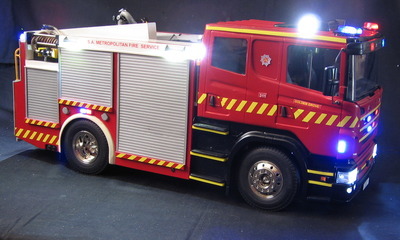
1:14 scale RC SAMFS Scania fire truck.
Robbo replied to Robbo's topic in Model Trucks: Big Rigs and Heavy Equipment
Thanks for the comment. Yes, it can be driven, but does not pump water. See the complete build & video clips at: http://public.fotki.com/Supt-Robbo/scania-114-scale-rc/ and the 'Run in carport' on Youtube; https://www.youtube.com/edit?o=U&video_id=IV3FB4DmYdA -
A very well executed model with a superb paint finish.
-
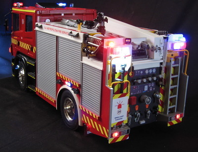
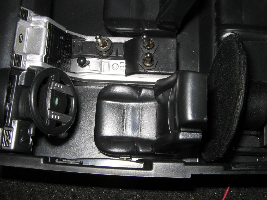
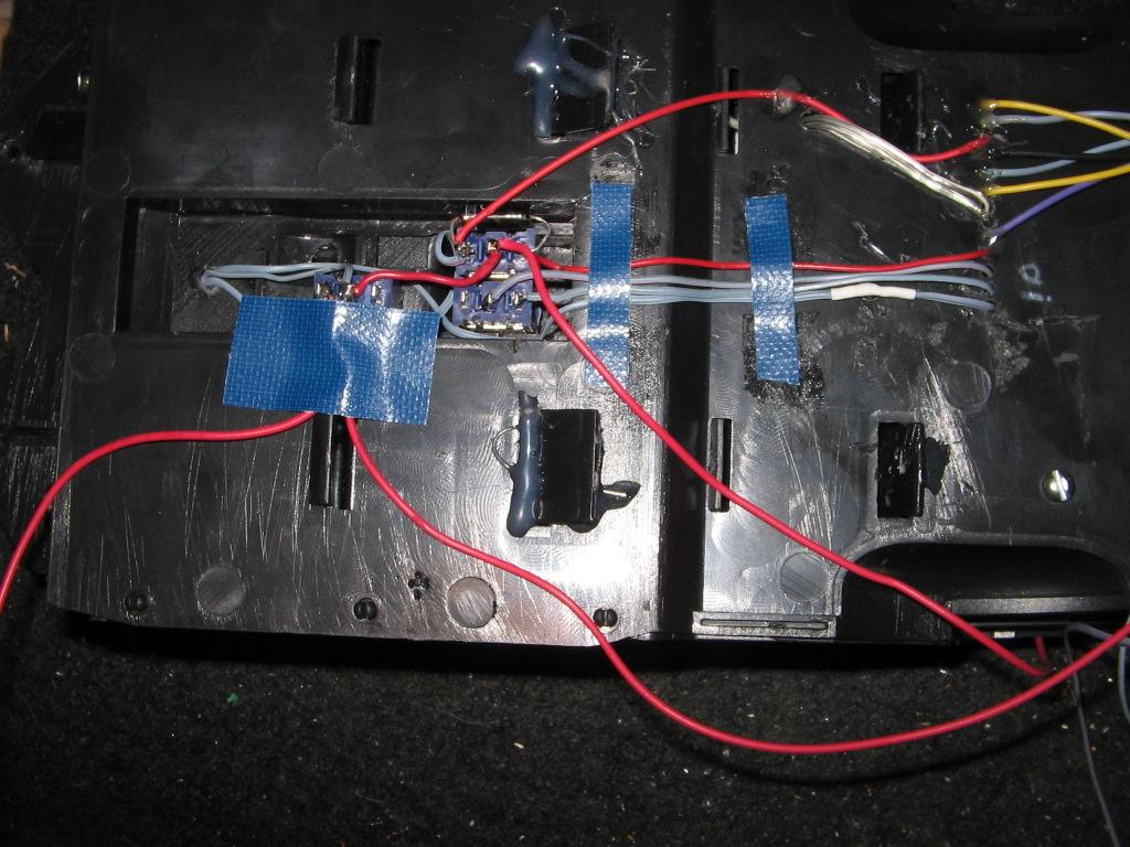
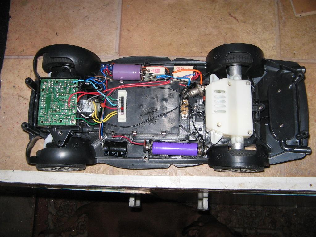
Cab is from a two door high-top Scania Tamiya kit, modified to a four door cab. The chassis which was to be for a semi trailer configuration was modified to carry an extra battery to power the head/ tail, auto reversing and stop lights as well as the emergency flashing lights, spot/work lights, horn and siren. All of the circuit boards are housed in the cabs with the horn and siren speakers mounted in front cab roof. The power train comprises an electric speed controlled motor, 3 speed gearbox and true differential driving the rear wheels. The rear cab , ladder, hose reels, nozzles etc. were completely scratch built. The whole project took just over twelve months to build, starting late February 2016. The ladder locking/release mechanism is operational and the hydrant hard hose cabinet houses the battery charger connecting cables. Last picture is titled: 'David meets Goliath'. For a complete view of the build and video clips, go to: http://public.fotki.com/Supt-Robbo/scania-114-scale-rc/

-
I'm also currently converting a 1:16 Bruder model Mercedes Sprinter horse float into a bariatric ambulance. Took some stripping as no screws are used, only strong plastic clips. Google - Bruder and Dickie toys for the various large scale Sprinters available, which can be stripped, converted and partly scratch built to your liking. The smallest that I have put lights into is a diecast 1/32 Sprinter. Have fun finding and converting. Robbo.
-
-
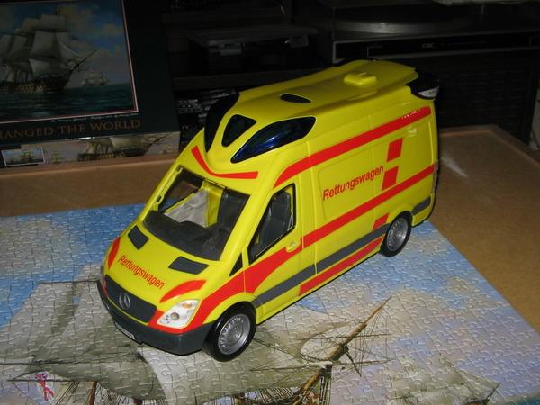
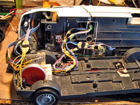
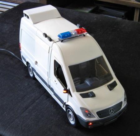
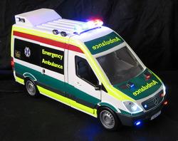
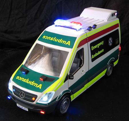
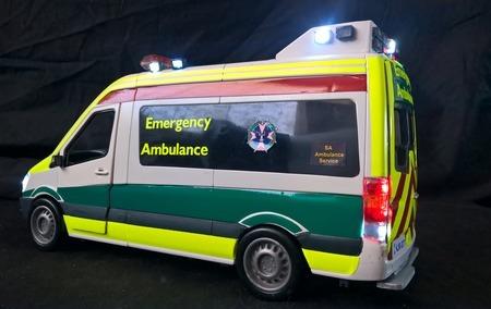
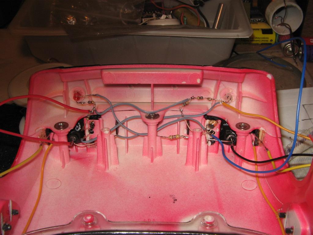
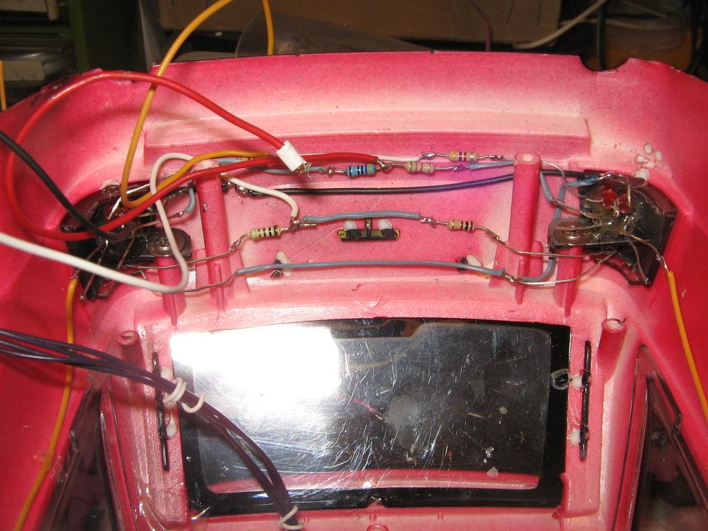
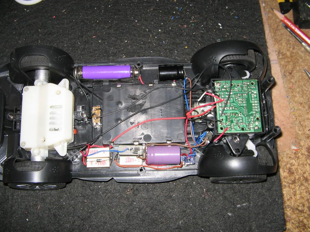
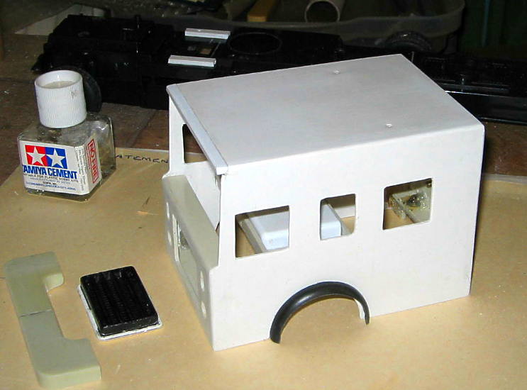
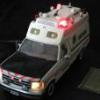
This project started 18 months ago with the design, construction and the making of electronic circuit boards for the flashing lights and siren. The body is, in the main, a model Sprinter ambulance with an entirely different roof styling. (see first pic) The original roof was discarded and the rear cabin body modified and partly scratch built. The whole original model was completely stripped and repainted. The final red, green and yellow colour panels are self-adhesive reflective sheets of thin PVC material. The colours are those of the SA Ambulance Service.The rear, front and side flashing lights are made from discarded calculator buttons fitted with Fresnel lenses, as are the 7 spot lights. A total of 56 high intensity LEDs and 10 standers intensity LEDs are used for the lighting. Opening of doors switches ON interior lights. The rear view mirrors are fitted with amber LEDs and Fresnel lenses. For a more detailed view of construction and a video clip, use the following link: http://s254.photobucket.com/user/Robbo2008_70/library/Mercedes%20Sprinter%20Amb%202014?sort=6&page=1 Cheers from Robbo.
-
Very nice builds, detailed and finish. Robbo.
-
This project has taken quite awhile to get all of the components to fit. Purchased a 1:14 scale model and stripped it right down to component parts. Drilling out the front and rear light assemblies to fit the appropriate LEDs, positioning switches and PCBs as well as fitting the LEDs into the light bar, were quite a challenge. I trust that you will find this of interest. More pictures to come as progress is now quite rapid. Cheers from Robbo
-
Scania trucks in the US?
Robbo replied to Chuck Most's topic in General Automotive Talk (Trucks and Cars)
Scania is a very popular truck here in Down Under Australia. Here in South Australia, the Metropolitan Fire Service use them as an all purpose rescue pumper fire appliance. They look great. -
Scale rc trucks i built over the years
Robbo replied to Prostreet's topic in WIP: Model Trucks: Big Rigs and Heavy Equipment
I like it, great detail. Robbo. -
R/C Fire Rescue Truck
Robbo replied to Robbo's topic in WIP: Model Trucks: Big Rigs and Heavy Equipment
Thank you Matthew (MCM Ohana). I originally tried to post the direct link, however it would not display properly and would not work, even after several attempts, whereas the site address did, so I stuck with that. For some reason when using this forum, I can not 'cut and paste' any text etc. Tried again to edit with the same result. Cheers Robbo. -
WOW!!! What a great display and show of modelling skils. Just shows what can be done when a number of bods get together. Must have cost a mint. Perhaps some ailines chipped in to sponser it> Cheers from Robbo.
-
Finally completed after having to modify the rear suspension springs and motor control circuit, due to the overall final weight of the model. 1.64Kg (4.66Lb) Full details, pictures of the build and a video clip can be seen on my PhotoBucket site: http://s254.photobuc...8/Robbo2008_70/ Just browse the index to locate this project. Click on 'View All Albums', it's the last one. I trust that you will find this interesting. Cheers from Robbo.
-
Hi Joe, that is just one great model and so well built. It's a credit to model building. Cheers from Robbo.
-
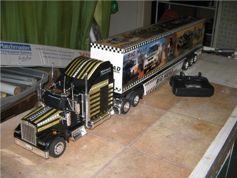
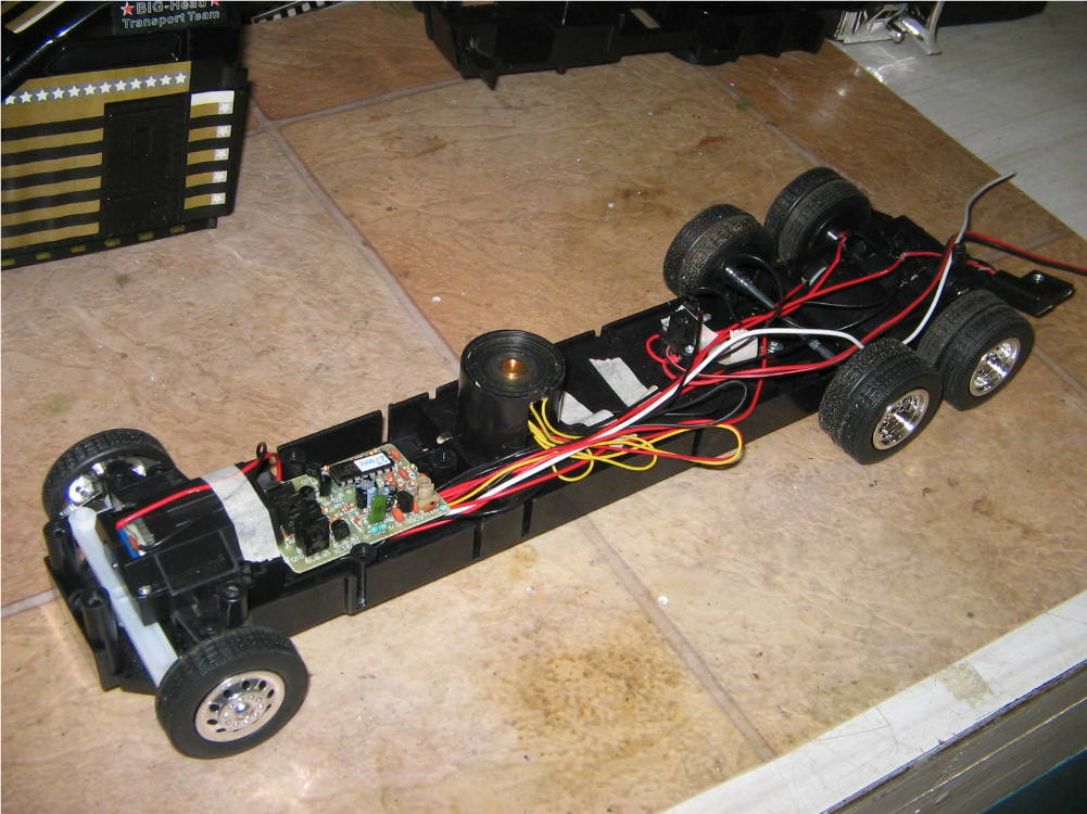
Hi there Rodney. The chassis is from an R/C Kenworth truck, purchased just for the nitty gritty bits. e.g. the chassis and the radio control system. Currently I'm working on the electronics for the head/tail, emergency lights, siren, spot lights, back-up warning etc. Cheers from Robbo.
-
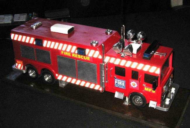
Hi all, just a few pictures of the latest project, a R/C fire rescue truck just about ready for the paint job. The electronics design for the flashing lights, siren etc are well under way also. The roller shutter door at rear is to have narrow slats glued on to improve scale. Cheers from Robbo. [attachment=11491
-
Great work, very impressive. Keep practicing. I also have problems with adding striping etc. Cheers from Robbo, a fellow Aussie.
-
I'm into building model ambulances, police and fire service vehicles. Your model of the Ford F-250 looks a great scratch build. Robbo
-
Great paint job and realistic finish. Well done. Robbo
-
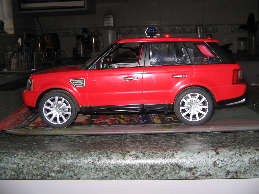
Well its been a while since I've posted to this forum. I am amazed at the diversity and expertise of the various contributors to this forum, especially their skills in making the model looking like the original with brilliant paint work. I must admit my paint work is not as good, but at 72 years of age, I don't think it is going to improve. I do not have air-brush equipment, but use spray can enamels and various art paint brushes for some jobs. I use genuine reflective self adhesive plastic sheeting offcuts for the livery. I purchased the F-350 as a radio control toy for Aust $37.50. It had red LEDs for head and tail lights, yellow turn indicator LEDs above each front wheel, a speaker in the rear deck ( which played tinny music) and was surrounded by four flashing colored LEDs. The head and tail LEDs also flashed when the vehicle was in motion. A tinny horn sound was also featured as well as the doors being remotely opened. I stripped the F-350 completely and diced the music/horn/flashing light circuit board and sorted out the 27mHz receiver channels to control the various functions in the rescue truck. Forward, reverse, left and right turn functions were kept as is. Additional holes were drilled in the front and rear head and tail light assemblies to accommodate small LEDs for turn indicators and stop lights. The link for web site of the model, with pictures; showing painting, construction, reflective plastic livery panels and two videos is: http://s254.photobucket.com/albums/hh108/Robbo2008_70/F350%20Rescue%20Truck/ Pictures are best viewed as a slide show, to display the descriptive text. I trust that some of you will find this of interest. Cheers from Robbo
-
Electronic Circuits For Models - Error apology.
Robbo replied to Robbo's topic in General Automotive Talk (Trucks and Cars)
orry, the link worked when I first posted. Redone, now OK. Cheers, Robbo. -
Electronic Circuits For Models - Error apology.
Robbo replied to Robbo's topic in General Automotive Talk (Trucks and Cars)
Sorry, the link worked when I first posted. Redone, now OK. Cheers, Robbo. -
Hi all modelers, some time ago, I posted links to my PhotoBucket site, that lists circuit diagrams to bring models alive. Recently, when making up PCBs for a new project, I discovered errors in two of the circuits. Circuit 3, Double flash simulates aircraft Xenon strobe lights. The +ve voltage lead connecting the two multi-vibrator sections was omitted. This has been rectified. The lead connects from the anodes of LEDs 3 and 4. Also, resistor R6 value (33K Ohms was omitted). Circuit 5. Similar to circuit 3, the +ve voltage lead connecting the two multi-vibrator sections was omitted. This has been rectified. The lead connects from the anodes of LEDs 3 and 6. I produce the circuit diagrams, using a software program and as the circuits are similar, I used circuit 3 as a template and added the extra components. Apparently I omitted the +ve link and missed it when finally checking. Please accept my apologies for any inconvenience. The link is: http://s254.photobucket.com/albums/hh108/R...nic%20Circuits/ Cheers and good modeling, Robbo Oops
-
Hi there MrObsessive, sure, we used to have cats and they sort of got used to it. We now have two dogs who now don't give a toss when the sirens sound. Cheers, Robbo.
-
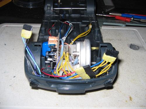
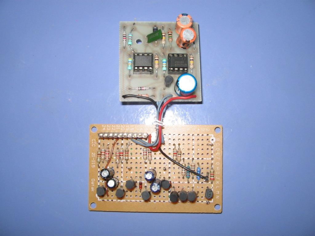
Hi there Evilone. I do all of my own electronics and custom make the PCBs to fit each particular model. Sometimes, as in the Sprinter, I have to place components away from the PCB to fit them in, where space is limited. My circuit diagrams, which include strobe flashers, turn indicators, 4 way hazard lights etc., are posted on PhotoBucket site, link: Electronic Circuits for Models http://s254.photobucket.com/albums/hh108/R...nic%20Circuits/ More Electronic Circuits for Models http://s254.photobucket.com/albums/hh108/R...nic%20Circuits/ You can navigate from there to my other models which include police cars. I suggest that if you have problems with electronics, enlist the help of friends who are into this hobby. Only to pleased to help further the hobby. Cheers, Robbo.