Mooneyzs Posted December 12, 2016 Share Posted December 12, 2016 Paul... you are more than welcome. if you weren't 3 hours away from me I would of been more than happy to show you things in person. You know I am always here if you need me. On a 2nd note.... I think I may have rubbed off on you of you are tearing down part of the chassis and redoing it . you could always go yhe brabrass route. I just wish I would of scratch built the whole F/C chassis instead of 95% of it. I know this chassis will be way better going back and redoing it. The hard work will pay off. Quote Link to comment Share on other sites More sharing options...
511 nova Posted December 14, 2016 Share Posted December 14, 2016 Don't know if I missed it or not but do you sell 3d printed parts. How do I look them up Quote Link to comment Share on other sites More sharing options...
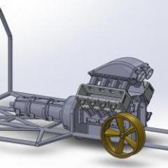
mr68gts Posted December 15, 2016 Author Share Posted December 15, 2016 Back to the drawing board! I had a couple minutes this morning so I redid the print for the chassis floor and main rails. The new hoop is glued into the main chassis and I am waiting on some dimensions to show up, (thanks again!) to set the cross bar in the hoop. I've started machining the insert to properly space the 4 link brackets out the proper distance according to the rear end. Before I know it it's going to be a complete chassis again even though much of the old one I can't use on this version. I can salvage some of the tube though. I need to look at the wheelbase on the body again so I can find the mid plate location according to the 481x I've drawn up. (10% setback from number 1 plug) I'd like to draw up the mid plate to use as a template to cut out in sheet plastic although I may use aluminum sheet instead. Quote Link to comment Share on other sites More sharing options...
Mooneyzs Posted December 15, 2016 Share Posted December 15, 2016 Hi Paul... I have to give you credit going back and redoing things To me it makes total sense to draw the chassis up and place the engine in to get the midplate location. the time spend up front designing will only help with the fabrication. I know I can't wait to do that on some future projects. I love what you are doing, you are rocking this build for sure. can't wait to see more. Quote Link to comment Share on other sites More sharing options...
mr68gts Posted December 15, 2016 Author Share Posted December 15, 2016 Hi Paul... I have to give you credit going back and redoing things To me it makes total sense to draw the chassis up and place the engine in to get the midplate location. the time spend up front designing will only help with the fabrication. I know I can't wait to do that on some future projects. I love what you are doing, you are rocking this build for sure. can't wait to see more.Thanks Chris! It's a bit more time consuming this way however it will be correct and square since it's all engineered on the computer!Paul Quote Link to comment Share on other sites More sharing options...
blackbeard Posted December 15, 2016 Share Posted December 15, 2016 that's going to look great Quote Link to comment Share on other sites More sharing options...
comp1839 Posted December 15, 2016 Share Posted December 15, 2016 i have to agree with chris, paul. absolutely time well spent!! looking VERY good. Quote Link to comment Share on other sites More sharing options...
mr68gts Posted December 16, 2016 Author Share Posted December 16, 2016 Thanks guys.Boy I'll tell ya what, reading the NHRA rule book is like reading the bible! There's a lot of deciphering going on! Having to flop between the NHRA and the SFI book has given me a head ache lol.Paul Quote Link to comment Share on other sites More sharing options...
Mooneyzs Posted December 16, 2016 Share Posted December 16, 2016 Paul... Being able to plan and engineer things up front may be a bit more time consuming but it will allow you to confront some problem areas and address them prior to any building. It would reduce any reworking of some items for sure and once parts are fabricated things should pretty much fit like a glove. There may be a few things that may have to be tweaked but you could always add some extra clearance in a few areas to consider paint and some stack up of items. I am sure reading those books would make your head spin after a while. Quote Link to comment Share on other sites More sharing options...
mr68gts Posted December 17, 2016 Author Share Posted December 17, 2016 OK, what you are looking at is a "quadrant bolt". What these pesky little suckers do is make it near impossible to get the clutch can on or off when you are in a hurry. There is one is each corner and required on all fuel cars, I believe all alcohol cars (not the kind you drink!) and most if not all pro mods. They are actually in real life 3/4 or larger studs that are pressed into the mid plate and help retain the can in the event of a blow back. Keeps the can where it's supposed to be basically. I've had my fair share of experience with these buggers so what do I do, make em for the model! Ha ha. One down, 3 more to go. I searched the SFI spec for this for a bit to come up with the dimensions and yes it is to print in scale! Quote Link to comment Share on other sites More sharing options...
mr68gts Posted December 17, 2016 Author Share Posted December 17, 2016 And, I may wind up using my own rear end instead of the TDR one. I will have to machine the spindles for it though to give it some strength. One of the inherent issues with 3d printed parts is there is not a lot of strength in the parts depending on material. What hold the wheels where they need to be is one place I do not want to skimp on material. I'm not to worried about how much the model weighs. Quote Link to comment Share on other sites More sharing options...
blackbeard Posted December 17, 2016 Share Posted December 17, 2016 those little buggers look great and that rear end is killer looking Quote Link to comment Share on other sites More sharing options...
futurattraction Posted December 17, 2016 Share Posted December 17, 2016 Paul, I have a resin cast version of a 1/16th FAB9 type housing, along with PE 4-link brackets I would send to you so you can see if they would work for you. I can send pics via PM if you wish. Quote Link to comment Share on other sites More sharing options...
Ace-Garageguy Posted December 17, 2016 Share Posted December 17, 2016 This just gets better and better. Gotta hand it to you for hacking into a beautiful chassis and essentially starting over to get it more-right. Always gratifying to see guys work who care this much. Quote Link to comment Share on other sites More sharing options...
mr68gts Posted December 18, 2016 Author Share Posted December 18, 2016 Thank you Bill. I figure if I am going this far I might as well make it right. It really only takes a little bit more time to build an "accurate" model. Little bit of an update. I've got the engine placement and wheel base done. I need to change the bell housing up though. The depth is correct but the diameter is off and there are no mid plate studs in the model which correspond to holes in the bell housing obviously. Neat thing about all this cad work is I can even figure out the length of the 4 link bars and build a fixture accordingly! (the real reason I am doing all this cad work! No guessing, just accuracy as long as I follow the map lol)These 4 link brackets are a bit different in that they are more modular but they are the correct height and should alleviate a ton of problems with clearance issues with the driveshaft etc. Quote Link to comment Share on other sites More sharing options...
Codi Posted December 18, 2016 Share Posted December 18, 2016 (edited) This is amazing. I saw over the weekend a 70's pro stock chassis from TDR printed in 3D in metal. I ordered one because I want to see how far the technology is progressing. Just to be clear, too cool what you're doing here and something else I'd like to learn. Sent you a PM btw. Cheers, Tim Edited December 18, 2016 by Codi Quote Link to comment Share on other sites More sharing options...
comp1839 Posted December 18, 2016 Share Posted December 18, 2016 i am officially "jealous"!!! Quote Link to comment Share on other sites More sharing options...
mr68gts Posted December 20, 2016 Author Share Posted December 20, 2016 Tim, if you do decide to get into it Ill help you any way I can. Dave, thank you but it is your work that has made me push my own limits. For this I thank you and it is I that should be jealous! So I managed to do the stud placement on the mid plate. I still need to add the coresponding holes for the bell housing bolts and there are 2 vent holes allowed in the mid plate for cooling. Before I print it out on paper I will draw lines through the center of each hole and use it as a template to drill the .02 thick aluminum sheet. Then install the studs or quandrant bolts. Quote Link to comment Share on other sites More sharing options...
comp1839 Posted December 22, 2016 Share Posted December 22, 2016 paul, which bolt pattern are you going to use? don't know if it helps, the o.d. on the bell housing is around 14.500" -14.625". just measured one today. Quote Link to comment Share on other sites More sharing options...
Mooneyzs Posted December 22, 2016 Share Posted December 22, 2016 Paul... that is some grate work you are doing with getting the engine in the chassis and location for the midplate. the midplate looks great as well. I like the idea of printing it out on paper and using the paper template..was going to suggest printing the midplate and you can use that as a template as well. keep up the great work. Quote Link to comment Share on other sites More sharing options...
mr68gts Posted December 22, 2016 Author Share Posted December 22, 2016 paul, which bolt pattern are you going to use? don't know if it helps, the o.d. on the bell housing is around 14.500" -14.625". just measured one today.Dave,I was going to do a Chevrolet pattern, (whats in the modeled mock up) however because I added the 4 studs it will now be a dual pattern 8 5/8 deep. I have a print for the Chrysler pattern also so it should be easy to add. I think I did the diameter at 14 but I'd have to check when I get home tomorrow night.Paul Quote Link to comment Share on other sites More sharing options...
Codi Posted December 22, 2016 Share Posted December 22, 2016 Thank you Paul for sharing not only the thread, but answering my other questions and offering to help. That's very generous of you. Cheers, Tim Quote Link to comment Share on other sites More sharing options...
mr68gts Posted December 24, 2016 Author Share Posted December 24, 2016 Just want to wish everyone a Merry Christmas. Looks like we are getting a white chrsitmas this year....hopefully.Be back on this in the coming year.Paul Quote Link to comment Share on other sites More sharing options...
mr68gts Posted January 2, 2017 Author Share Posted January 2, 2017 Got a few minutes before bed. Managed to get some of the reliefs in the brackets. I'd like to finish these up and get it uploaded along with a few other things so I can get them ordered. Quote Link to comment Share on other sites More sharing options...
mr68gts Posted January 2, 2017 Author Share Posted January 2, 2017 So, with the brackets finished up I've uploaded a single part to Shapeways to see about print ability. We will see what they say. I really cannot continue on with the chassis until these are done and in so I will be in hiatus mode finishing up the commission work until these show up. (few things I need to get finished up over the next week) Quote Link to comment Share on other sites More sharing options...
Recommended Posts
Join the conversation
You can post now and register later. If you have an account, sign in now to post with your account.
Note: Your post will require moderator approval before it will be visible.