Dale361 Posted March 17, 2023 Posted March 17, 2023 Holy Cow! Your replica and the real build. Incredible. Wish I had the skill shown in both builds...
Scott Colmer Posted June 20, 2023 Author Posted June 20, 2023 It's been a long time since I updated this project. We finally have paint! What you see here is the rearend with the scratch built calipers. There are brake pads in there. There is also the Optima diesel battery (Red top), Fuel cell with retainer, and compressor for the air bags. I'm running brake lines now. 2
cifenet Posted June 20, 2023 Posted June 20, 2023 These scratch built components are super sweet! The vented brake rotors came out nice too. Great job!
Scott Colmer Posted July 21, 2023 Author Posted July 21, 2023 Finally starting to attach stuff the the chassis! In order to have the most room to work, the chassis needed to be plumbed first. On the driver's side is the brake system while the fuel system runs down the passenger side. I opted to go with an electric fuel pump and fuel regulator because I'm not sure how Louie is going to run his. He cleaned off the front of the engine. I researched diesel fuel pumps for the design. There is a lot of chrome because Louie seems to like the stuff. The brake and fuel lines are silver "soft" wire from Micheals jewelry section. It come on a roll, so it needs to be straightened. That starts with pulling on it HARD. Then it needs to be tweaked with tweezers to get it as straight as possible. Bending is a matter of laying the wire up to the chassis and bending right angles (or less) over a set of Tamyia tweezers. I had to redo the long brake line because I made it too short. The fittings are all hand made using Plastruct hex rod. Molotow chrome is brushed on in two light coats. The battery cables just tubing. I fed the positive into a larger piece of tube and then ran it into the frame so the ugly black line would be hidden. One thing I worked at was not crossing any lines. The rear half of the brakes lines are in and the battery negative cable is mounted. The master cylinder is scratachbuilt to match the one Louie is using. Here are the fuel delivery and return lines ready to install. The are little, chrome mounting brackets made from Evergreen L shaped rod. Keeps everything lined up. Big leap forward. The Air Ride tank and battery are installed and plumbed. T The positive battery lead goes right into the frame. The rear brake line is in place, waiting for the flex line once the rear end is in place. Front brake lines are ready to receive the flex lines. I'm trying to get the chassis done before school starts. 1
Scott Colmer Posted July 24, 2023 Author Posted July 24, 2023 Got the reared hung. It starts with the mounting joints. These replicate what Louie had. The are giant rubber bushed rod ends on a airbag suspended four link. The first step is putting the bushings in place using hand made bolts with threaded ends and nuts. They are made from styrene hex rod sliced into nuts and bolt heads and the shanks are thin aluminum rod rolled under an angled exact to make the "threads." The next step was to slide on the rods of polished aluminum with the styrene jamb nuts. Ready to connect the other to the chassis. After some trimming of the rods the read end is finally mounted. The rear shocks and a couple bolt heads are still left to go. The gas filler is just set in place. It will be one of the last parts because it need to line up with a hole in the bed cover. Thanks for looking. 2
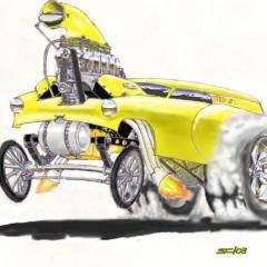
Scott Colmer Posted July 29, 2023 Author Posted July 29, 2023 Steve, Steve, and Dale. I am glad you are enjoying this project. Detail and design are my favorite parts of model building. I appreciate your feedback. The last few days are do-over days. It's all parts. Front caliper mounts. Not seeing the front disks or calipers on the car meant I had to fake it. For some reason, I decided to do my research 7 years after I made the caliper mounts. It took a while to actually find what brake system Louie used. The dip in the front axle gave me the clue. Then once I saw the mounts, I had to watch YouTube videos to see how the caliper attached. It is held in with a wedge plate. Here are the revised mounts with the locating arms extend above the rotors. The calipers have been grooved inside to fit on the tops of the mounting arms. Next up are the rims and tires. Several years ago, I widened a set of the kit tires and rims. The rubber on the tires is soft and getting the center piece to line up was hard. I ended up using a plastic tube inside. I thought it looked pretty good, but when I showed a friend of mine the tires, he said "Yeah. I see the seams where you glued them together." Strike one. The mounting on the Revell kit tires is weird. So much so that is a thread about it in the forum. When it can time to mount the widened tires to the widened rims, they would not seat up. Fortunately I bought some back up from Mobius. The looked a lot better but the rims were too wide and took a lot of work to get both beads to seat. The picture shows the seated Mobius rim and tire on the left, Uncorrected Mobius center. Abandoned kit product on the right and in the rear. And finally, the rear shocks. I must have been rushing, because I knocked out a pair of rear shocks without really comparing them to the real thing shown below I knew The shocks looked fat, but I continued on. Once they were in place, I hated the way they looked. So I went back and used K&S tubing to make a better pair. The old ones are on the left. New ones are on the right. The black parts on the mounts are edges are the rubber bushings. Because bushings matter. : ) Mounting the front end is coming up.
Recommended Posts
Create an account or sign in to comment
You need to be a member in order to leave a comment
Create an account
Sign up for a new account in our community. It's easy!
Register a new accountSign in
Already have an account? Sign in here.
Sign In Now