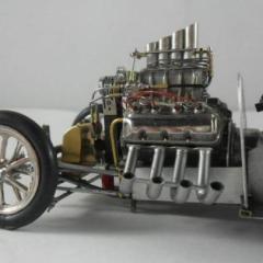
10thumbs Posted July 3, 2015 Share Posted July 3, 2015 Hi guys, Take a look here at the front end of this car. Is it sprung? How do these setups work? It can't be solidly attached to the frame, or is it? Could anyone explain how this setup functions, I think I've seen similar on hotrods but I'm unfamiliar with the deal. More pics are here: http://mikesullivanracing.com/news.html Thanks in advance, Michael Quote Link to comment Share on other sites More sharing options...
bismarck Posted July 3, 2015 Share Posted July 3, 2015 (edited) Looking at the pictures, it looks like they used a torsion bar setup like the early VW bugs had. Pretty slick setup. Edited July 3, 2015 by bismarck Quote Link to comment Share on other sites More sharing options...
2002p51 Posted July 3, 2015 Share Posted July 3, 2015 I think the OP is asking about the front suspension. This looks like a torsion bar set up. Same as that on the Revell funny cars of the seventies. Quote Link to comment Share on other sites More sharing options...
bismarck Posted July 3, 2015 Share Posted July 3, 2015 Yeah. I figured that out after i re-read the post. I went back and changed the comment. Quote Link to comment Share on other sites More sharing options...
Ace-Garageguy Posted July 3, 2015 Share Posted July 3, 2015 (edited) This is the only photo of the bunch that gives an easily-interpreted idea of the front suspension layout. There appears to be a transverse torsion bar, probably anchored in the center of the lower transverse chassis cross-tube, that is connected via heavy-ish forward-facing bellcranks and drop-links welded solidly to the underside of the axle. There could be two parallel transverse torsion bars. This setup was fairly common on a lot of cars, including something quite similar on many Indy roadsters. The torsion bar links function to locate the axle side-to-side fairly well, and there also appears to be a normal hairpin (looks like, in some side shots...though I didn't spend any time carefully analyzing them) that would provide fore-and-aft location of the axle. Rather than having a full hairpin on each side, it's also possible there's only one top longitudinal link per side, as a hairpin would tend to jam the geometry of the torsion-bar linkage motion, whereas a single top link would not. A single top link would allow the torsion bar linkage below the axle to function as part of a parallelogram linkage that would fully control fore-aft motion of the axle. It doesn't take terrifically sophisticated or strong linkage bits, as there are no front brakes with heavy loads that would need to be resolved into the structure. Here's a somewhat similar setup that uses full hairpins on each side. Similar setup, but with only a single longitudinal top link. Edited July 3, 2015 by Ace-Garageguy Quote Link to comment Share on other sites More sharing options...
10thumbs Posted July 3, 2015 Author Share Posted July 3, 2015 Torsion bars. OK guys, this helps. What makes the torsion aspect function? Is it hydraulic that provides pressure to keep things in line, or hard rubber? I don't have a clue. Bill, I can understand though what you wrote, and I really like the clean setup, great for my new project! The last pic, maybe a rail dragster? Anyhow, the setup is super clean and I'm gonna do it! Thanks guys for the help. Michael Quote Link to comment Share on other sites More sharing options...
10thumbs Posted July 3, 2015 Author Share Posted July 3, 2015 I just found this; http://www.auto-repair-help.com/automotive_maintenance/torsion_bar.php I'll look further. Quote Link to comment Share on other sites More sharing options...
10thumbs Posted July 3, 2015 Author Share Posted July 3, 2015 Torsion bar on a hotrod; I like torsion bar setups. Quote Link to comment Share on other sites More sharing options...
Jon Haigwood Posted July 3, 2015 Share Posted July 3, 2015 Definitely easier than this setup Quote Link to comment Share on other sites More sharing options...
10thumbs Posted July 3, 2015 Author Share Posted July 3, 2015 You're right with that Jon! I wouldn't want to attempt that construction. Double A-Arms? I'd rather go with a simpler and easier setup for a Fuel altered. Quote Link to comment Share on other sites More sharing options...
blunc Posted July 3, 2015 Share Posted July 3, 2015 I think that dual A-arm rod is sprung by the coil-overs seen in front of the engine, looks like a very complex (means more parts that can fail) front suspension system. tanks and other armored vehicles as far back as WWII had torsion bar suspension, it was far simpler to implement since it had fewer parts. I'm fairly certain passenger cars had that suspension also but don't have the personal encyclopedic knowledge that others in this forum have. the suspension shown in post#8 is marketed by Moal: http://www.moal.com/04_gallery/10moalchassis/index.php Quote Link to comment Share on other sites More sharing options...
Muncie Posted July 4, 2015 Share Posted July 4, 2015 (edited) Front engine Dragster Torsion Assembly Category: Chassis Components Part Number(s): 35300 This torsion assembly is a re-production as used in the ‘60’s front motor dragsters. It features improvements to the bearings inside the arms and new provision for lubrication. The unit dimensionally is 20” center to center of the arms. The arms are 6-3/8” from the housing center to the center of the 3/8” diameter axle mount holes. The housing tube is 1-3/8” O. D. x .058 wall 4130 tubing. The torsion bar is a ½” hex heat-treated alloy steel with the center undercut. The arms are adjustable by means if a 7/8-48-tooth serration button that press fits to the arm. A nylon washer acts as a friction-dampening device. what you see here is from the Mark Williams Enerprises web site - plenty more chassis information there The torsion bar is a steel bar inside the outer tubing. As the suspesion travels, the arms rotate and twist the torsion bar. The torsion bar is held stationary in the center so that it does not rotate in the housing. About as basic (and as light) as you can get. Edited July 4, 2015 by Muncie Quote Link to comment Share on other sites More sharing options...
Ace-Garageguy Posted July 4, 2015 Share Posted July 4, 2015 (edited) A "torsion bar" is nothing but a straight metal bar or rod, anchored solidly to the chassis at one end, and free to pivot at the other end connected to the axle by a 'swing-arm'. It 'twists' and untwists as a vehicle negotiates surface irregularities, and can be packaged many ways. This is a simplified tank (a half-track in this case) suspension design. Look at the first and last illustrations. The torsion-bar is the skinny rod in the center. The swing-arms are at the ends. That's it, basically. Simplicity. Chrysler Corp. favored this design for many years. Same idea, but in this case, the swing-arm was the lower control arm, and had a ball-joint at its outer end for a spindle. Torsion bars can be packaged in a variety of ways, allowing in great variety of space-saving layouts. Sometimes the 'bar' runs in a tube, sometimes it doesn't. The 'bar' can be mounted parallel with the main chassis members, or perpendicular to them. Many trailers use a layout like the tank, again for simplicity. Most car torsion-bar setups today use a round-section bar with splined ends... ...while some Chryslers favored this design... The old VW Bug used a square-section front torsion-bar that was made up of flat 'leaves', stacked... These 'bars', made up of leaves, run in the upper and lower tubes shown, clamped rigidly in the center. The outer ends are clamped in the swing-arms which pivot to allow the wheels to 'bump', and have ball-joints to allow steering. Edited July 4, 2015 by Ace-Garageguy Quote Link to comment Share on other sites More sharing options...
10thumbs Posted July 4, 2015 Author Share Posted July 4, 2015 Thanks guys for your interest. Steve Payne, good info. Especially the torsion bar is located inside the tube. This helps, as I couldn't realize where the "action" was when all I was able to view were tubes. Bill, you've shown a wonderful explanation with explicit details and info. Many thanks! You've again cleared up issues and questions. I'm really enthused and excited about modeling this setup in my new project. Guys, look at Bill's post #5 above. This is in my opinion a real cool setup and I'm gonna do it just like this example. So clean and simple looking, the beauty lies within, so to say. Keep it clean, simplification triumphs. Simplification. The key. Wonderful. Michael Quote Link to comment Share on other sites More sharing options...
10thumbs Posted July 4, 2015 Author Share Posted July 4, 2015 PS: I love the slicks on the front! Post #5. Quote Link to comment Share on other sites More sharing options...
Recommended Posts
Join the conversation
You can post now and register later. If you have an account, sign in now to post with your account.
Note: Your post will require moderator approval before it will be visible.