absmiami Posted June 19, 2021 Author Share Posted June 19, 2021 To the forward Bulkhead …. The 29 used an offset suspension with different length rocker arms. The kit part has some accurate detail - but I’ll have to lengthen it to use it in 24th scale - again using the Clidinst drawings … Quote Link to comment Share on other sites More sharing options...
absmiami Posted June 19, 2021 Author Share Posted June 19, 2021 The rockers are sawed off and drilled for .05 pins - the arms are correctly shaped - but need some mods to reduce the size of the upright locating rings and remove some inaccurate under-side casting features … Quote Link to comment Share on other sites More sharing options...
absmiami Posted June 20, 2021 Author Share Posted June 20, 2021 Lewis Hamilton wants that third set of tires about now …. Re-shaping the profile of the cover of the rocker housings … and opening the holes for the pedal arms … Quote Link to comment Share on other sites More sharing options...
absmiami Posted June 20, 2021 Author Share Posted June 20, 2021 Time for the pedal box / rocker housing bulkhead - which is separate from the monocoque and has a taper top to bottom - so the base is narrower - Quote Link to comment Share on other sites More sharing options...
absmiami Posted June 20, 2021 Author Share Posted June 20, 2021 This was made with sheets and strips of Evergreen - .020 and .030 with a channel strip at the base - all liquid glued together and finished with sanding sticks. The brown parts left and right are some bits of renshape … Quote Link to comment Share on other sites More sharing options...
absmiami Posted June 20, 2021 Author Share Posted June 20, 2021 And a happy Father’s Day to all who encouraged their sons to build model kits …. How’d THAT turn out …. ??? ?? Quote Link to comment Share on other sites More sharing options...
Big John Posted June 22, 2021 Share Posted June 22, 2021 (edited) Nice Work... Sweet little Awl! Have you considered making a quick mold and casting the right side rocker? The unequal arms were for Indy. Meticulous work. Son and I did airplanes and he and I are passing the torch to his son. Edited June 22, 2021 by Big John additional info Quote Link to comment Share on other sites More sharing options...
absmiami Posted June 22, 2021 Author Share Posted June 22, 2021 Good to hear that you got your son interested - my kids got game boys when they were ten and it was all over …. Any way - the rocker arms - the right side arm may be a scale inch too long - gonna have to do some more assembly to make sure that I keep the wheelbase correct … Quote Link to comment Share on other sites More sharing options...
absmiami Posted June 22, 2021 Author Share Posted June 22, 2021 Some changes to the base of the pedal box to better match the run if the pipe cutouts on the base of the monocoque … Quote Link to comment Share on other sites More sharing options...
absmiami Posted June 22, 2021 Author Share Posted June 22, 2021 The pedals were suspended from housings riveted to the bracket that the rockers pivot from … same arrangement as on the Lotus 25 …. These were made from filed Evergreen square stock and strip … the kit part had two lumps without any real features … Quote Link to comment Share on other sites More sharing options...
CabDriver Posted June 22, 2021 Share Posted June 22, 2021 On 6/20/2021 at 9:40 AM, absmiami said: Lewis Hamilton wants that third set of tires about now "Bono, my tires are gone!" Great scratch building and modifying skills on display here - really impressive work! Love seeing it come together! Quote Link to comment Share on other sites More sharing options...
Bainford Posted June 23, 2021 Share Posted June 23, 2021 Fantastic. Nice work on the forward features. Quote Link to comment Share on other sites More sharing options...
absmiami Posted July 14, 2021 Author Share Posted July 14, 2021 Back fr vacation and back to work - corrections to the bulkhead and some added detail - I’ve added short pegs so the I can get a reliable bond to the monocoque - which also needs some corrections … Quote Link to comment Share on other sites More sharing options...
absmiami Posted July 15, 2021 Author Share Posted July 15, 2021 Quote Link to comment Share on other sites More sharing options...
absmiami Posted July 19, 2021 Author Share Posted July 19, 2021 Another coat of primer and making and attaching the pedal brackets and fluid reservoirs for the brake pedal. Had to move some of these features so that all three pedals are located within the narrow foot box opening - and the steering shaft runs a little crooked to sneak by the brake pedal - several Lotus open wheelers did this … Quote Link to comment Share on other sites More sharing options...
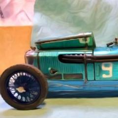
absmiami Posted July 19, 2021 Author Share Posted July 19, 2021 This is what it’s supposed to look like. Next is either the top gas tank and/or the steering link … Quote Link to comment Share on other sites More sharing options...
absmiami Posted July 19, 2021 Author Share Posted July 19, 2021 This picture is a screen grab from the Indy Museum Gurney 29 resto - the car is green because the Gurney 29 was repainted at some point following its retirement - this was corrected by the Museum during last year’s resto … Quote Link to comment Share on other sites More sharing options...
absmiami Posted July 25, 2021 Author Share Posted July 25, 2021 The AMT 29 kit has a scuttle tank part. Sort of …. More like an afterthought - maybe they neveR got a look at the tank - that’s not even close … Quote Link to comment Share on other sites More sharing options...
absmiami Posted July 25, 2021 Author Share Posted July 25, 2021 Using Renshape - it’s asymmetric because the radiator return pipe runs down the left side of the chassis on its way back to the radiator …. There is a channel on the bottom foR the steering wheel shaft … Quote Link to comment Share on other sites More sharing options...
absmiami Posted July 25, 2021 Author Share Posted July 25, 2021 Pegs in the front corners - .025 plastic rod - hope I can make this removable so I can show off the monocoque detail once it’s done …. The tank has a filler cap - but that won’t be made till the removable body work is done …. Quote Link to comment Share on other sites More sharing options...
absmiami Posted July 26, 2021 Author Share Posted July 26, 2021 The bulkhead at the back of the monocoque carries the suspension and cites the transaxle - the AMT kit part - In the second photo - is the guide …. Made from 2 sheets of .030 Evergreen sheet and some more bits for the extensions for the suspension links … Quote Link to comment Share on other sites More sharing options...
absmiami Posted July 31, 2021 Author Share Posted July 31, 2021 evergreen strip and rod and CA glue and epoxie for the rear engine mounts - with a little wiggle room - so the engine can be removed repeatedly without damage … Quote Link to comment Share on other sites More sharing options...
absmiami Posted July 31, 2021 Author Share Posted July 31, 2021 Then the front mounts - locate one at a time so that the pegs align … this is critical - most of the engine bay accessories can’t be made or located unless the engine is in the right place … need to leave just enough room for the Travel of the exhaust pipes back to the collectors - there is some guess work here …. Quote Link to comment Share on other sites More sharing options...
absmiami Posted August 4, 2021 Author Share Posted August 4, 2021 Coming soon to a building blog near you …. “The upper motor mount FROM HELL” … Quote Link to comment Share on other sites More sharing options...
absmiami Posted August 6, 2021 Author Share Posted August 6, 2021 The cylinder head engine mounts are riveted to the monocoque and have a low profile … Quote Link to comment Share on other sites More sharing options...
Recommended Posts
Join the conversation
You can post now and register later. If you have an account, sign in now to post with your account.
Note: Your post will require moderator approval before it will be visible.