Plastheniker
-
Posts
880 -
Joined
-
Last visited
Content Type
Profiles
Forums
Events
Gallery
Everything posted by Plastheniker
-
Excellent colour choices and fantastic finish!
-
Admittedly I am not the Porsche fan but this one looks really great!
-

Classic Japanese sports duo: Toyota 2000GT and Datsun 240ZG
Plastheniker replied to Matt Bacon's topic in Model Cars
Beautifully executed! Both kits that are not seen very often when finished. -
Hi, This is the old Italeri/Revell kit that seems to be OOP for quite a while. I built it 20 or 25 years ago. Built as a curbside model it is a really nice kit with only one major shortcoming: the unrealistically wide wheels. I reduced the width of the tyres and made real wire wheels. As far as I remember I detailed the interior, reworked the clumsy wipers and transferred the prancing horse and the chrome lettering on the boot lid from another kit. If you are interested in this classic Ferrari and if you can still obtain the kit I would really recommend it. A similar topic of mine: 1962 Ferrari GTO http://www.modelcarsmag.com/forums/index.php?showtopic=78461
-
Clifford, this is a really unique and spectacular model. Moreover the execution is immaculate. Simply fantastic!
-
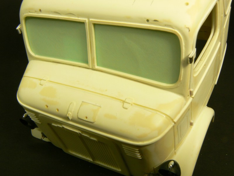
Curved Windscreens Curved windscreens imply a particular problem: Any kink or any undulation of the „glass“ will distort all reflections dramatically and spoil the appearance of the model. Therefore it is indispensable to make the curvature of the windscreen opening as clean as possible when preparing the cab. Prepare the cab as described in my first post. When removing resin around the windscreen with your rotary tool try to make the curvature as good as possible. Improve the curvature manually. Nevertheless the inner edges of the windscreen opening will be more or less a serpentine line. Cut a copy of the „cardboard window pane“ from thicker cardboard that is just flexible enough to follow the general curvature of the windscreen opening (but not the unintended small ups and downs of the serpentine line). From the inside lay a plane piece of thin styrene sheet (0.3mm or 0.5mm) onto the window opening (but do not glue it yet!). From the inside of the cab press the thick copy of the „cardboard window pane“ against the sheet. Fix the thick cardboard copy in this position provisionally but firmly. Now the styrene sheet should form a perfect curvature. Then glue sheet and fill the gaps between resin and sheet with super glue or plastic strips as usual. After drying restore the window opening and sand it flush. Now you should have a perfectly curved inner edge. The moment of truth comes when you insert the clear window pane. Check very carefully if there are any distorted reflections. If this is the case do not hesitate to touch up the curvature. Because the clear windscreen is cut from plane sheet its bottom edge (that is not fixed by a groove) refuses more or less to follow the curvature. Gluing this bottom edge into the curvature may be visible on the finished model – and this shall be avoided by my technique. As you probably recognized on my pictures I use the same order of assembly that we know from most styrene kits: I insert a sub-assembly (cab floor + interior lininings below the windows + fire wall + dashboard) into the glazed cab. Simply make the windscreen edge of the dashboard follow the curvature so snugly that it presses the bottom of the clear windscreen into the curvature. Good luck! *** Besides the Mack F and the GMC 9500 I used the technique on these models already shown in the MCM forum: All windows 1937 Mercedes-Benz L 10000 Scratchbuilt 1/24 http://www.modelcarsmag.com/forums/index.php?showtopic=75830 Scratch Built 1951 Büssing 12000 U13 6x4 Underfloor Engine Truck http://www.modelcarsmag.com/forums/index.php?showtopic=82042 1937 Bugatti Atlantic 57 S - Mother of all Sports Cars? http://www.modelcarsmag.com/forums/index.php?showtopic=80287 Side and rear windows 1950 Krupp Titan with Hanomag Trailer http://www.modelcarsmag.com/forums/index.php?showtopic=79775 1941 Chevrolet AK Pickup http://www.modelcarsmag.com/forums/index.php?showtopic=80531 Dodge L-700 with short flatbed trailer http://www.modelcarsmag.com/forums/index.php?showtopic=81522
-
John, I would really like to learn more about it. I will follow your next topics. Will we read more about it and see some results? AITM uses an almost ideal resin. It is lightweight, easy to work and easy to glue. On the other hand, however, it becomes extremely messy when you use a rotary tool. Without precautions you generate an incedible amount of tiny wheightless flakes that spread all over the room and adhere to everything (probably your lungs, too). I use this simple and inexpensive device that sucks in 99% of the flakes: From a 20 litre translucent plastic water canister I cut off the bottom third and dispose the rest. I cut a hole into the bottom of this canister third with the diameter of the tube of my vacuum cleaner. I fix the long side of the canister third onto my workbench provisionally with two clamps, insert the tube of the vacuum cleaner and put on a wide nozzle. Run the vacuum cleaner at maximum power and almost no flake will leave the canister. If you feel the necessity use a mask additionally.
-
Thanks for your further comments! I am really happy to see that there is still some interest in my very first topic here in the MCM Forum.
-
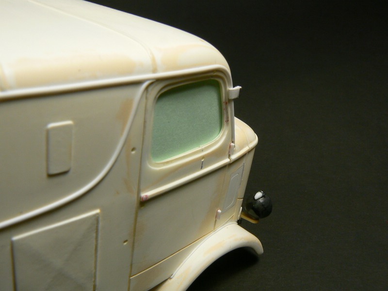
Thanks for the feedback! Plane windscreens Seldom there is enough space around the windscreen for doing exactly the same as on the side and rear windows. Mostly, however, the space between the windscreen and the side windows („A column“) is too limited for an interior lining - or it would simlpy look unrealistic. Then a special proceeding only for the windscreen is necessary: As already described in the first instalment prepare the cab also around the windscreen opening, and cut a clear and a cardboard windscreen. Again fix the cardboard windscreen temporarily (e. g. with tape ) onto the windscreen opening in exactly that position the later windscreen shall have. When cutting the two interior linings for the side windows leave a small gap (=groove) just wide enough for the cardboard windscreen. These two gaps will hold the two side ends of the windscreen. Next cut a headliner and again leave a small gap just wide enough for the cardboard window pane. The cardboard windscreen makes all three gaps form one single groove. Glue interior linings and headliner in place. From the bottom you can now insert and remove the clear windscreen as you like. When assembling the cab after painting secure the invisible long bottom end with glue if necessary. On these pictures the clear windscreen is replaced by green paper for better visibility. To be continued as soon as possible Again, please give me a feedback if everything in this second instalment is understandable so far. If necessary tell me which further explanation should be given. My following description for curved windscreens requires understanding this second post completely. Thanks!

-
Freightliner FLC120 winch truck
Plastheniker replied to onescalenova's topic in Model Trucks: Big Rigs and Heavy Equipment
Gérard, this is exactly what a workhorse should look like! -
International Lonestar!
Plastheniker replied to Chris guthro's topic in Model Trucks: Big Rigs and Heavy Equipment
Chris, this is a really unusual colour combination that works on the model! Excellent execution. -
Douglas, this is certailnly not OOB! The crew cab was an excellent idea and also excellently executed!
-
JT, nice and unusual as always!
-
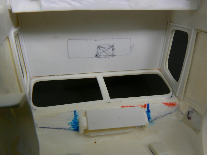
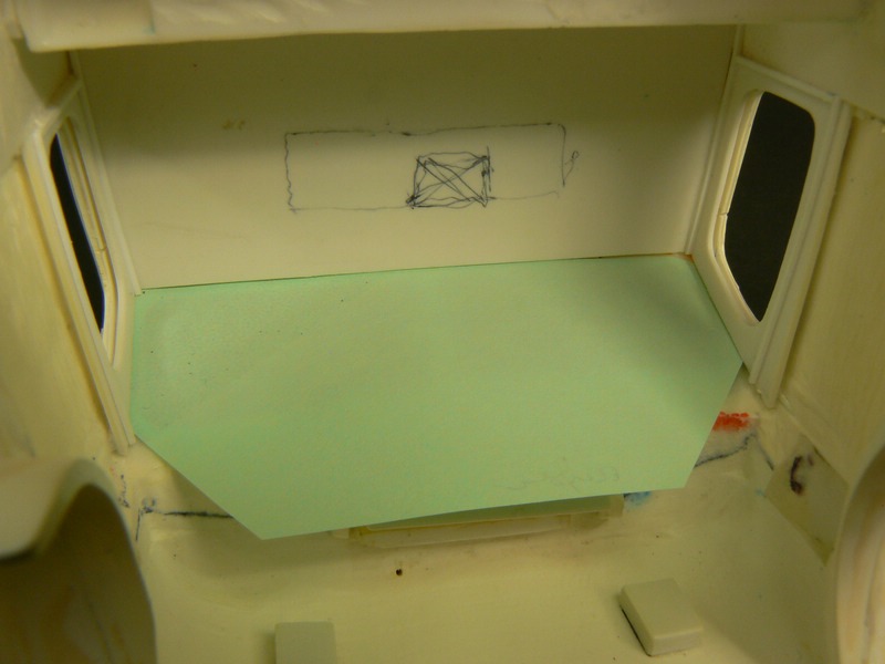
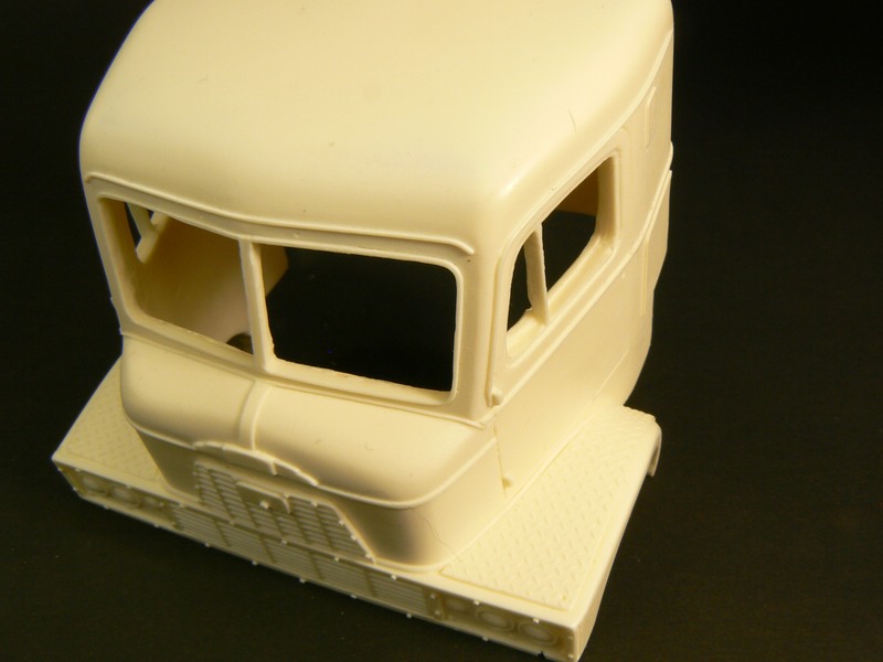
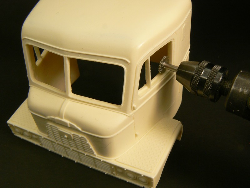
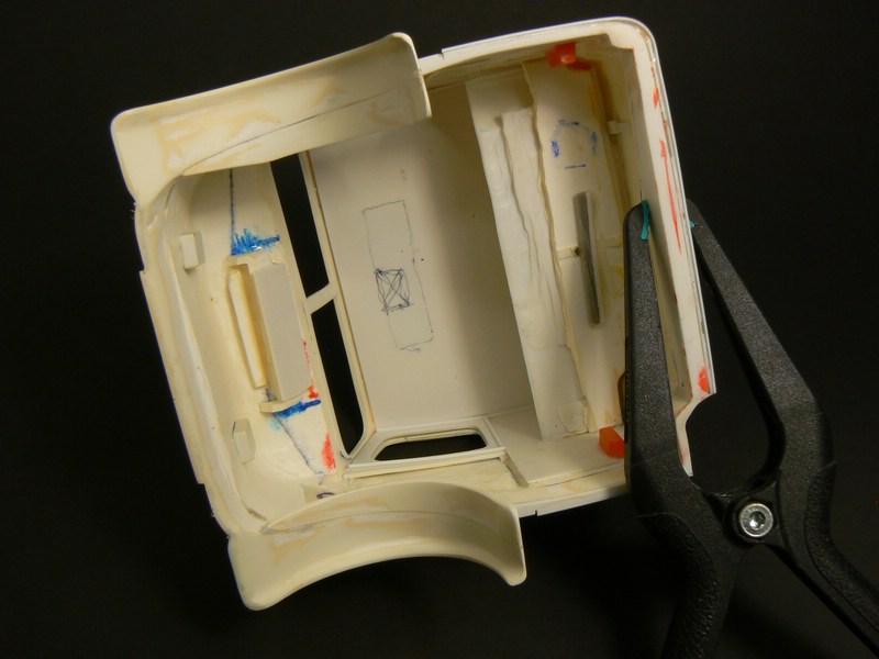
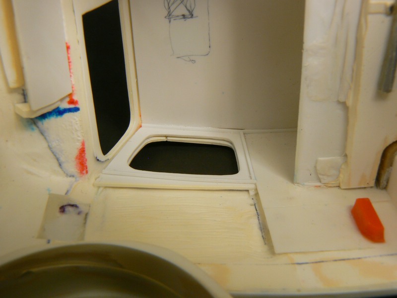
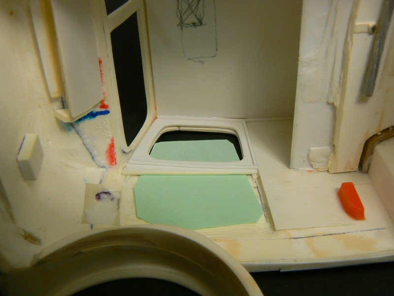
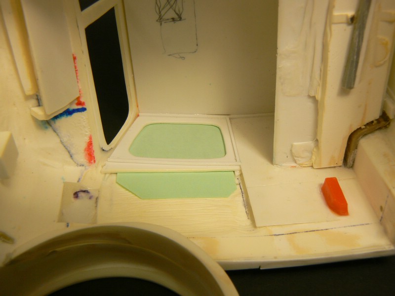
Fixing car windows without glue This technique, though rather time-consuming, is very useful for resin cabs and for scratch built truck cabs. Mutatis mutandis it can be used also for styrene or diecast truck/car kits/models/conversions if the kit glass is poor or doesn't fit if you want to make sure that no glue is visible on the glass if you want to eliminate the risk that if touching the finished model carelessly the glass falls into the car interior. The technique is appropriate only for advanced or expert modelers. I am going to explain it showing AITM resin cabs. The basic idea The basic idea is similar to framing a picture. A picture is framed by gluing together a “U” from 3 grooved wood strips. The picture is inserted into the groove of this “U” and a fourth strip closes the “U” and fixes the picture. Simply replace “picture” by “clear sheet”. Because nobody is able to mill a microscopic groove into a model car, you have to build a groove. Preparing the resin cab A typical AITM cab looks like this: First you have to remove enough resin around all windows that the following steps are possible. This is messy and time-consuming. Mostly a rotary tool with various steel cutters can be used. Start at the window openings and then continue from the inside. When you have removed enough resin the inner edges of the window openings will be varying and not straight. From the inside glue a plane piece of thin sheet (0.3mm or 0.5mm) onto the window opening. Fill the gaps between resin and sheet with super glue or plastic strips. After drying restore the window opening and sand it flush. Now you should have a perfect and plane(!) inner edge. Plane side and rear windows From clear sheet (max. 0.4mm thick) cut a “window pane” a bit wider but much higher than the window opening. Mark on a piece of tape what is right/left and top/bottom. Cut an identical piece of cardboard or other waste that is slightly thicker ( appr. +0.3 mm). Fix it temporarily (e. g. with tape ) onto the window opening in exactly that position the later window pane shall have. Glue 3 styrene strips to the upper edge and the side edges of the "cardboard window pane". These strips must be slightly thicker than the cardboard. Now the cardboard cannot move to three sides. Remove the cardboard. From 1mm styrene sheet cut a fitting cab interior lining with matching window opening. Glue it onto the 3 styrene strips. From the open bottom you can now insert and remove the clear window pane as you like. When assembling the cab after painting secure the invisible long bottom end with glue if necessary. On these pictures the clear window pane is replaced by green paper for better visibility. Do the same with all other side and rear windows. To be continued as soon as possible Please give me a feedback if everything is understandable so far. If necessary tell me which further explanation should be given. My following description for windscreens requires understanding this first post completely. Thanks!
-
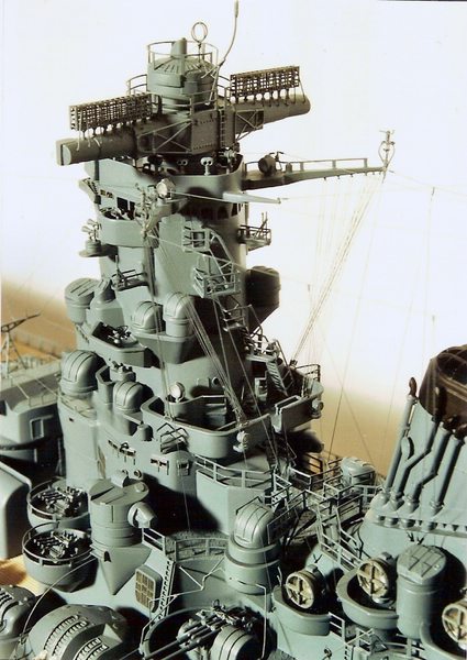
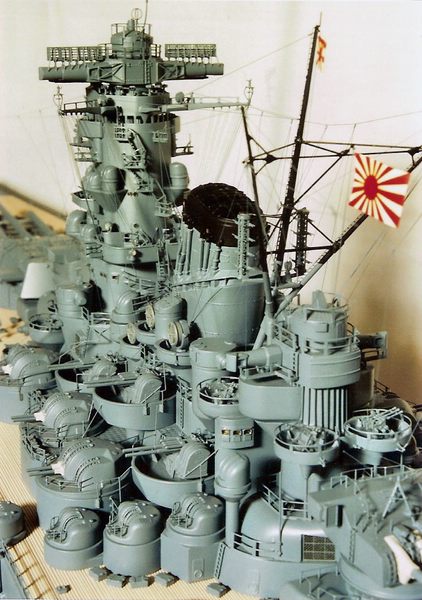
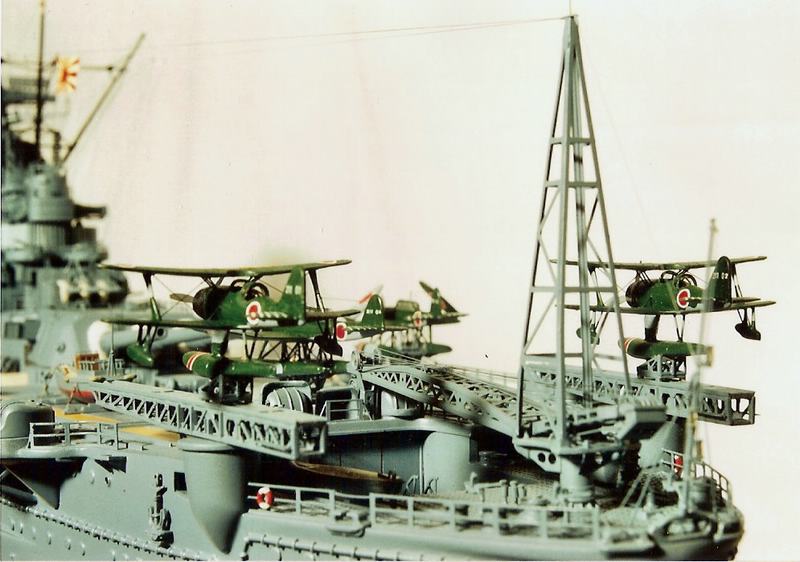
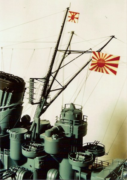
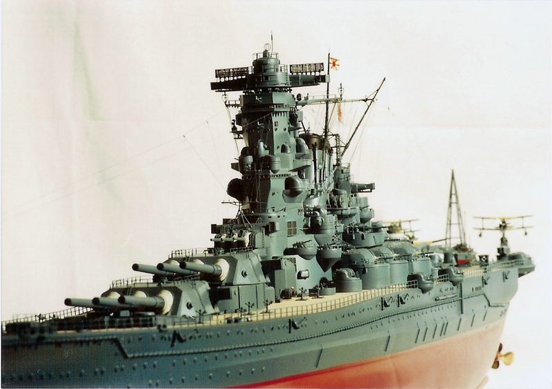
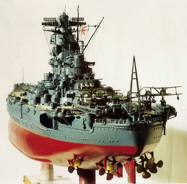
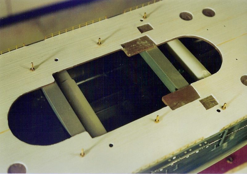
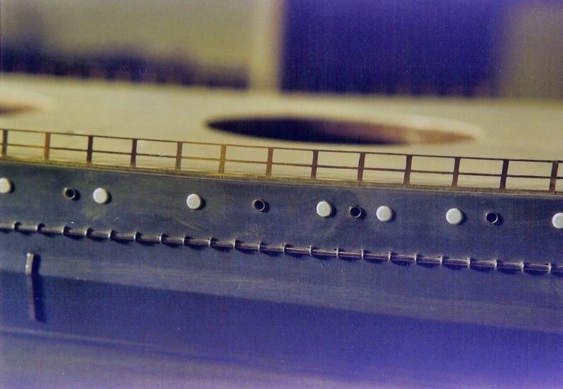
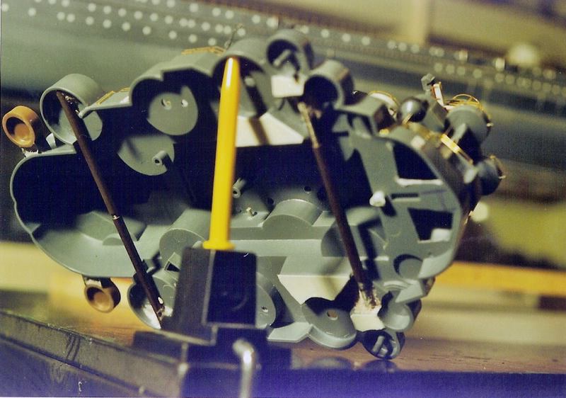
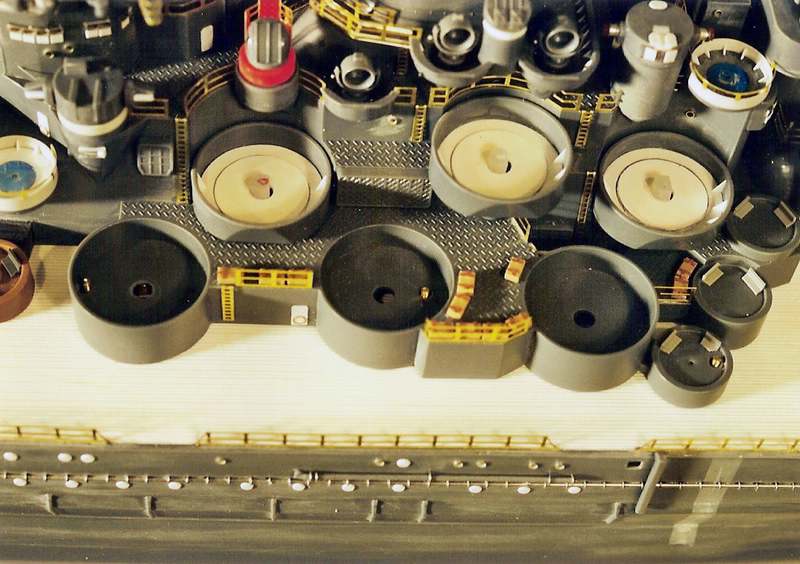
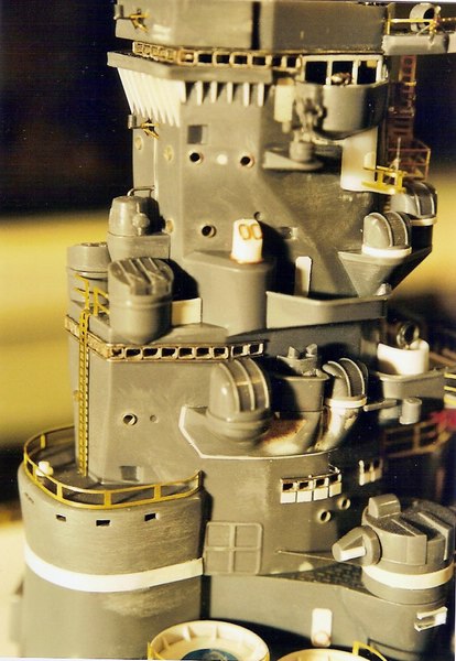
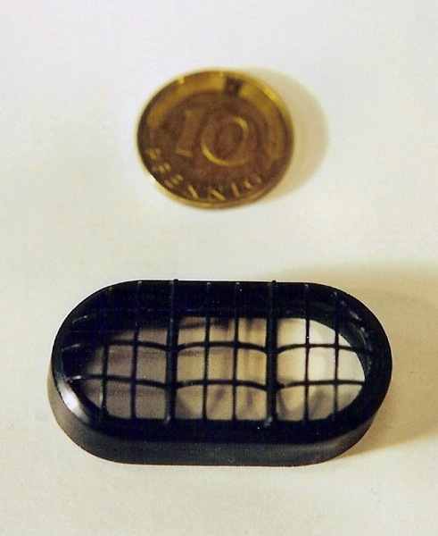
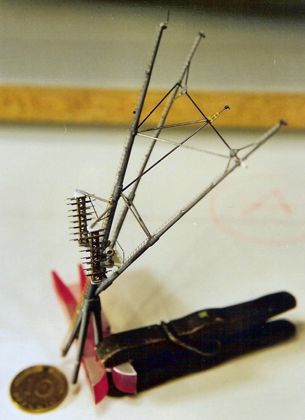
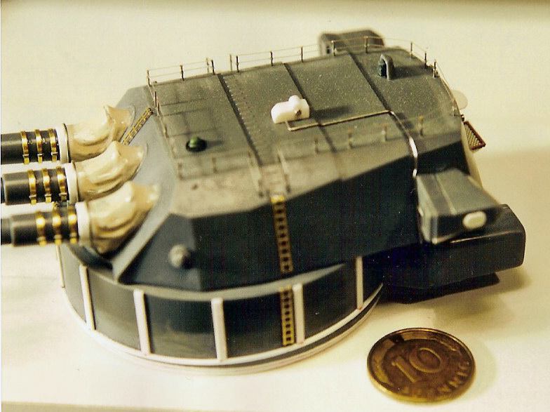
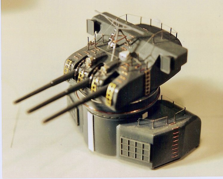
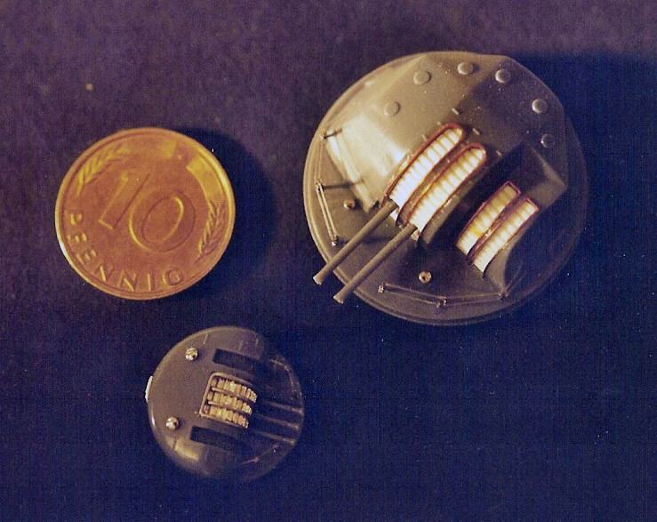
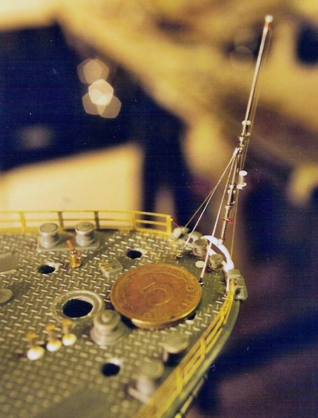
Thanks for the comments! I found some old WIP paper pictures made with a 35mm SLR and scanned them. Though they are more than 20 years old the scans didn't turn out that bad. These first 6 pictures show the finished ship before I added the final display stand and before I put her into the display case. Due to the different illumination and without any glass reflections further details become visible. The following 11 pictures show some WIP sub-assemblies. Probably the give a rough impression of a few problems and some detail work. 1: I aligned the warped sides of the hull with telescoping plastic tubes. The warped „wood“ deck of the kit (brown) was aligned with massive metal square rods and then covered by a scribed new deck. Since the main superstructure part (shown on pictures #3&4) was also badly warped I decided to screw it onto studs. You see some of the brass studs protrude. 2: The port-holes were poorly moulded and mostly placed incorrectly. I replaced them (if not blanked off) by wire end ferrules. The moulding of the degaussing cable was conspiciousy varying. I replicated it with soldering wire. 3: I aligned the warped main superstructure part with treaded rods and treaded sleeves fixed to the bottom. 4: A detail shot of the superstructure. The brass studs protrude into the bases of the 12.7mm AA turrets. These turrets would conceal studs and tightened nuts. 5: A detail shot of the tower bridge with some corrections. 6: The massive, completely closed funnel hood after reworking. 7: The tripoid mast of the kit didn't show the 1944 refit. Converting it I used universal PE frets and telescoping hypodermic needles. 8: A modified 46cm gun turret and barbette. The light railings on top are made of thin hypodermic needles and nylon monofilament. 9: A modified 15.5cm gun and barbette. 10: A modified 12.7cm AA gun turret and a modified triple 25mm AA gun with shield (rather small even in 1/200) 11: New ensign staff, towing fairlead, and further details hypodermic needles and nylon monofilament.
-
When I joined the MCM Forum nine months ago I concluded my introduction: „... I join this forum as some kind of refugee from quarrelsome forum users in Germany. Although they are a very small minority it is almost impossible to dodge their attempts of starting a vendetta. I do hope the atmosphere here will be peaceful and really focused on modelling.“ Therefore I ignored Anthony's last post. It was obviously unfounded and not model-related. As my a. m. quotation says I agree totally. In his posts #17 and #21 Harry said everything necessary. He made clear that there is neither censorship nor self-censorship in this forum. Nevertheless I am grateful for all further supporting posts because they showed me that obviously this is the oppinion of the moderating team a n d the forum members as well. I am going to return to my workbench now. There is too much work waiting, and life is too short for quarrelling.
-
Ben, I used the AMT Cruise-Liner as a donor kit. Though I love the old AMT trucks I must say that the fit of the chassis parts was not very good and that the right position of parts was often vague. The same is true for the R985ST. The (originally Ertl) DM600/DM800 are much better .But as far as I know all these kits are OOP and thus extremely expensive. As far as I know from German forums all newer Italeri kits have a simple generic chassis. Probably an older Italeri kit is easier to convert.
-
Jesse, Michael, I will try to explain the technique. While the technique itself is rather simple the explanation is rather difficult (I did it in a German forum probably without much success). This is why a picture or drawing will be necessary. Therefore please give me a little time.
-
Thanks for your replies! Harry, thanks for your support! Anthony, reading your posts for the first time I thought After reading them again,however, it seems to me that they were simply insufficiently thought out. Probably we all agree that modeling forums are not made for promoting sales of manufacturers but for supplying own and substantial information in order to help other modelers to choose modeling products. In the early days of modeling forums I used to post my pictures without further information. Among these models was an extensively improved, originally extremely poor but expensive kit. Some time later a forum member posted that he bought the same kit and was annoyed to see that the box content had little to do with my model. He reproached me with wasting his money by being too lazy for giving essential information. Therefore I never post pictures without mentioning all major shortcomings and everything that is not OOB. Holding back such information – t h i s is unjust. If your oppinion remains different – it is at your discretion to ignore my future topics. BTW reading obviates writing sometimes. My post #43 in the mentioned GMC topic says: Admittedly the AITM cabs have their shortcomings, and it takes a lot of effort, and it requires some skills to achieve a nice result. Nevertheless for the true vintage truck enthusiast the effort is really worth, so I would like to encourage every inclined modeler.
-
Hi, The F-series was a big sales success in America. Besides this the F-models were the only American trucks that ever reached Europe in more than imperceptible numbers. Nevertheless there was never any styrene kit. There were only two resin cabs, namely an old one by AIM/AITM and a newer one by KFS. Regarding quality the pricey KFS cab is light-years ahead but it replicates a (in my oppinion less attractive) late model sleeper cab and besides this it is OOP for quite a while. Most problems of the AITM Mack F-cab are identical with those of my AITM 1970 GMC 9500 shown earlier. The worst problem that spoils almost any finished AITM F-series cab shown online is the grille. It is cast as an integral part of the cab. The „gaps“ between the grille bars are filled with resin, and the grille bars are very flat. It is impossible to make this grille look realistic. This is why you find a lot of pictures taken from an angle where the grille is more or less concealed. For an acceptable model it was indispensable to build a realistic new grille. As said in the GMC contribution a striking blemish of many finished AITM cabs is the use of a bed of white glue for fixing the cab windows as AITM recommends. Firstly it is almost impossible to cut out the "glass" so accurately that it fits without any gap and without any kink, secondly the required large amount of white glue dries as a visible white ring around the windows. Since the F-cab has very large and curved windscreens this becomes even more obvious. Again I used my technique of fixing the „glass“ without any glue. The pictures show that there is neither any gap between "glass" and window frame nor any kink in the "glass". Casting quality was partially very poor. F. e. there were varying edges between raised and recessed areas of the rear panel, so I had to cut out and rebuild the recessed areas. The resin thickness was extreme and had to be reduced drastically to make the cab look realistic. Afterwards the supplied (very simple) interior was much too small, so I had to build a complete new interior. All supplied accessory parts were unusuable. I built them new or took them from my spares box. Nevertheless the F-cab (as the GMC 9500) is a time-consuming but very rewarding project. A similar topic of mine: 1970 GMC 9500 Short Hood (AITM) with Tube Trailer (Scratch Built) http://www.modelcarsmag.com/forums/index.php?showtopic=74735
-
Thanks a lot for the further feedback! As already announced in this thread my next model in the Big Rigs sub-forum will be a 1969 Mack F daycab (also AITM). I hope you will be interested again.
-
Looks really good and more interesting than the sleeper. What about some larger pictures of the tractor?
-
FORD 1941 COE TANKER
Plastheniker replied to CUSTOMBOY's topic in Model Trucks: Big Rigs and Heavy Equipment
An unusual and well-made model, would be really interesting to see it in a factory-fresh paintwork,too. -
Peterbilt 362 Hay Truck 1:22
Plastheniker replied to Bricksonwheels's topic in Model Trucks: Big Rigs and Heavy Equipment
Dennis, usually I don't follow WIP threads, but I really wonder what the used Lego parts look like and how you proceed. Since I suppose that I am not the only one, so what about a pictorial WIP contribution? I followed the link to your homepage - simply stunning! BTW how do you keep that cat from your models? -
Thanks for the further comment, much appreciated!