Chariots of Fire
-
Posts
2,781 -
Joined
-
Last visited
Content Type
Profiles
Forums
Events
Gallery
Everything posted by Chariots of Fire
-

2-part tires on amt trailers?
Chariots of Fire replied to 1959scudetto's topic in General Automotive Talk (Trucks and Cars)
Ever have any of those early tires actually sweat? I had a few that did and left a wet surface. There was also a time when they put in real soft rubber tires in some of the truck kits. They were fine until they started to rot, just like real ones and then they just fell apart. -
1952 F-7 Ford
Chariots of Fire replied to Chariots of Fire's topic in WIP: Model Trucks: Big Rigs and Heavy Equipment
Got a bit more done on the F-7. The brush bars have been roughed out and attached to the bottom bumper. They are still removeable with the bumper. The vertical piece to the rear of the tire is simply pinned on the bottom but is not secured yet making it possible to take everything off for final cleanup and painting. I have to drill some holes in the fenders for bracing. That should be fun! -
1952 F-7 Ford
Chariots of Fire replied to Chariots of Fire's topic in WIP: Model Trucks: Big Rigs and Heavy Equipment
Thanks, Charlie. Yes I will be at NNL East arriving late Friday afternoon Lord willing. -
Just need to know where to send them
-
Terry: Do have the Mack emblem for the sides of the cab? If not I can send you some.
-
1952 F-7 Ford
Chariots of Fire replied to Chariots of Fire's topic in WIP: Model Trucks: Big Rigs and Heavy Equipment
The cab is now secured to the frame. The engine wiring has been completed and now it's on to fabricating the brush bars that go around the front and sides to the body. The hinges are now separated and the connecting stainless steel wire was snipped and secured to each hinge. Worked out pretty well.
-
1952 F-7 Ford
Chariots of Fire replied to Chariots of Fire's topic in WIP: Model Trucks: Big Rigs and Heavy Equipment
try one more time! Hey it worked!
-
1952 F-7 Ford
Chariots of Fire replied to Chariots of Fire's topic in WIP: Model Trucks: Big Rigs and Heavy Equipment
try this posting 13658779/001-vi.jpg Forget it! I just made up a new Fotki album and are having a bit of trouble figuring out how to transfer photos here. Photobucket is just too slow. -
That is part of what I have for reference info as well. Autocar A64B kit fenders are pretty close to the fenders used on these trucks. I turned mine around and did a bit of modification on them so I could attach them to the frame. The ones on the model are resin castings.
-
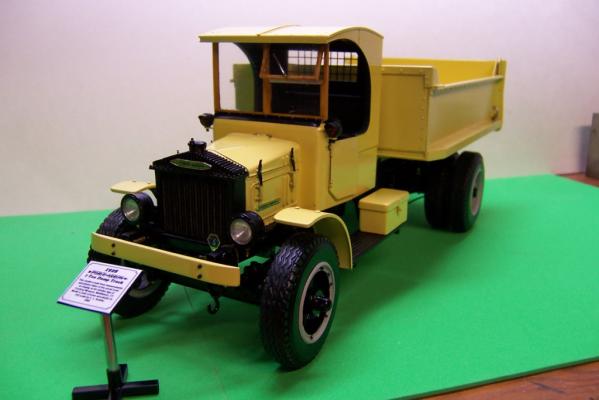
Terry: Here are a couple of photos of the Mack AP. Looks like I used some of the same reference material that I see in your photos.
-
Making Brass Hinges for an F-7 Ford
Chariots of Fire replied to Chariots of Fire's topic in Tips, Tricks, and Tutorials
Here is Part 3. I wish I had taken photos of the hinges before they were mounted but at the time I did not expect to be writing a tutorial on the process. Would have been nice for the photo documentation of the build as well. But...I did not. So what is ahead is what I have. -
I'm watching this one with interest. A couple of years back I did a Mack AP like the kind they used to construct Boulder (Hoover) Dam. Lots of interesting details on those old trucks like the springs inside the frame that acted as slack adjusters so stones would not bind up the chain drive. Nice work on this rig!
-
Making Brass Hinges for an F-7 Ford
Chariots of Fire replied to Chariots of Fire's topic in Tips, Tricks, and Tutorials
Here is part two of the hinge tutorial. I'll finish it off with some tips on how it all goes together on the cab and doors in Part 3. -
1952 F-7 Ford
Chariots of Fire replied to Chariots of Fire's topic in WIP: Model Trucks: Big Rigs and Heavy Equipment
Today was paint day! Sometimes you just get to the point that there's no more fooling around and out comes the paint can. With this part concluded I can concentrate now on the interior of the cab, get the dash done up and get the pedals, shift, 4wd levers, low range lever and seat installed. Then it's on to the body and some details for the pump, hose reels and other firefighting stuff. Once everything is in place the stainless pin that holds the door hinges in place will be cut and secured to each hinge. -
1960's Mack B61 wrecker
Chariots of Fire replied to greymack's topic in WIP: Model Trucks: Big Rigs and Heavy Equipment
George: Would you be offended at some constructive criticism of your project? I think I see something that might help but wanted your permission to speak of it first. -
ford c600
Chariots of Fire replied to Ken Gilkeson's topic in Model Trucks: Big Rigs and Heavy Equipment
Those are really nice. Like the black over blue one especially! -
1952 F-7 Ford
Chariots of Fire replied to Chariots of Fire's topic in WIP: Model Trucks: Big Rigs and Heavy Equipment
If you check out the Tips, Tricks and Tutorial section below you will see the first of two postings on how I did the hinges. In a nutshell the hinges are set into notches made in the edge of the door. After the door is notched, each hinge is pinned to the door using a piece of brass wire. The wire is then filed flush with the top of the flat stock that rests against the edge of the door. Superglue holds it all together. One thing I have noticed is that if the brass is dirty, the glue will not adhere well. An option would be to use two part resin as an adhesive but I like the glue. Another thing on cutting out the doors is that you loose a little material in the process so it is necessary to add some strip stock around portions of the edge of the door to close up the opening. Doing that along the edge where the hinges are seals the brass hinge behind the strip stock as well. Trim the stock to match the shape and thickness of the door. -
Several of you have asked about how I made the brass hinges for the F-7 Ford that I am building. See the post in the workshop section to see the build. Here is the first of two tutorials on how I did the hinges. The second portion will cover how I did that hinge half that is attached to the door jam. As I posted in the Workshop section, when the doors are scribed for opening, material is lost between the cab and the door. After the full hinges are made and in place it will be obvious that there are places around the door opening that either need to be sanded down or filled in so that the door closes well and the space between door and cab is uniform. When filling, use a small piece of strip stock, say 0.010 thickness and glue it to the door edge. After the glue sets, trim the edge of the strip stock so that it follows the shape of the door edges. Don't forget to use a bit of filler as necessary to that the edge of the strip doesn't show when the door is painted. If you use a piece along the edge of the door that has the hinges, you can cover the brass hinges with the strip and that helps to lock them even better to the door.
-
1952 F-7 Ford
Chariots of Fire replied to Chariots of Fire's topic in WIP: Model Trucks: Big Rigs and Heavy Equipment
HI, Mike: Was out your way yesterday in Chicopee to the Wings and Wheels show. Had a good time. I used superglue to attach the hinges but did some other things as well. When I get a chance to post the tutorial on how they were made I think it will be clear as to how it can be done. -
1952 F-7 Ford
Chariots of Fire replied to Chariots of Fire's topic in WIP: Model Trucks: Big Rigs and Heavy Equipment
Hi, Aaron. About the 8 lug wheels: I just sanded of the 10 lugs smooth. I used a circle template to locate 4 lug points as a square and then filled in between with 4 more. I used some plastruct hexagonal rod cut in pieces to glue on as new lugs. I'll have to draw something up so you can see the process. Will try and come up with something. -
1952 F-7 Ford
Chariots of Fire replied to Chariots of Fire's topic in WIP: Model Trucks: Big Rigs and Heavy Equipment
The last couple of days have been intense making small brass hinges for the doors so that they could open. 0.018" brass tubing and stainless steel wire that fits neatly inside was used along with some C section brass. Now the doors open and close pretty well. I opened the doors by scribing the outline with the back of an Xacto knife. The engine is now installed on the painted chassis. The photo of the real truck shows how far there is still to go on the model. One thing at a time... -
1952 F-7 Ford
Chariots of Fire replied to Chariots of Fire's topic in WIP: Model Trucks: Big Rigs and Heavy Equipment
Hi, Frank. I did answer your post. But to reiterate it came from Ken Kitchen of Colorado Springs, CO. He does resin castings under the name of Kitchen Table Resins. I did not see your pm. Sorry. -
If it's a raised mark, sand or grind it away. If it is depressed, use some filler like Squadron or Tamiya and then sand it smooth.
-
1952 F-7 Ford
Chariots of Fire replied to Chariots of Fire's topic in WIP: Model Trucks: Big Rigs and Heavy Equipment
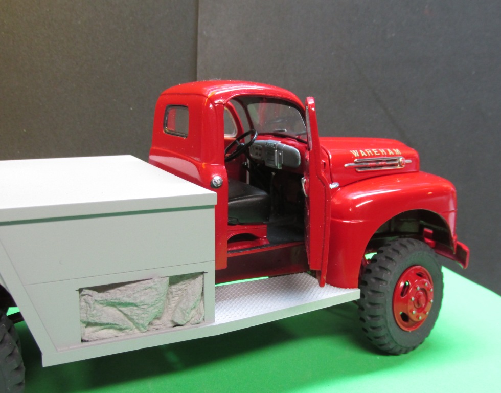
work continues on the F-7. Tonite the headlight trim rings were turned on my lathe and some lenses were taken from the parts box. The front bumper is set where it should be but it will need some additional work on the ends. The body has 3 compartments; one on each side and one in the rear. The doors have hinges of brass tubing and stainless steel. The door cutouts will have some of Don Mills slam locks. The lone bumper in front of the truck is the beginning of the top brush bar that wraps around the front and sides. The drive shafts have been finished and painted for installation once the frame is done. I set some double sided tape on the hood sides to temporarily see where the hood trim will sit. -
1952 F-7 Ford
Chariots of Fire replied to Chariots of Fire's topic in WIP: Model Trucks: Big Rigs and Heavy Equipment
A bit more done on the F-7. The plastic driveshafts in most truck kits just don't look right so I tend to make my own. Using some brass square stock, brass tubing and the the brass rod X's that I showed previously, the driveshafts were made up. They are done in sections that slip together so it's easy to install the ends into the axle pumkins and transfer case.