Chariots of Fire
-
Posts
2,777 -
Joined
-
Last visited
Content Type
Profiles
Forums
Events
Gallery
Everything posted by Chariots of Fire
-

Driveshaft for an easier installation
Chariots of Fire replied to bobss396's topic in Tips, Tricks, and Tutorials
I do exactly the same thing but with 3D printed U-joints and brass tubing. Looks like we are just about on the same page!👍😎 -
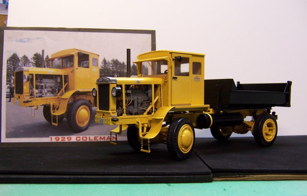
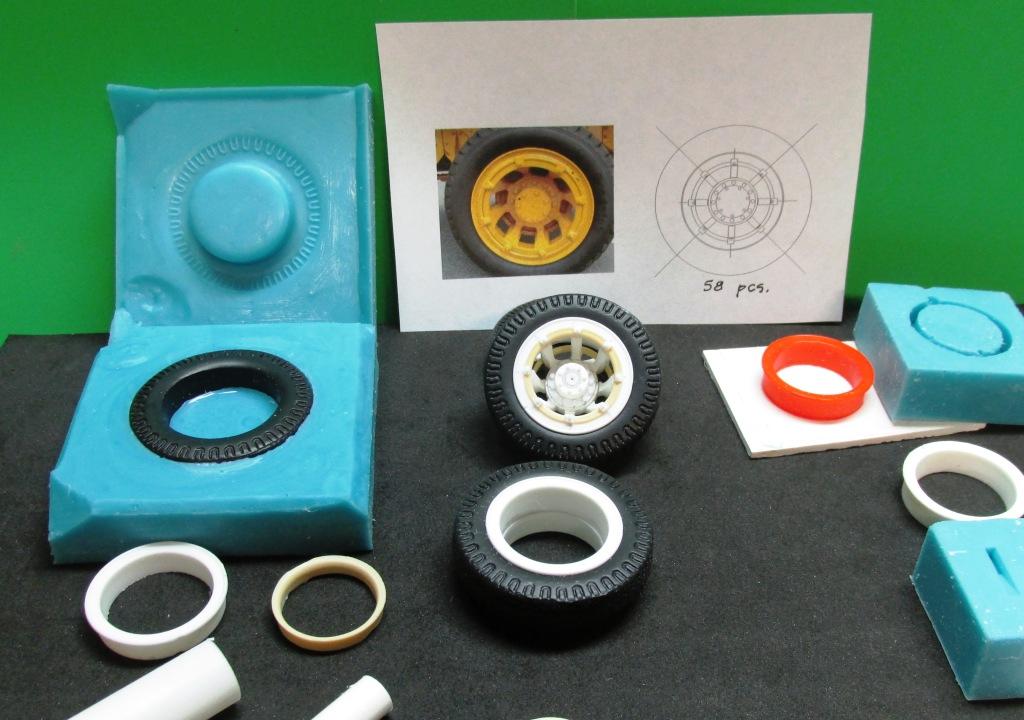
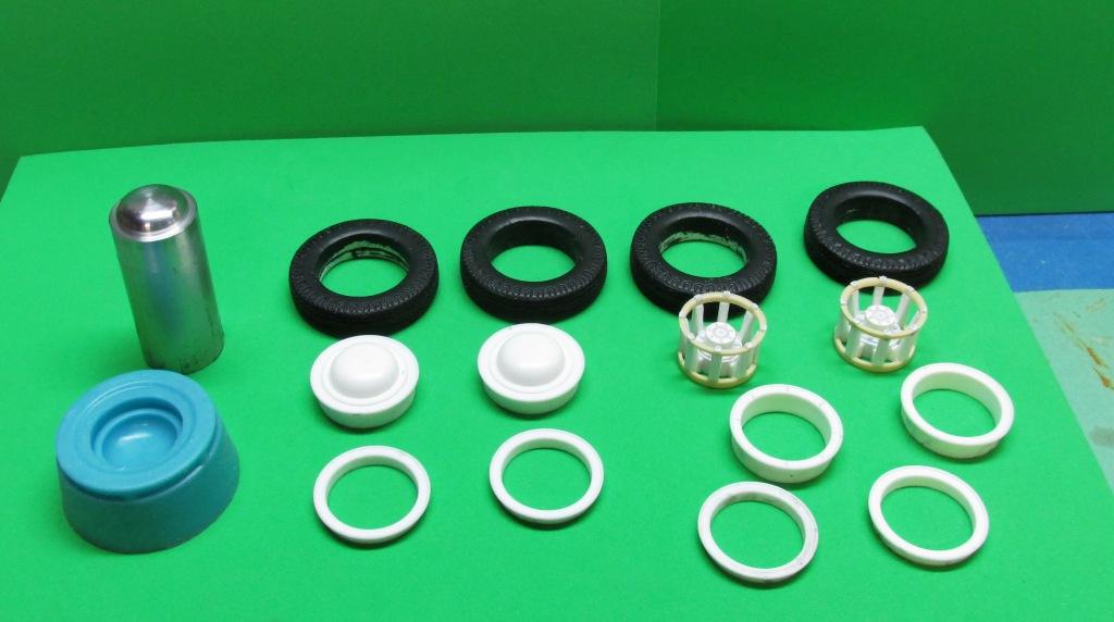
Dominick inquired as to how I make tires for my models. Below is one mold that was done for the tires used on the 1929 Coleman. The description of how to do it is below the photo. In this case front and rear tires are identical so only one mold was necessary. The tire mold is in the left side of the above photo. I use mold rubber that is sold by MicroMark. It is opaque and has excellent molding qualities and picks up all details nicely. 1. Start with building a box to contain the mold rubber. I use craft board but any stiff card will do. Leave enough room completely around the tire. Glue up 4 sides and the bottom of the mold box. It needs to be high enough that will be mold rubber under the tire as well as above it. A glue gun makes quick work of building up the box and it does not need to be perfect. 2. Mix up the two part mold rubber and pour it into the bottom of the mold box about 1/3 of the height of the box and let it cure. 3. Mix up another batch of rubber and pour a very small amount over the surface of the previously cured rubber. Cover the face down side of the tire with a small amount of rubber so that it completely covers the bottom sidewall and all of the detail of the tire surface. Place the tire in the mold and gently swish it around to make sure there are no air bubbles under it. Use a weight to hold the tire in place. You don't want it to float up after the next step. 4. Pour the rest of the second batch of rubber around the tire and let it cover the entire area of the box. Continue to carefully pour the rubber around the tire until you reach the upper surface of the sidewall. Do not let the mold rubber get on the sidewall. Walk away from everything at this point and let the second pour cure completely. If it has cured completely, it will not feel sticky when you touch it. Note that there is no mold rubber inside the tire other than the thin veneer that was put there in step 3. 5. With a sharp Xacto knife cut notches in the corners of the mold box and remove a small section of cured rubber. The photo above shows where I cut away to corners and along one side. 6. This next step is important. Spray the entire interior of the mold box and the surface of the tire with mold release. You can use petroleum jelly or a spray, which is what I prefer. IF you forget to do this you won't be able to separate the two mold halves. 7. Mix the final batch of mold rubber and pour it into the mold making sure to cover all exposed surfaces of the tire. Make sure there are no air bubbles. Continue to pour until you have completely covered the tire and bring the rubber to the top of the mold box. Let it cure completely. 8. After the rubber is cured, break away the sides of the mold box and remove them. Do the same for the bottom. Then separate the two parts of the mold. Remove the tire master and you will be ready to pour two part resin into the mold and make a tire. Note that I did not include an air release for the resin to escape. 9. Fill both sections of the mold with resin and check for air pockets. Make sure the resin is all around the face of the mold so that the tire tread is covered. Let the two sections of the mold with the resin gel just a little and quickly flip one half of the mold onto the other. Square it up using the notches as a guide. After the resin is cured, break the mold apart and remove the new casting. There should be more than enough resin so that the excess squishes out the sides of the mold. Below are the tires made from the mold for the Coleman. They were white when they were removed from the mold. Flat black was used to paint them. Hope this helps in how to make tires!😎

- 2 replies
-
- 11
-

-

-
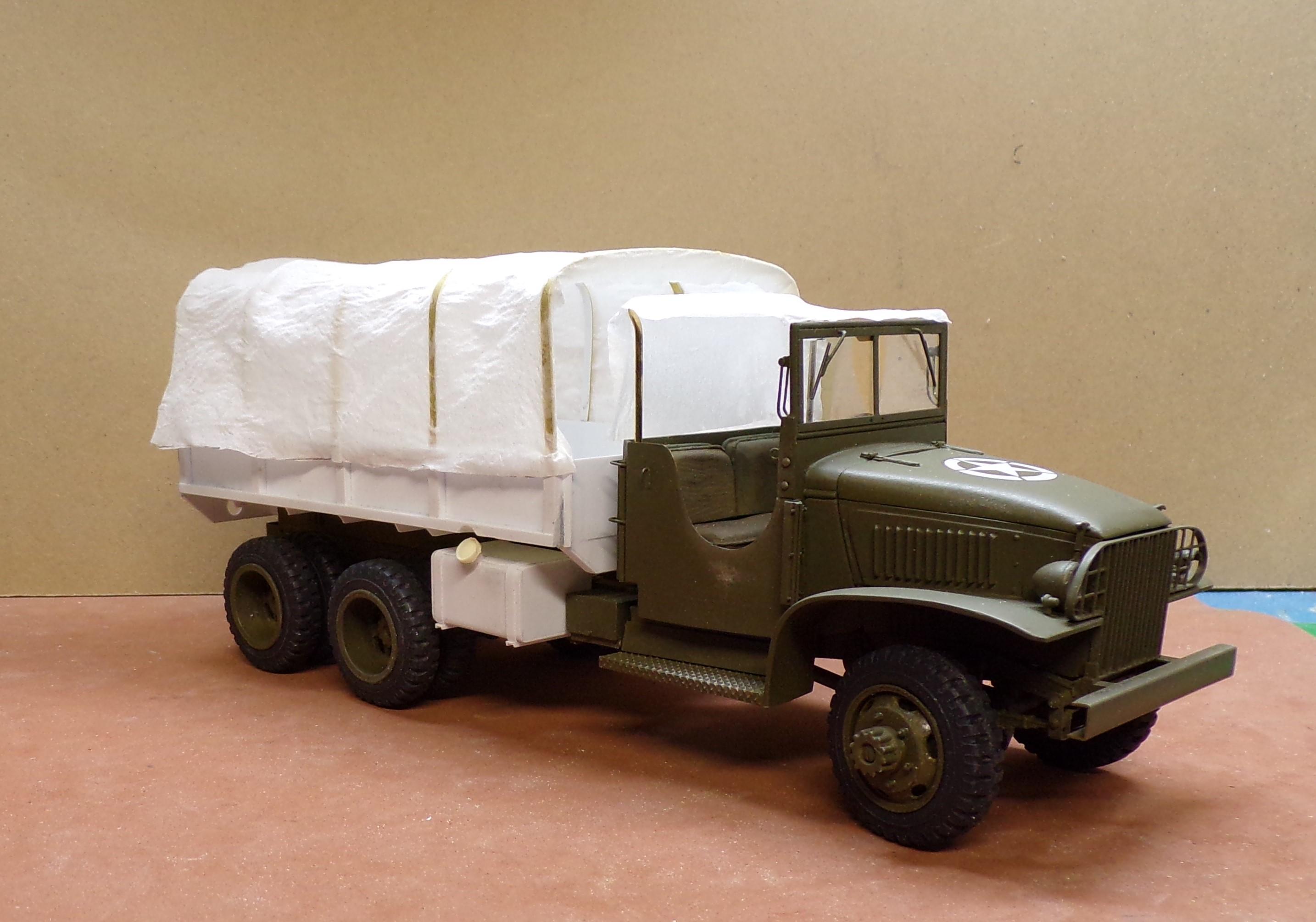
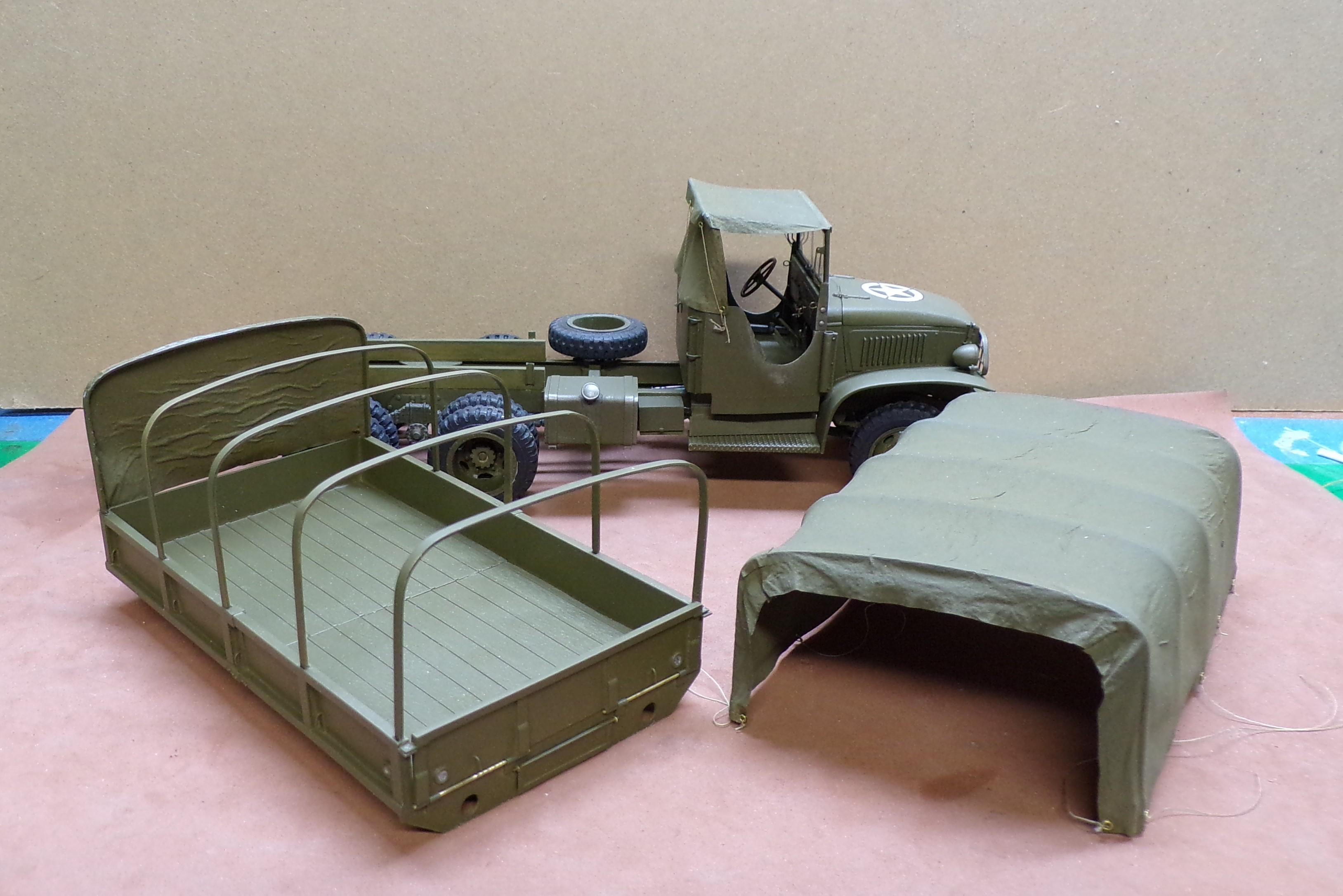
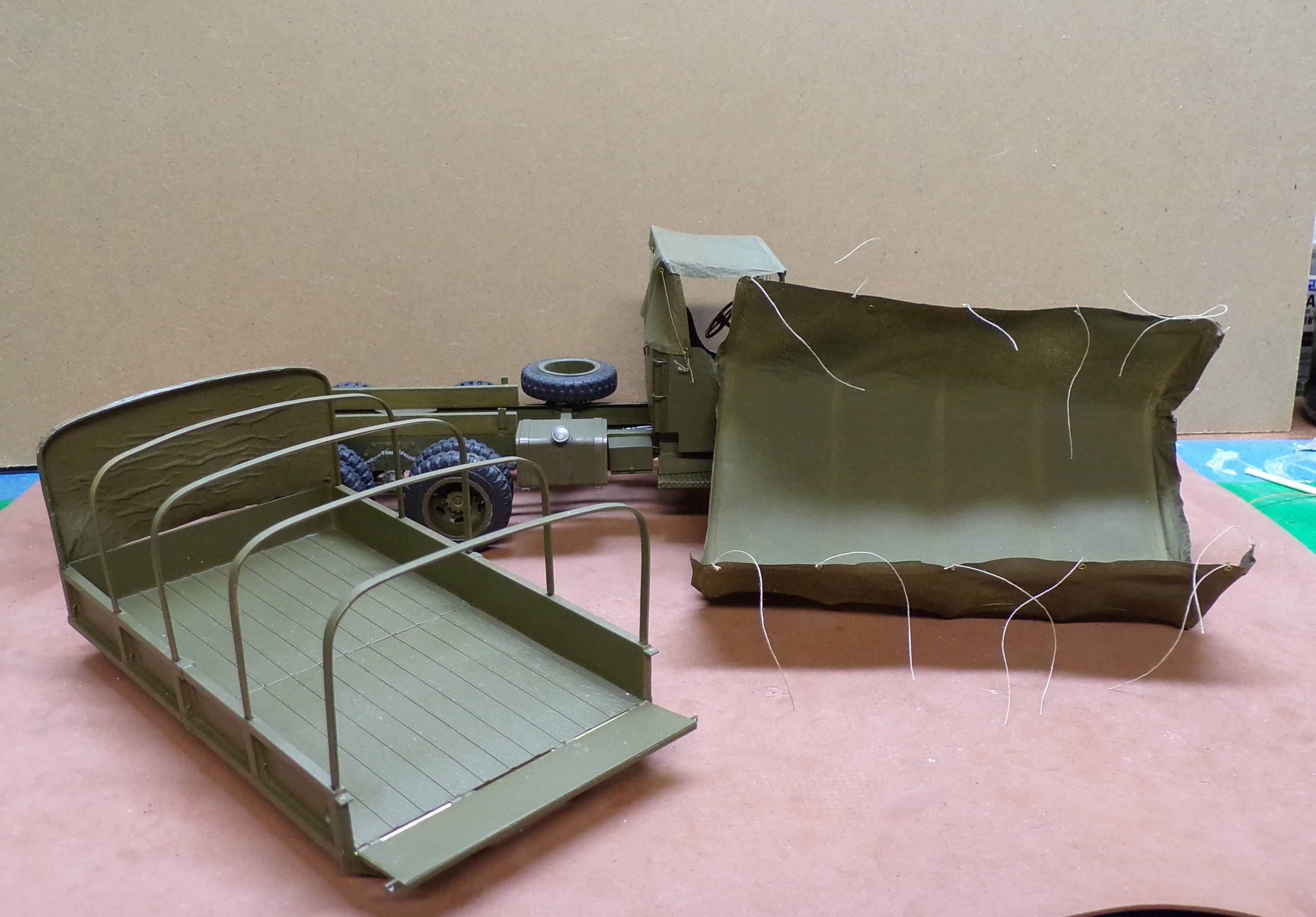
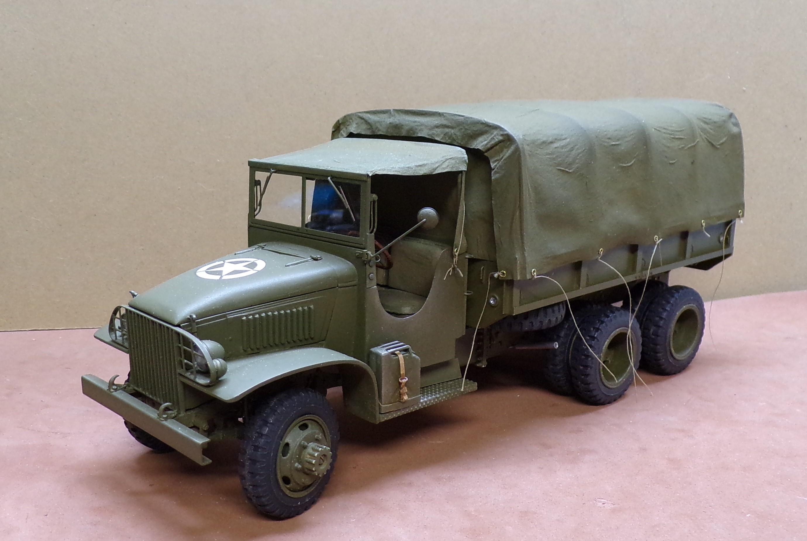
Getting back to tarps,,AHEM!! I made several canvas tops for my militay builds using regular two ply plain facial tissue. I cut to rough shape, drape them over whatever form I'm using and paint the whole surface with a 50/50 mixture of white glue and water. Let it dry. When it dries it is stiff but still could be folded. It has a tendency to shrink a bit when over a form but that is what you want with canvas. Here are the results, painted, both sides with Testors olive drab paint.
-
I've used Sunnyscopa clear decal paper for laser printers for a number of years. Really good stuff. Thin so the edges don't show when put over gloss paint and then with a clear overcoat. 8x10 sheets in a pack of 10 or 20.
-
359 Peterbilt Revell
Chariots of Fire replied to grodudulle77's topic in Model Trucks: Big Rigs and Heavy Equipment
Clean and neat! Very nicely done! Colors are great! -
Mack B-61 Dump Body
Chariots of Fire replied to Scott Eriksen's topic in WIP: Model Trucks: Big Rigs and Heavy Equipment
Now I hear that AMT may be bringing out a B-65 next year. Could it be?? Oh, the joy!! -
glue for resin to styrene
Chariots of Fire replied to gary jackson's topic in Model Building Questions and Answers
Similar to that is Bob Smith Industries two part epoxy. Quick cure as well and good stuff. -
Printing Removal
Chariots of Fire replied to Chariots of Fire's topic in Model Building Questions and Answers
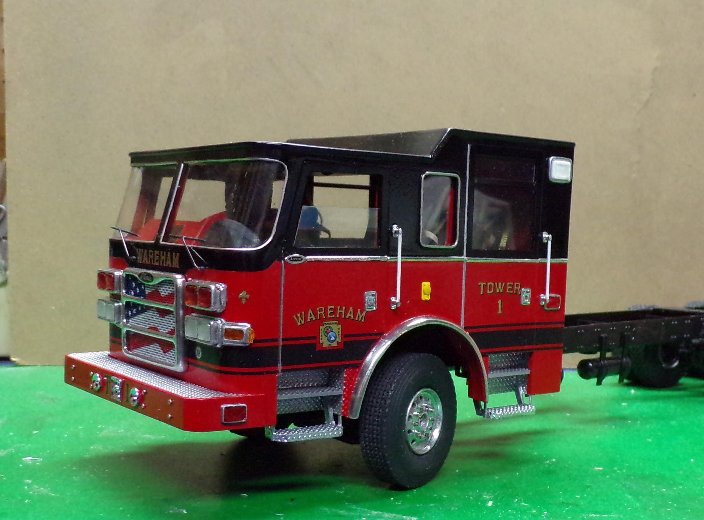
The "decals" were unbelievably hard to remove. I finally did bite the bullet and sanded them off but it cut through the white paint of the door. So I smoothed it out, primed it with Duplicolor light gray and repainted with Tamiya bright white. So far so good! -
glue for resin to styrene
Chariots of Fire replied to gary jackson's topic in Model Building Questions and Answers
Locktite for me also. Solid bond for resin to plastic. Make sure there are no solvents on the resin, though. Use the CA sparingly so it does not ooze out of the joint. You can't really clean it off a painted surface. If the plastic is unpainted you can wipe off the excess and then sand lightly to get rid of the residue. I've done this many times with good results. I've even bonded plastic to white metal with CA. Solid as a rock. -
Printing Removal
Chariots of Fire replied to Chariots of Fire's topic in Model Building Questions and Answers
I even tried a very fine sand paper and that won't cut it either without ruining the white paint underneath. I had some success, though limited, using Novus 3 but it takes a lot even with that. It may come to a repaint of the white!😬 -
Hi, Guys. I have a Motormax Diecast PD vehicle that I have been asked to repaint and re-decal. Nothing seems to take off the imprinted lettering on the doors. Tried Novus polish, alcohol and light paint thinner. Nothing seems to work. Any ideas out there as to how to get them off?
-
TIGERCAT SKIDDER 3D PRINTED
Chariots of Fire replied to Swamp Dog's topic in WIP: Model Trucks: Big Rigs and Heavy Equipment
Maybe not so much. Things like hydraulic fluid around pistons, grease drippings around articulation points, etc. bright shiny bare metal for the grabber surface and blade on the rear, dusty but not muddy tires, slightly worn tire contact surfaces. Even worn off paint where the operator walks and grab handles, door edges where constant contact wears the paint off. These kinds of things are easy to do with light washes, weathering powders and the like and they don't take away from the details of the piece. They just enhance without making it look like a muddy mess. -
TIGERCAT SKIDDER 3D PRINTED
Chariots of Fire replied to Swamp Dog's topic in WIP: Model Trucks: Big Rigs and Heavy Equipment
No mud. Just a little wear at typical places where the paint would rub off.😃 -
TIGERCAT SKIDDER 3D PRINTED
Chariots of Fire replied to Swamp Dog's topic in WIP: Model Trucks: Big Rigs and Heavy Equipment
That's really something! However, I have never seen one quite so clean and neat! Time to get it just a little bit dirty and with the paint taken off the claw and plow! 😎 -
is your rear end okay?
Chariots of Fire replied to sidcharles's topic in Tips, Tricks, and Tutorials
No. I gotta go upstairs for a couple of minutes! -
Agreed. Rustoleum paint is without a doubt the worst paint for model work. It's thick, Does not spray cleanly and remains tacky for days. It also is worthless after the first two or three uses. The nozzle cloggs and cannot be cleaned. The paint in a can might be ok for outside house paint but that is about it. Tamiya and Testors have some great colors that are rattle can ready. Not a bad way to paint in some ways.
-
Hi, Mike. Check out the IPMS (International Plastic Modelers Society) forum or Military Modelers Forum. Either place deals a lot with military aircraft builds and modeling. They might even be able to offer some advice on the ordnance the F-18 carries. I do military softskin models as well as civilian pieces and have found that more than one forum helps when I need advice. BTW. You are still welcome here, for sure!👍😉
-
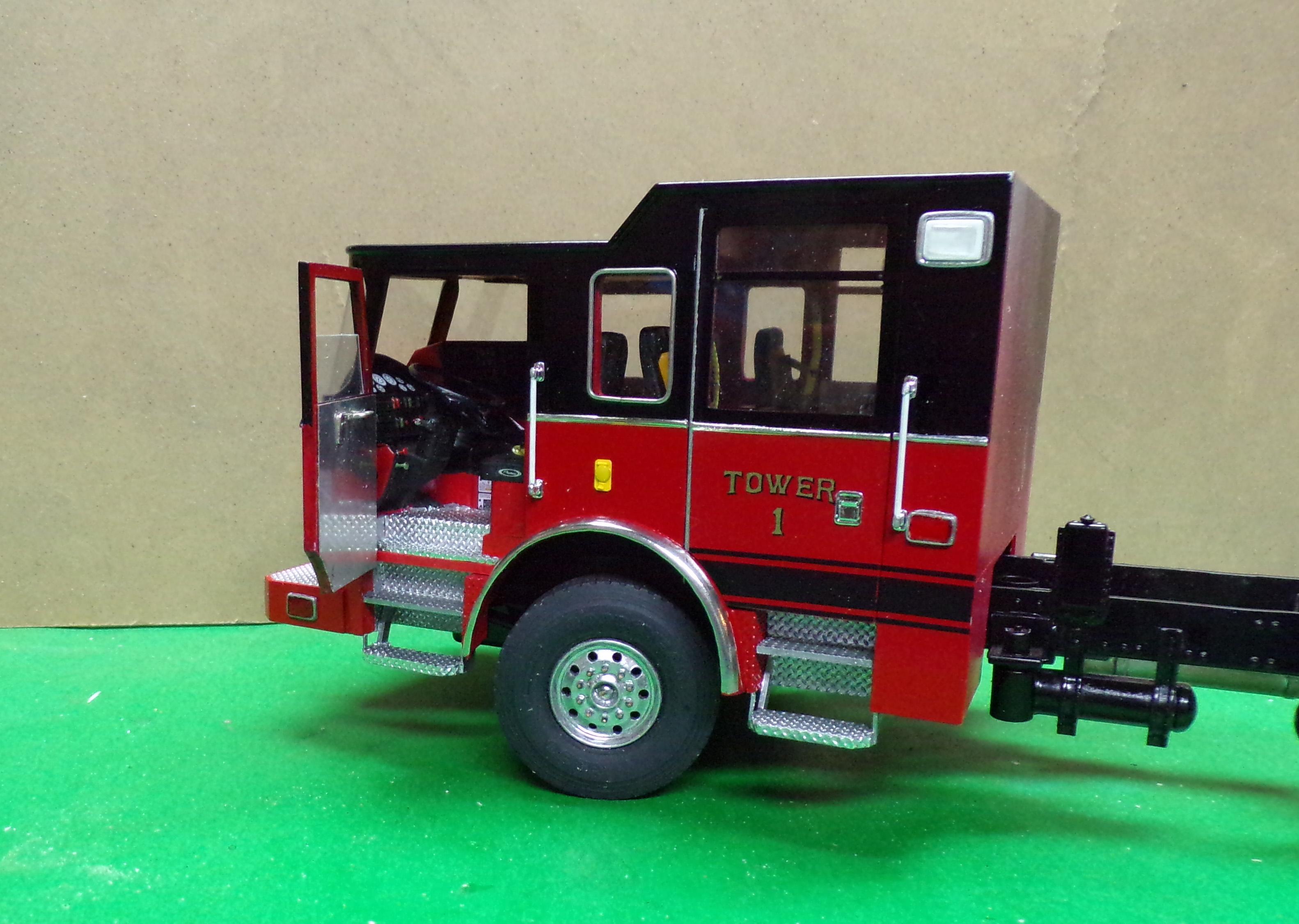
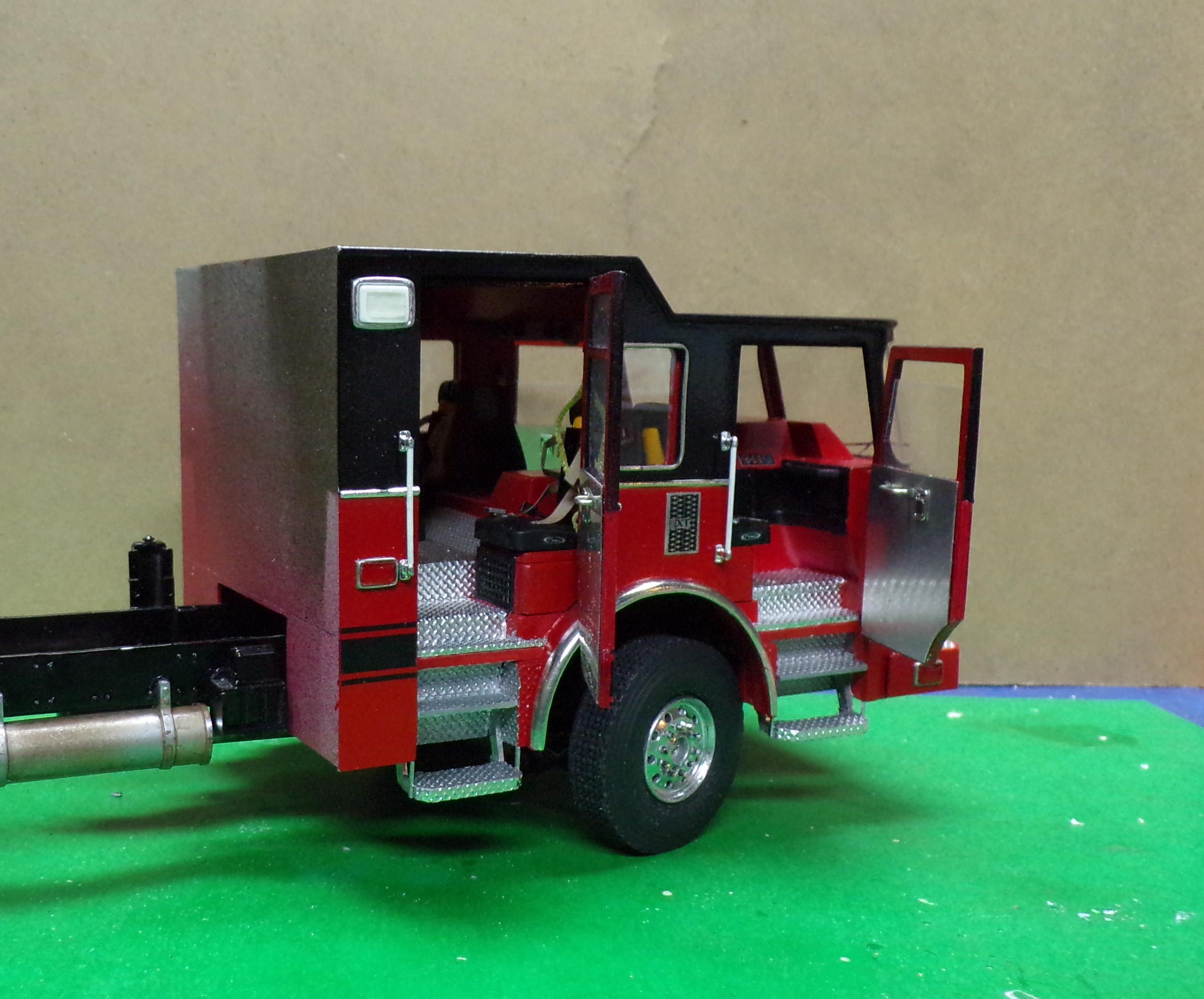
Back into it, I think! A few months back I had set this build aside for lack of enthusiasm in getting involved in the details of the body. In the process of doing other things one day, I knocked the box with the truck inside onto the floor. The officer side front door came off, the frame was snapped in two along with the underpinning of the rear tandems. It immediately went back in the box and was left that way until a few days ago. After taking another look at the damage I decided to see about fixing it. The door went back almost immediately and with only slight evidence of it having been broken clean off. It took a bit more to reassemble and reinforce the frame where it broke and even more to put the tandems back together. I had to pop off the center hubs of the rear tires to remove them but fortunately I had used CA sparingly for just that purpose. So here is where it is now and with additional study and a few photos of the real rig I just may get back into it and "get 'er done!"!!
-
Welcome, Kat. I have a friend who is from the UK and is a modeler. I'll ask him where the better hobby shops are that might have a good selection of what you are looking for. You'll find plenty of encouragement here with lots of ideas that you can try out.
-
New here, new to modeling.
Chariots of Fire replied to Elrodbeckham's topic in Welcome! Introduce Yourself
Welcome to the site, Beckham. Can I make a suggestion? Start small with just a tiny part of the diorama you plan on building. Don't think of the overall project that you have to get done all at once. It will try your patience and that is something you will have to get used to. Looking forward to seeing what you do. -
Hye. Im from Asia country. Malaysia
Chariots of Fire replied to wanyusri's topic in Welcome! Introduce Yourself
Welcome to the MCM Forum, Wan. Looking forward to seeing your work. We are here to help if you have any modeling questions. -
Got a piece of window glass from local hardware store. It sits on a wood cutting board that we discarded from the kitchen. I tape the edges with masking tape to protect fingers from getting cut. A perfectly flat surface for making frames or preparing squared up corners.
-
Carbide drills are my favorite also. I found a good source when I need to replace them. Toolbits Unlimited has all kinds at reasonable prices. I buy #74's in sets of 10 and the cost is only about $6. Also have a variety similar to Peteski.
-
Hi, Greg. Has 5 holes just like the mounted ones. The outside ring with 12 bolts is separate.
-
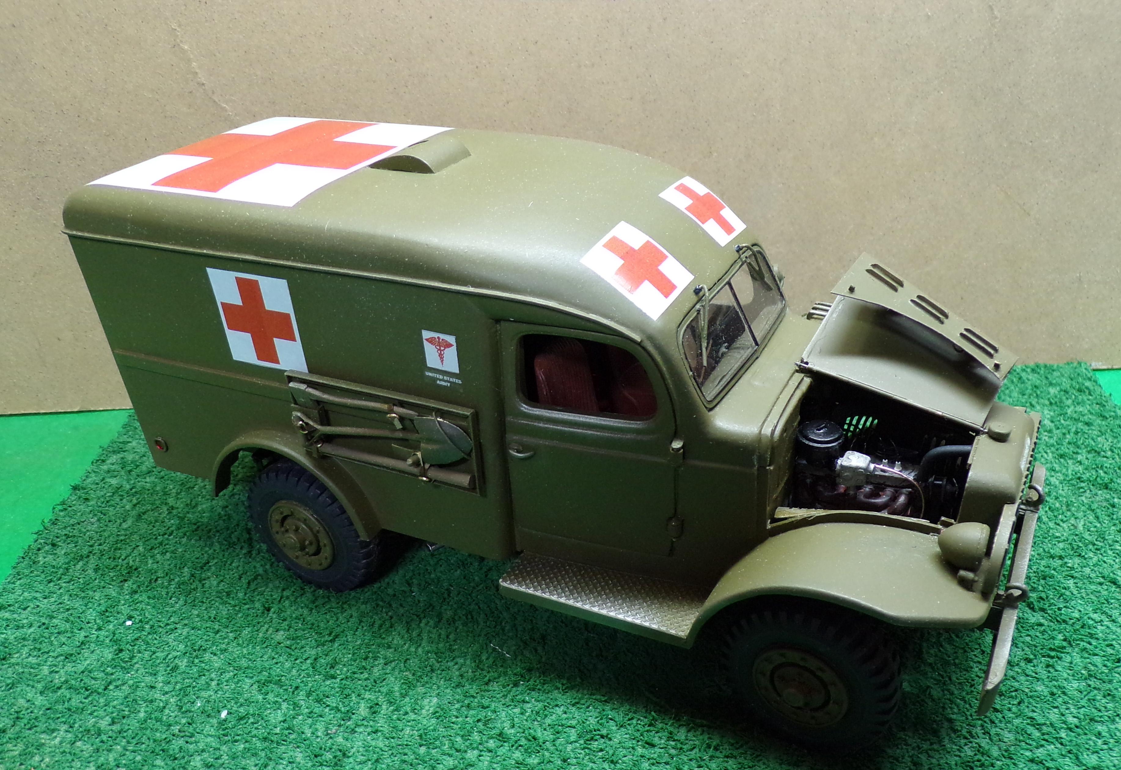
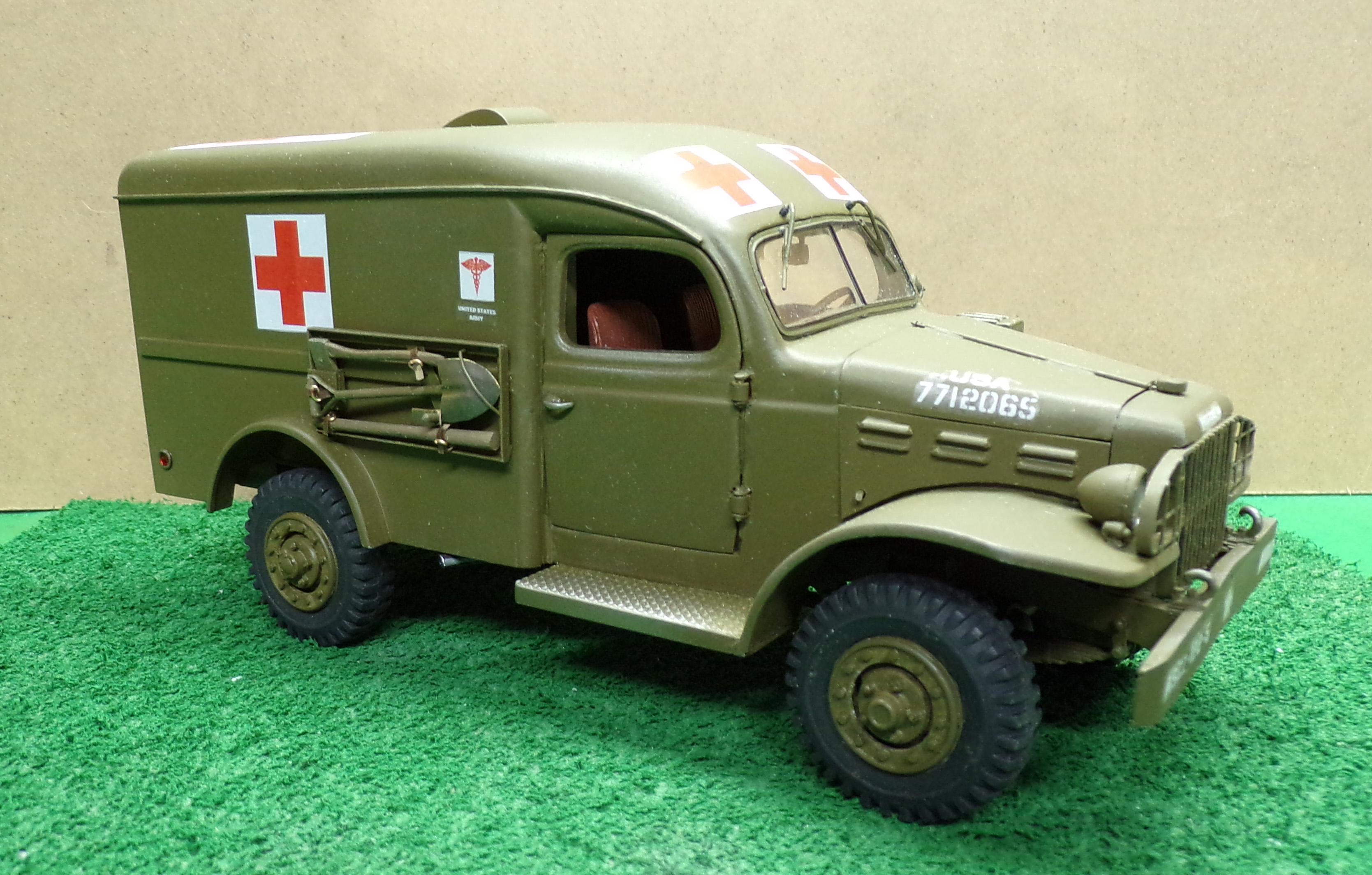
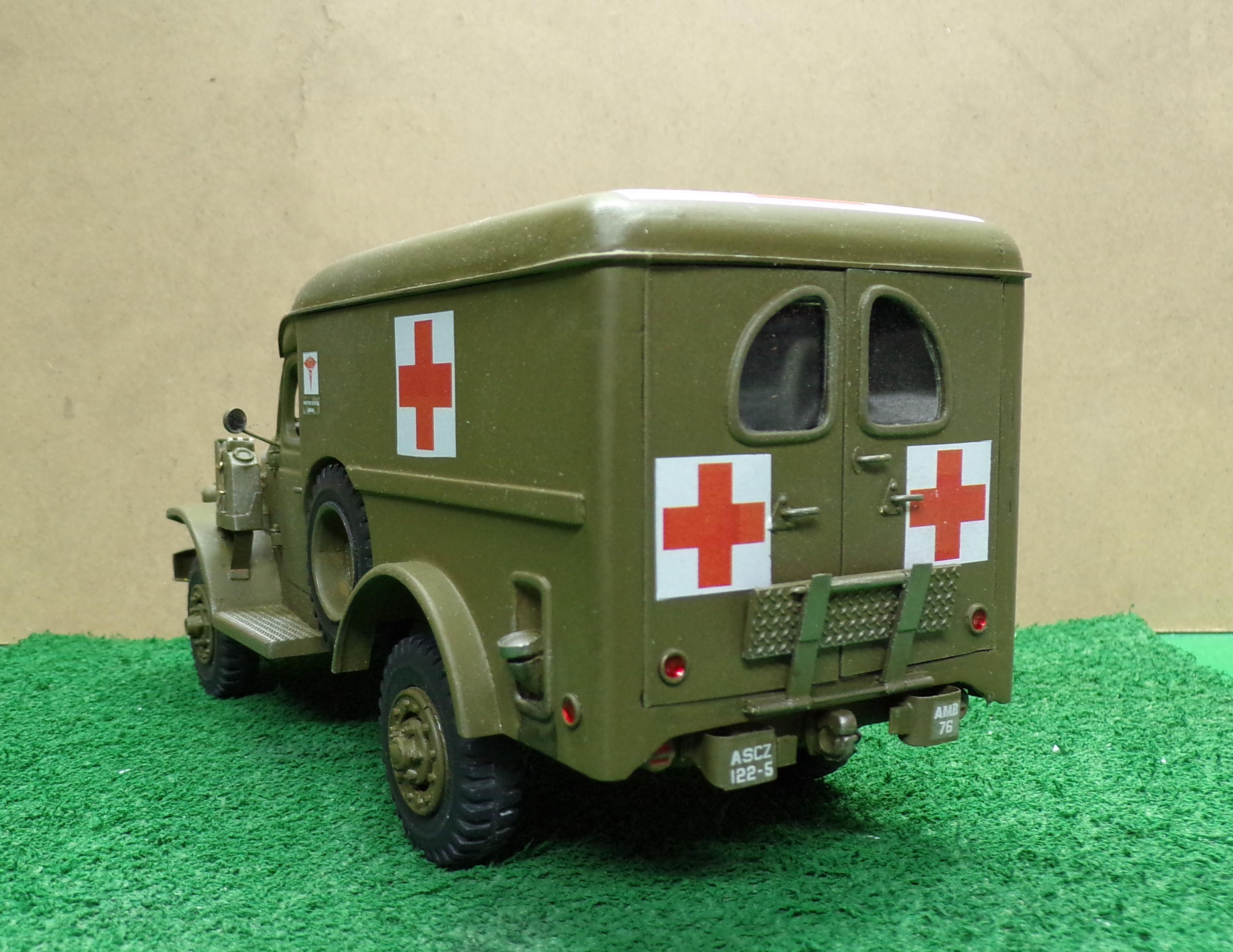
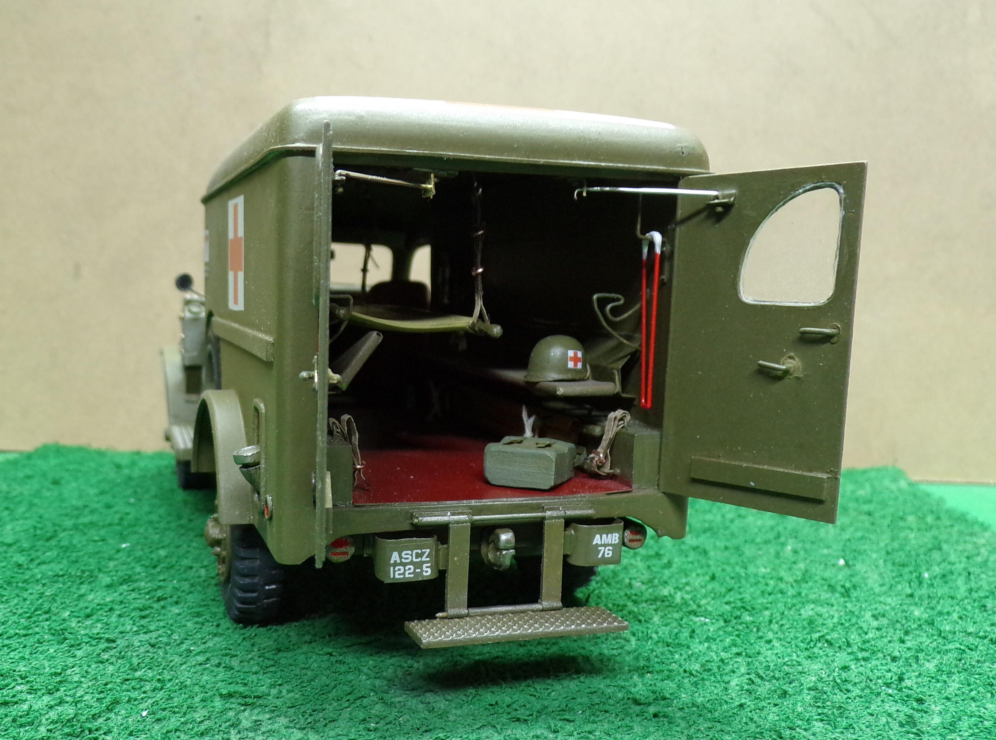
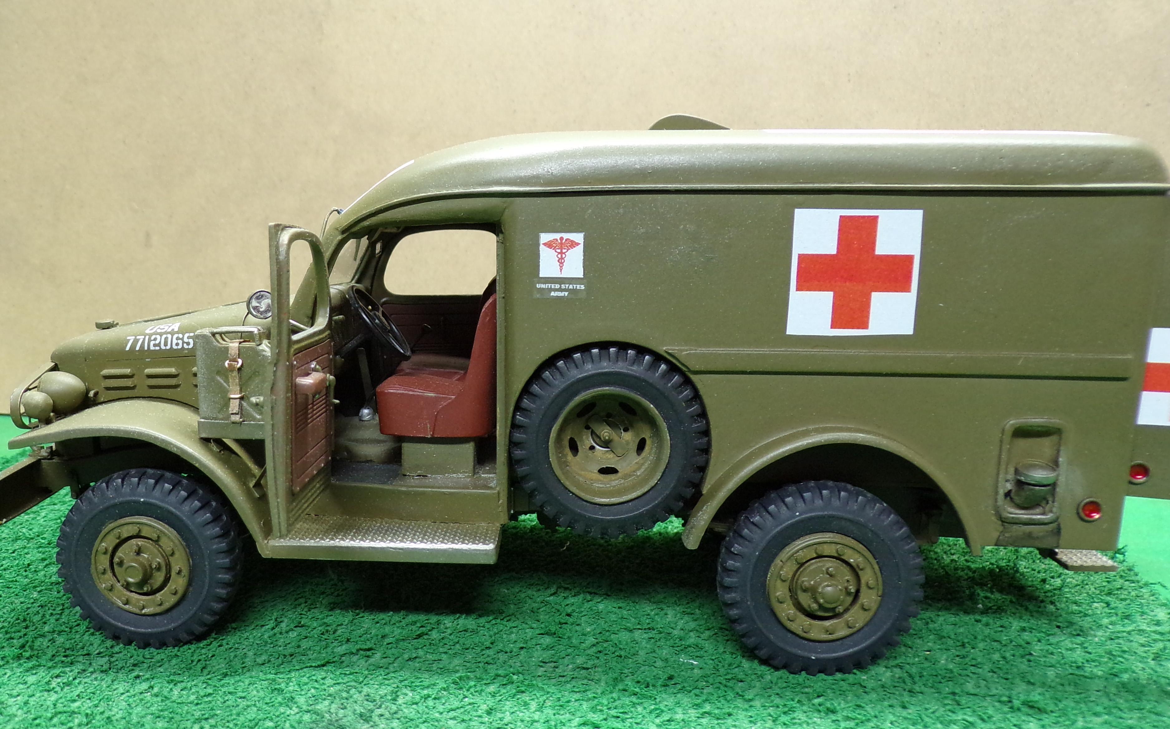
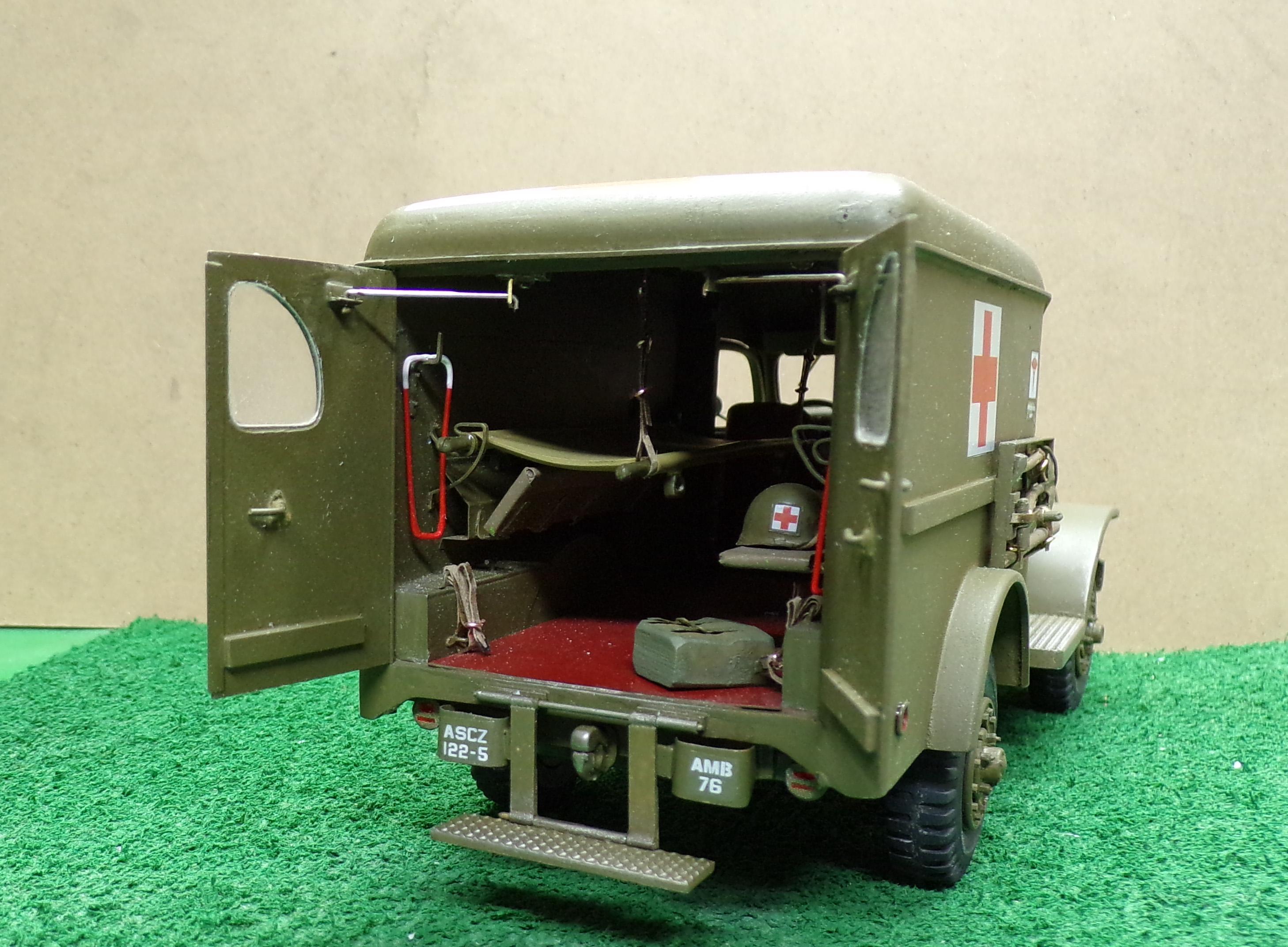
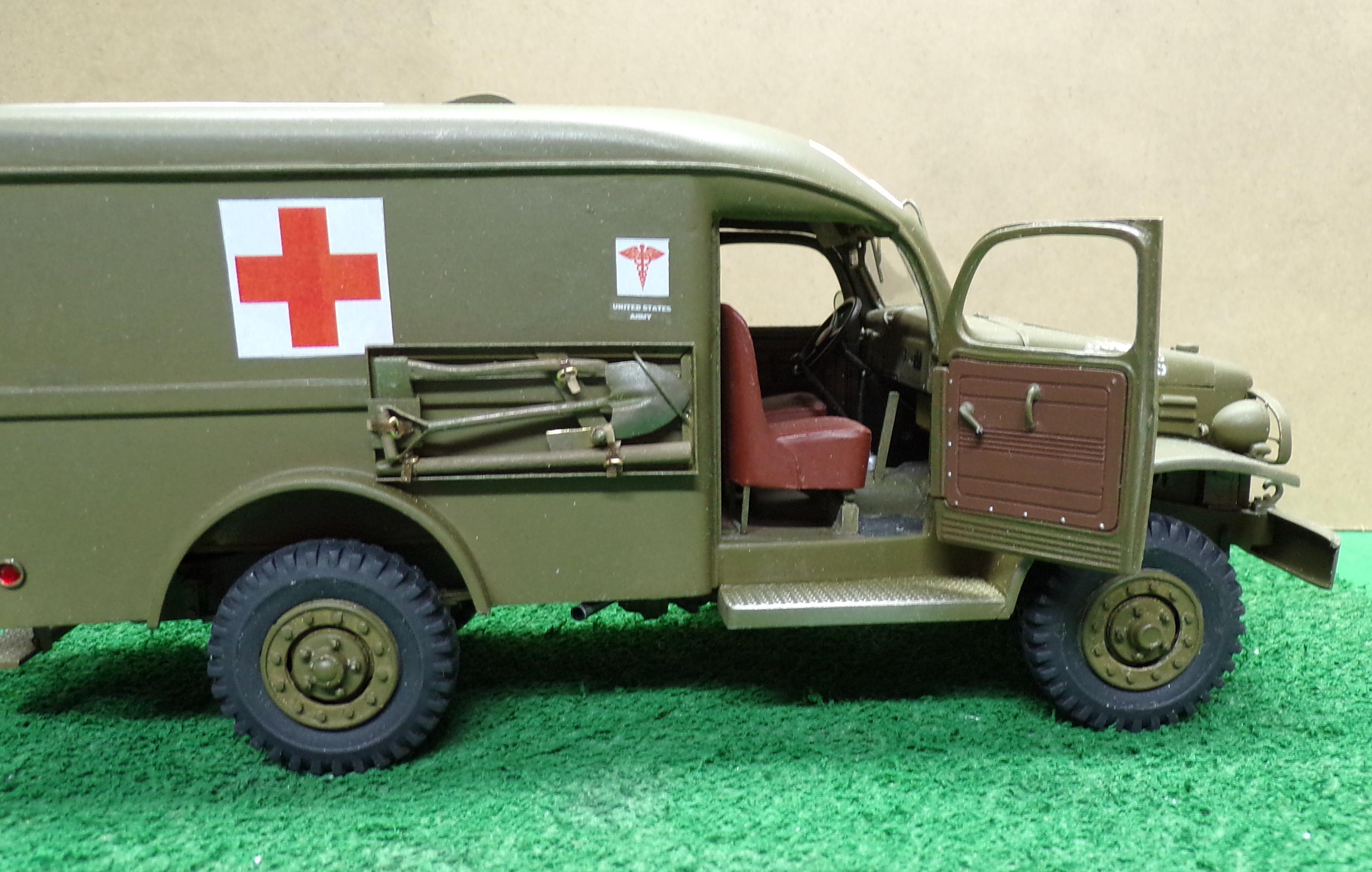
After a bunch of fiddly stuff finally was figured out and completed, the ambulance went to the paint shop and to the sign shop for the decals. Finished it up with a completed interior, GI gas can and pioneer kit for the passenger side. Not sure what will be next. A few days off from an intense work week and a clean work bench may lead to something. We'll see.
- 13 replies
-
- 11
-
-