Chariots of Fire
-
Posts
2,777 -
Joined
-
Last visited
Content Type
Profiles
Forums
Events
Gallery
Everything posted by Chariots of Fire
-
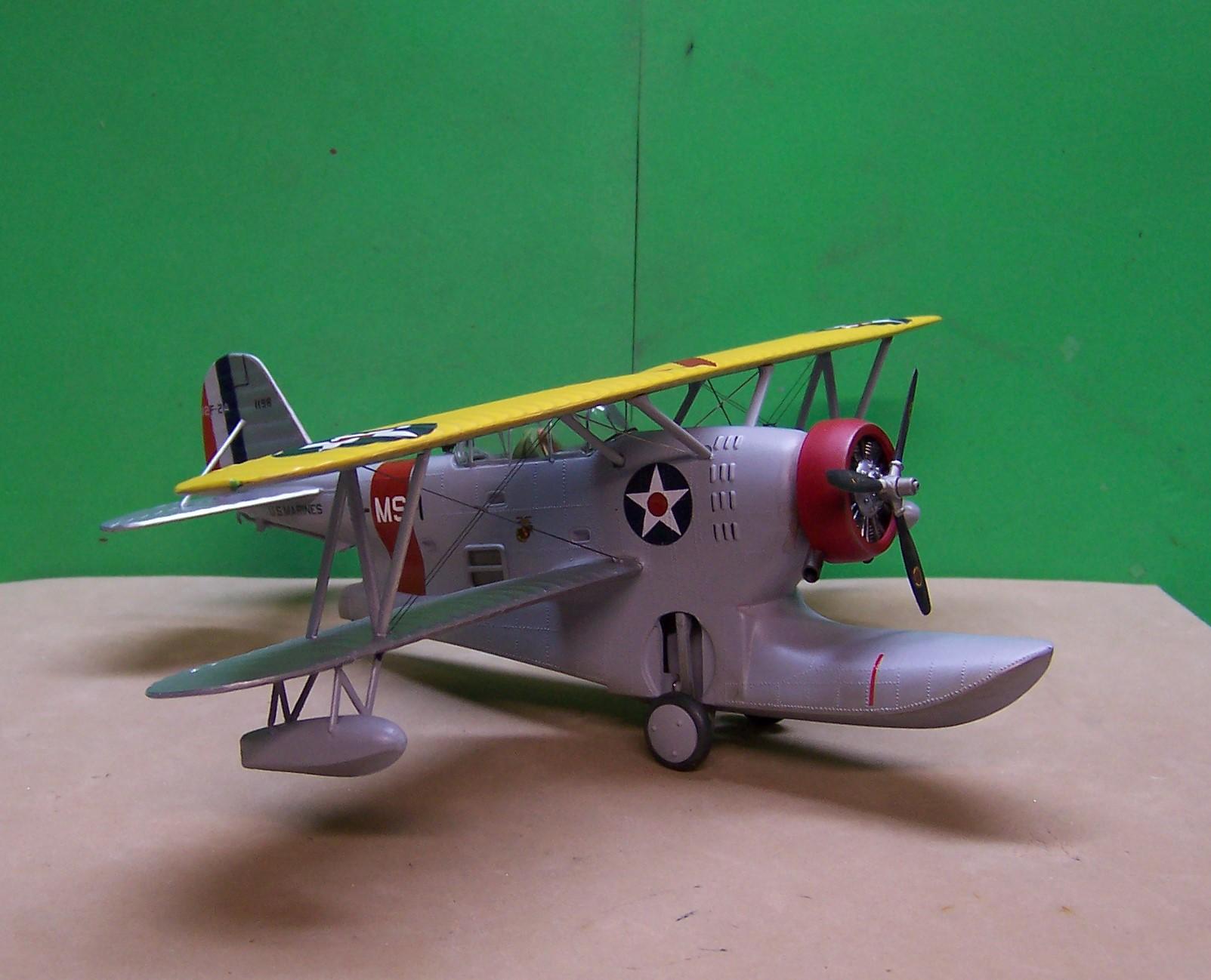
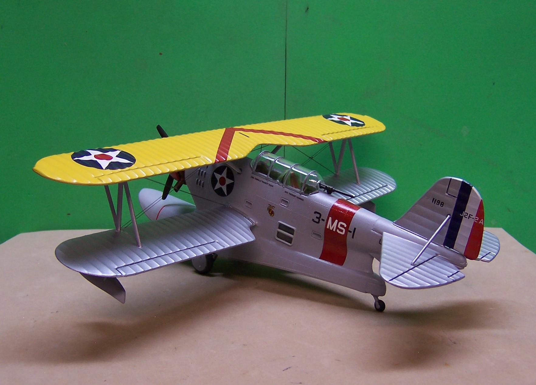
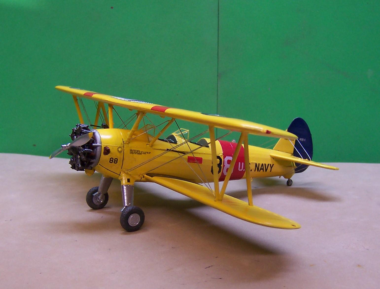
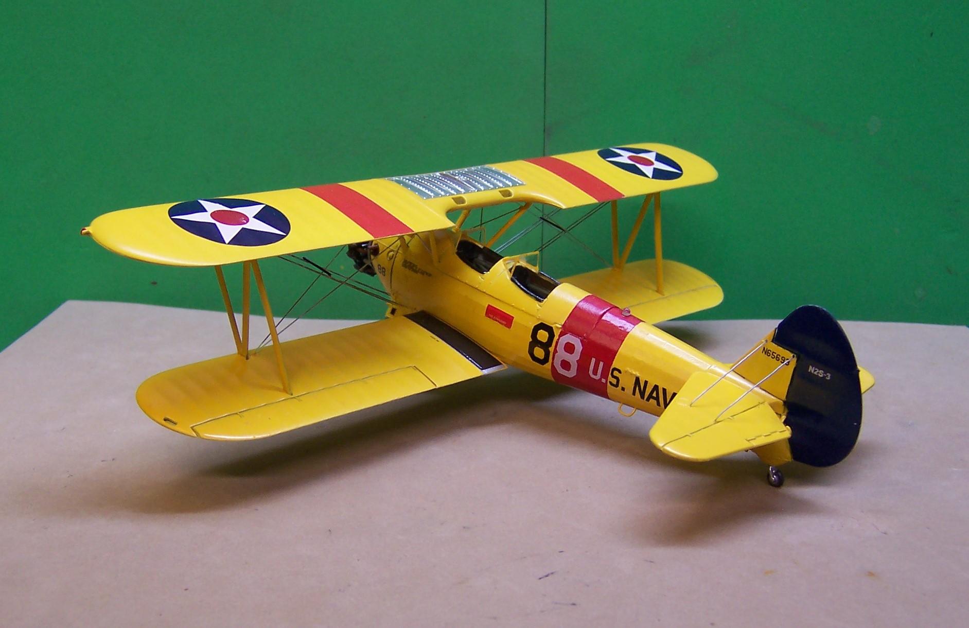
 Both are great builds! I am also a fan of that era. Have a few of my own.
-
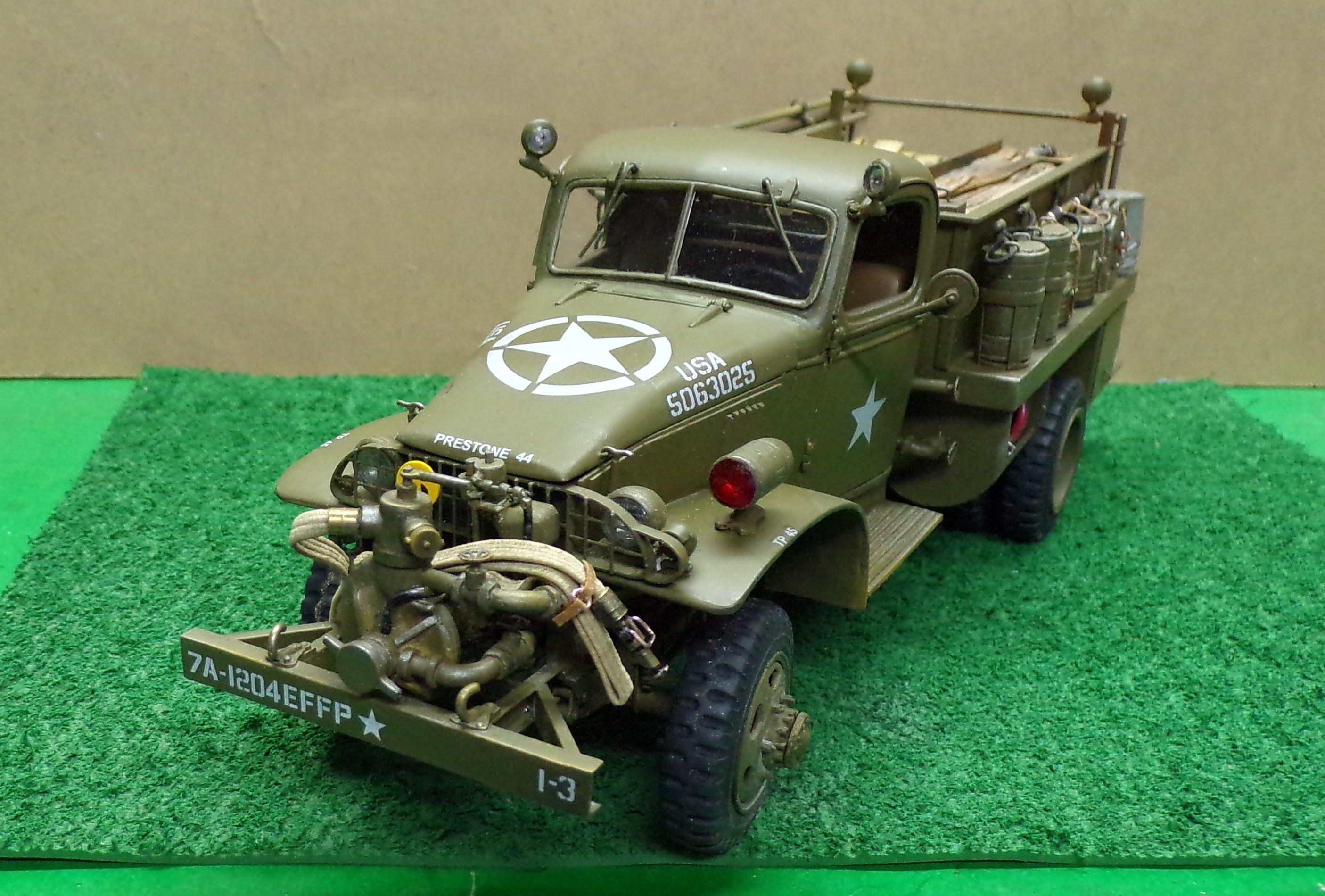
Pretty basic materials to make the straps. A strip of brown paper bag and some craft wire. I modified a small set of pliers so that I could bend the wire into a consistent small loop. I either cut both ends off or leave one that can be used to insert into a pre-drilled hole to secure it.
-
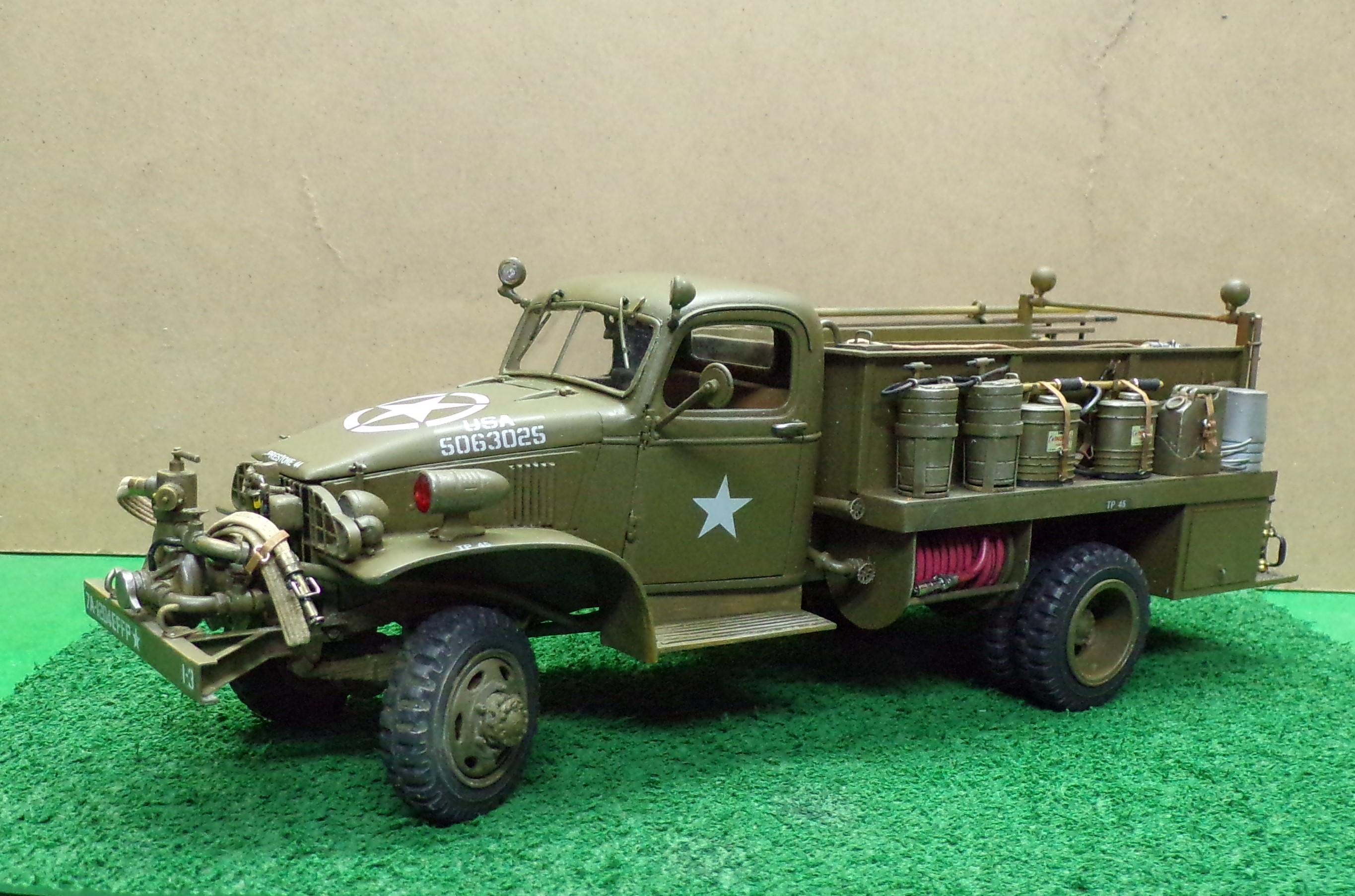
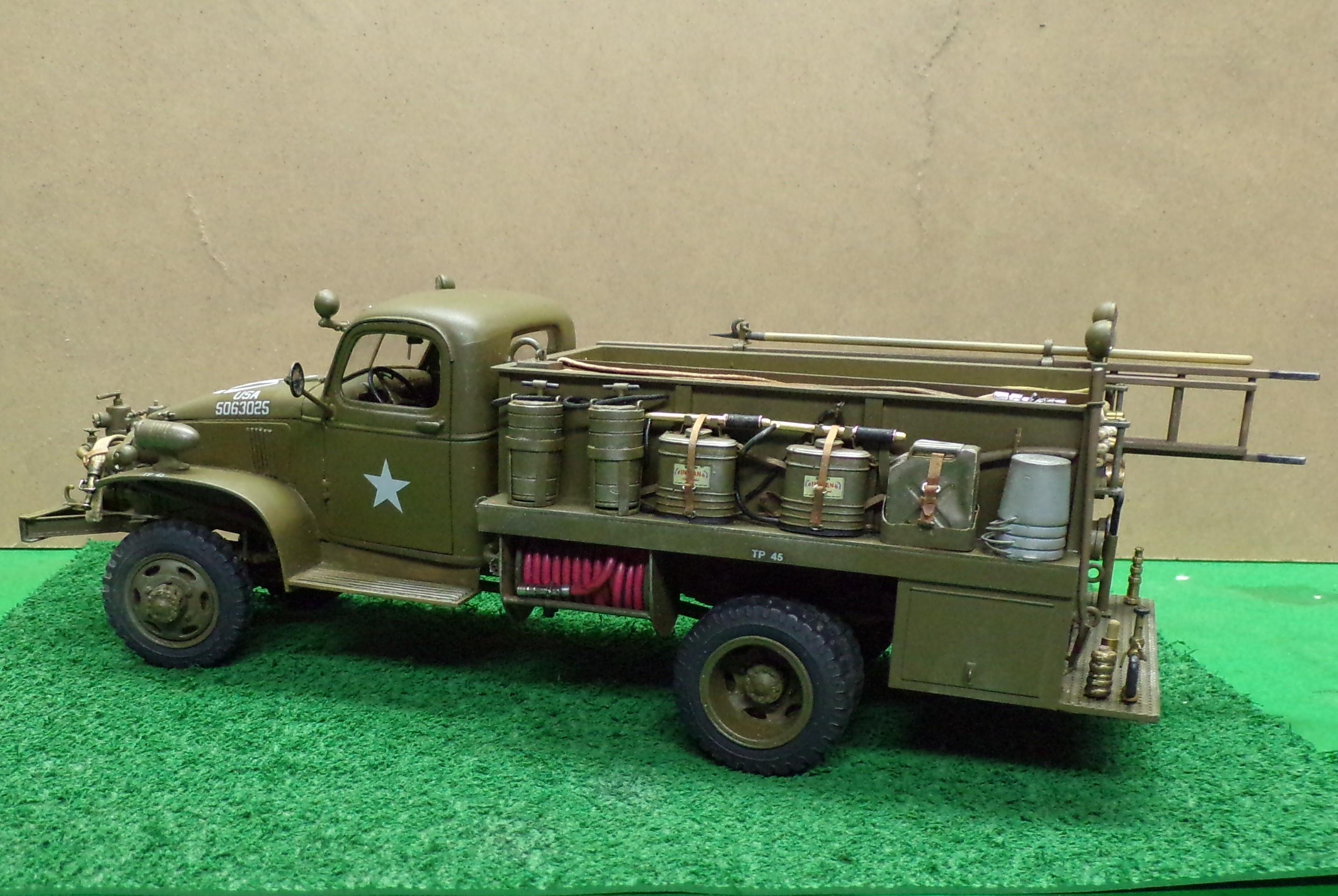
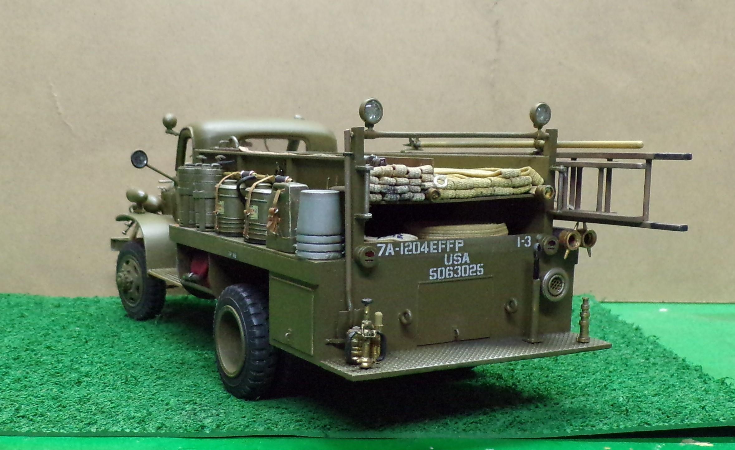
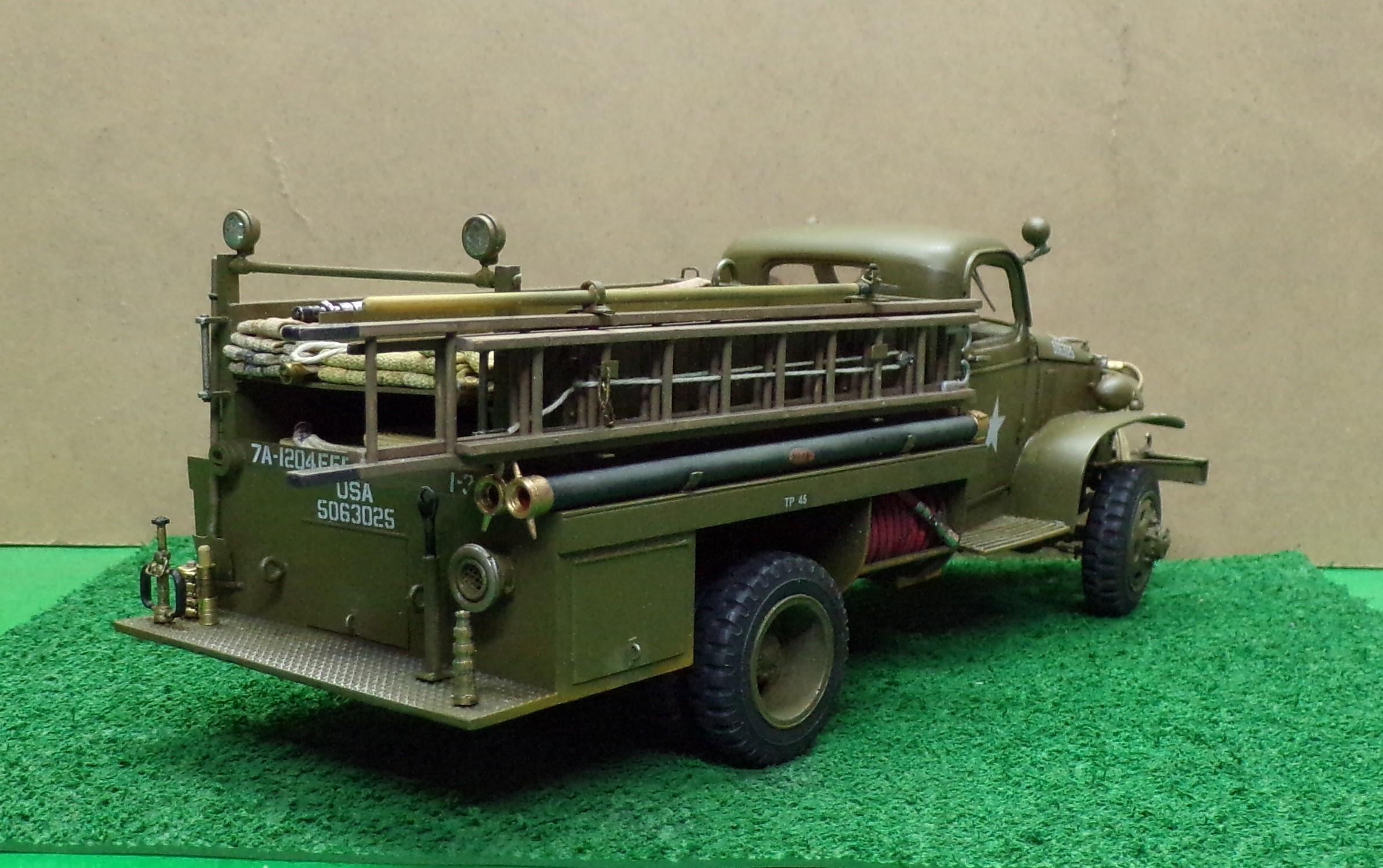
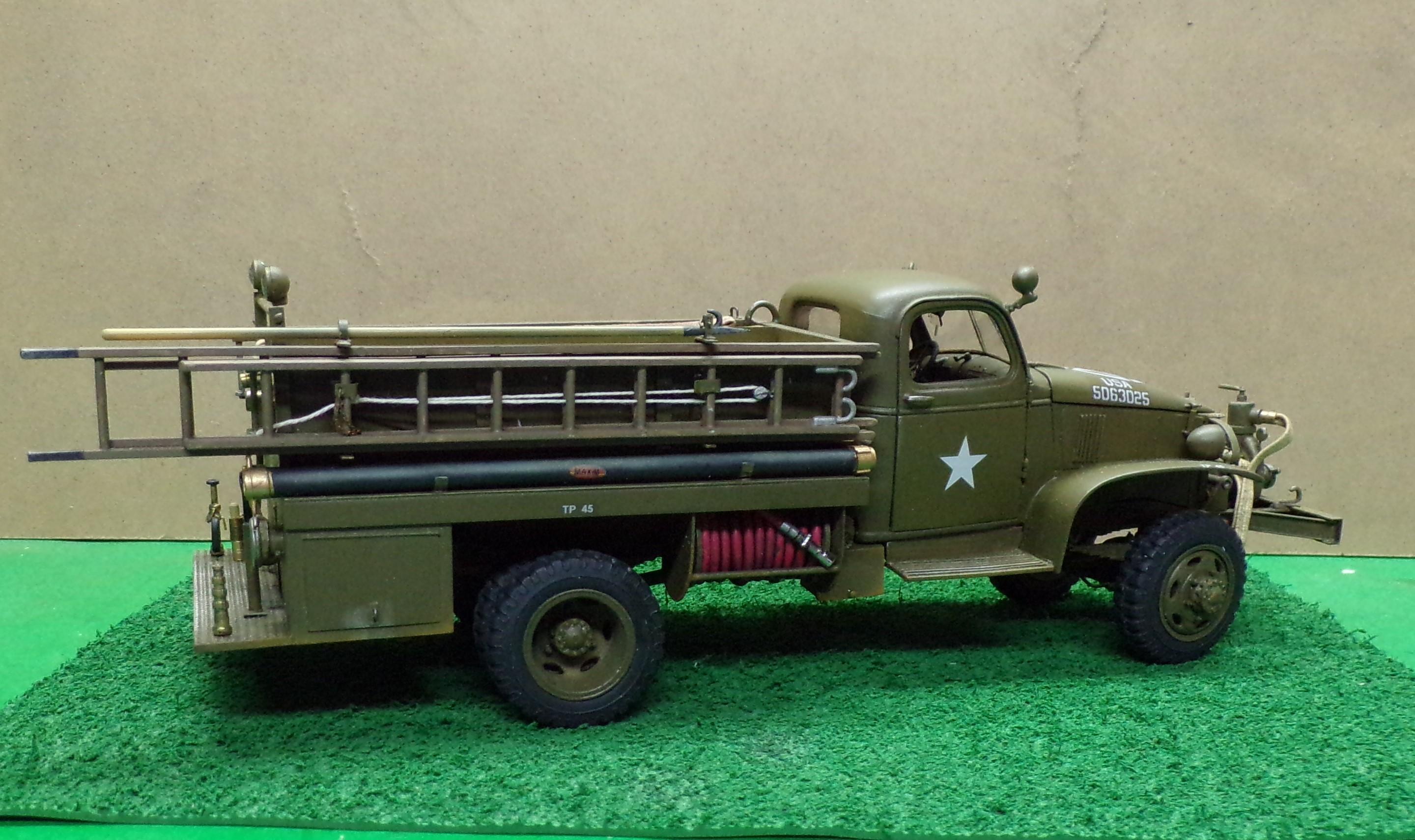
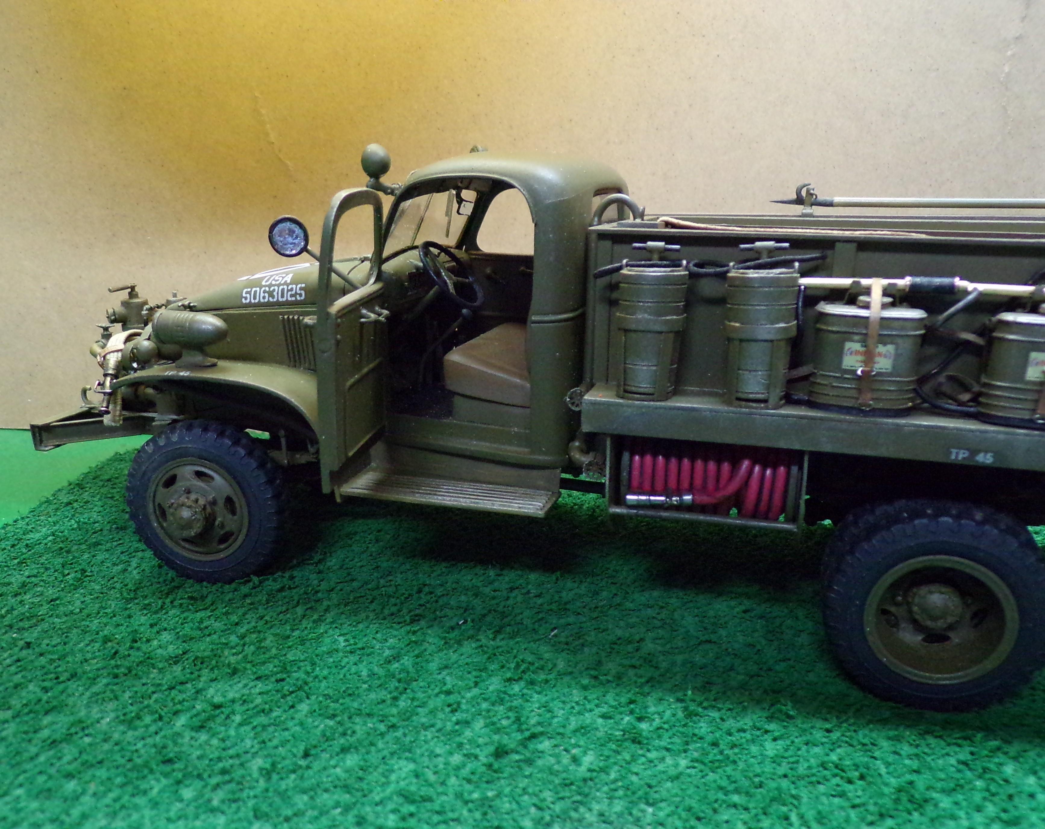
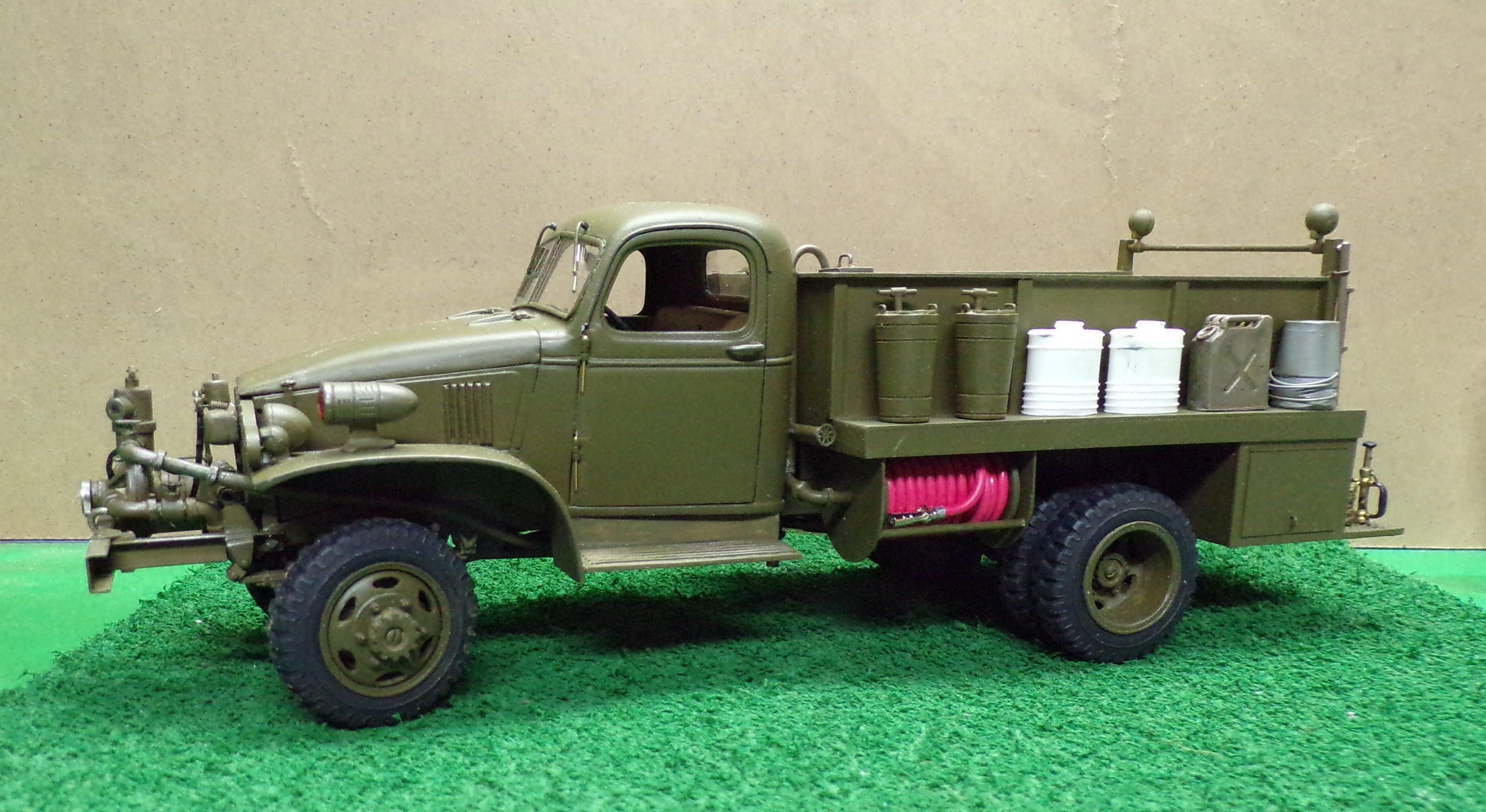
With the exception of a couple of minor adjustments, the build of the Class 325 pumper is finished. The last of the details have been installed but the rear view mirror is not very good. It needs to be slightly smaller and a lot smoother. I tried something this time that I have not done before and the results are not up to snuff. The engine photo is out of focus too. That needs to be shot over. In the meantime here is where the build is.
-
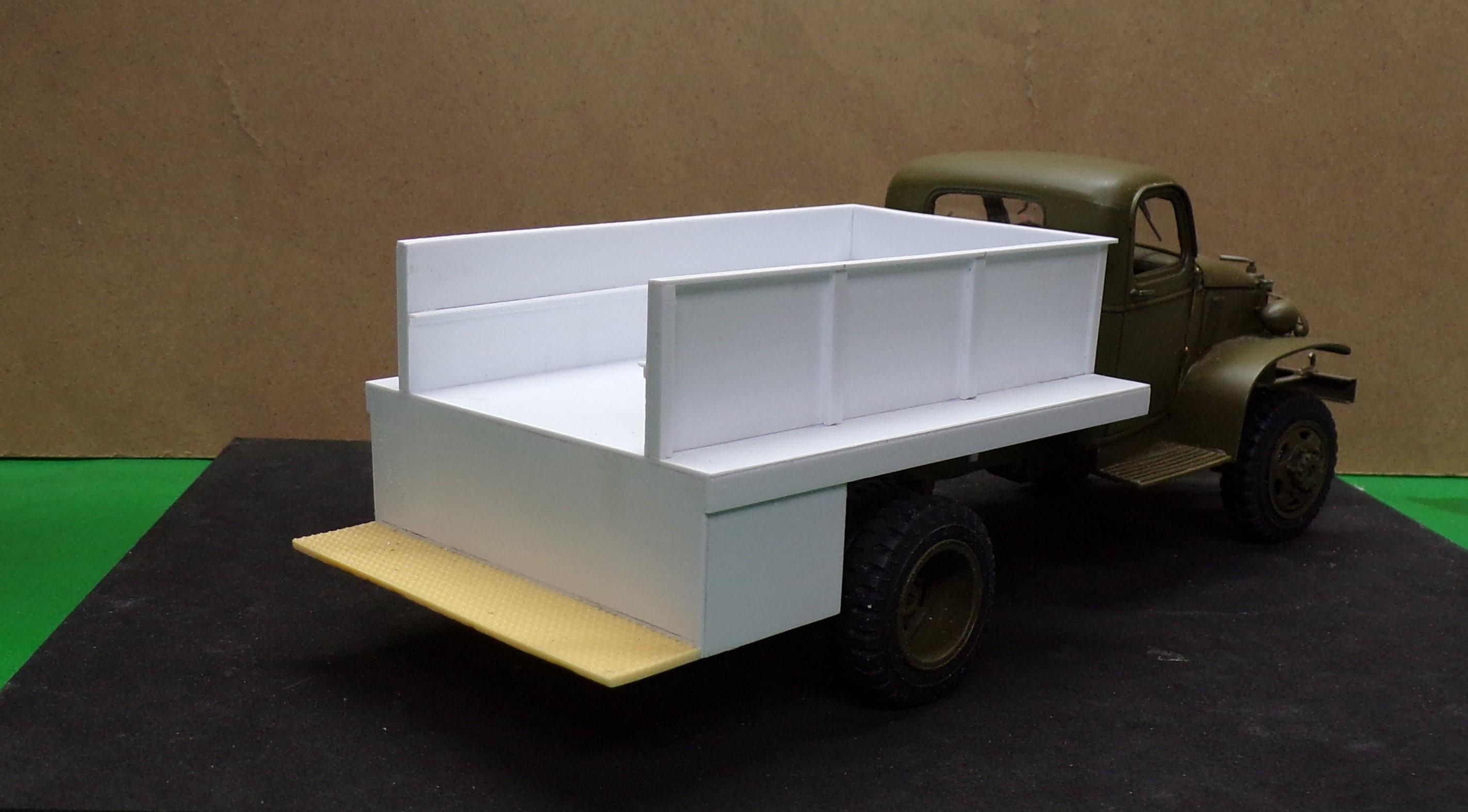
A little of both, Mike, depending on the need. Not too much different in the pace of the work. The time consuming part was the frame work and detailing of it. Cab or course was right out of the kit box except for opening the doors. I had a little trouble finding the right material for the hose bed but I now have a section of it ready for loading once the stain dries. Thanks for the comments. Much appreciated.
-
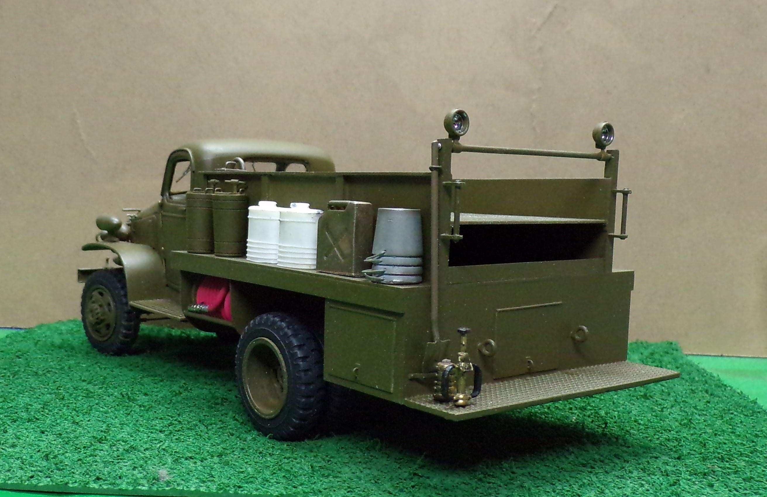
HI, Brian. I turned a piece of aluminum rod into the shape you see in the photo, made a mold and cast a piece in 2 part resin. Pieces of craft wire make up the handles. A little paint and highlighting make it look like the pails are stacked when really it is only one piece.
-
Getting into details now that the body has been painted and installed. Quite a few of the detail items are done but others need finishing up. Ladders and pike pole need to be built up and two lengths of hard suction need to be added to the right side of the body.
-
Western Star 4900 FA plow truck
Chariots of Fire replied to BK9300's topic in WIP: Model Trucks: Big Rigs and Heavy Equipment
Can I recommend a different method of sealing those light lenses? Instead of CA which may fog or not give you any time to set them in place where you want them, use 2-part clear epoxy but first, coat the inside of the bezel with chrome silver and let it dry. The epoxy will give some working time and a very little bit goes a long way in securing the lenses. I use Bob Smith epoxy. Does not turn yellow with age. -
Western Star 4900 FA plow truck
Chariots of Fire replied to BK9300's topic in WIP: Model Trucks: Big Rigs and Heavy Equipment
HAH! That curve can be a sharp one to get around!!😆 Thanks for the info. -
Western Star 4900 FA plow truck
Chariots of Fire replied to BK9300's topic in WIP: Model Trucks: Big Rigs and Heavy Equipment
Hey, Brian. What has been your learning curve for using Sketchup? I'm familiar with 2-dimensional CAD, having used it in my engineering business but the third dimension and how to position things is an altogether different thing. Not ready to start printing in 3D but would like to learn the design aspect of it first. -
Western Star 4900 FA plow truck
Chariots of Fire replied to BK9300's topic in WIP: Model Trucks: Big Rigs and Heavy Equipment
Funny thing about keys. I have 2 keys to my GMC Canyon. Tried the spare today and it would not start the truck. Turns out the key itself has to be programmed! No simple info in the owner's manual. Had to go to the GMC dealer to find that out. Started truck with older key, turned it off, inserted the spare and it got programmed immediately and the truck started. Talk about overkill!! -
Western Star 4900 FA plow truck
Chariots of Fire replied to BK9300's topic in WIP: Model Trucks: Big Rigs and Heavy Equipment
That's got to be one of the most detailed models I have ever seen. And superbly done to boot! Don't forget the key for the ignition!🤣 -
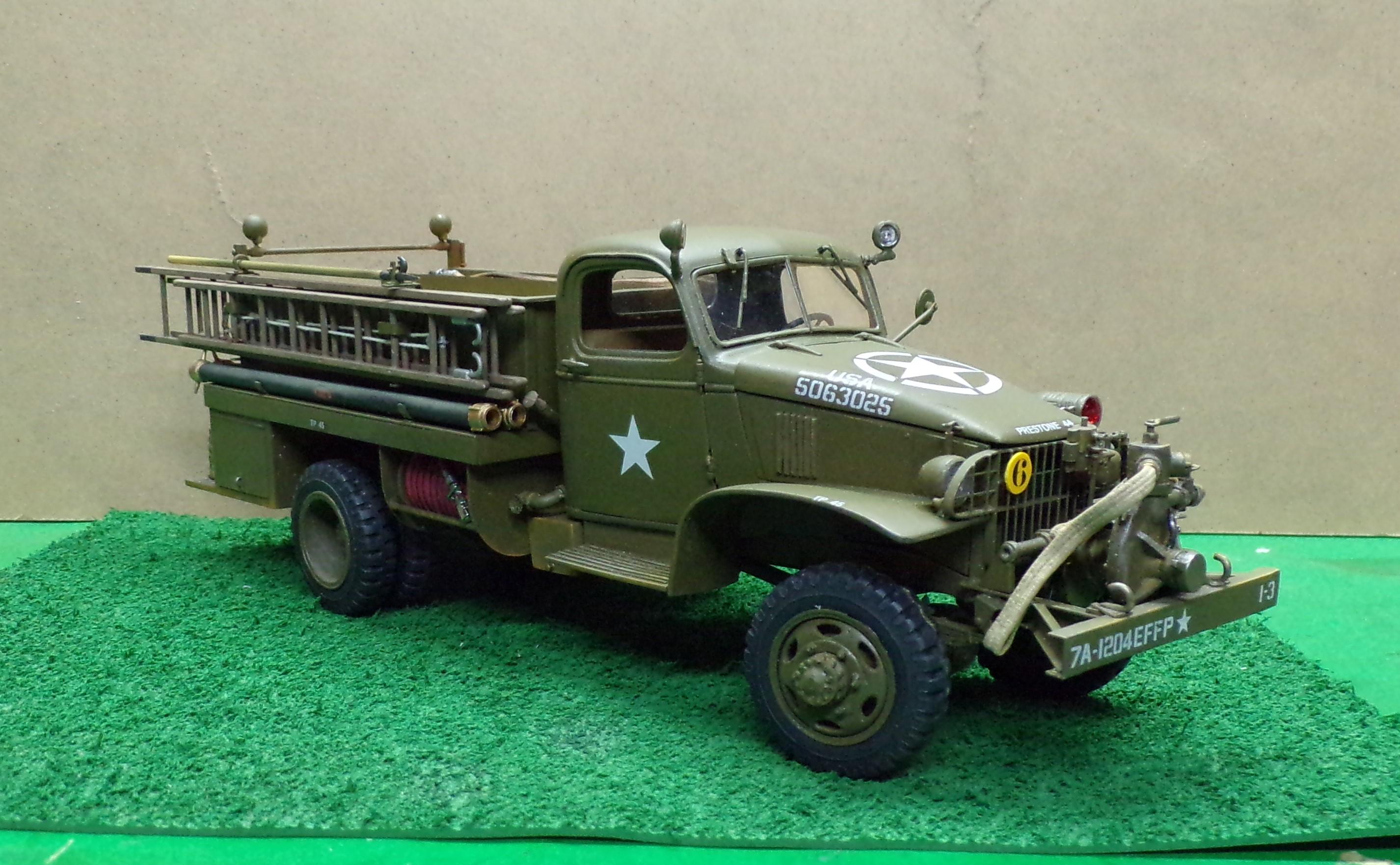
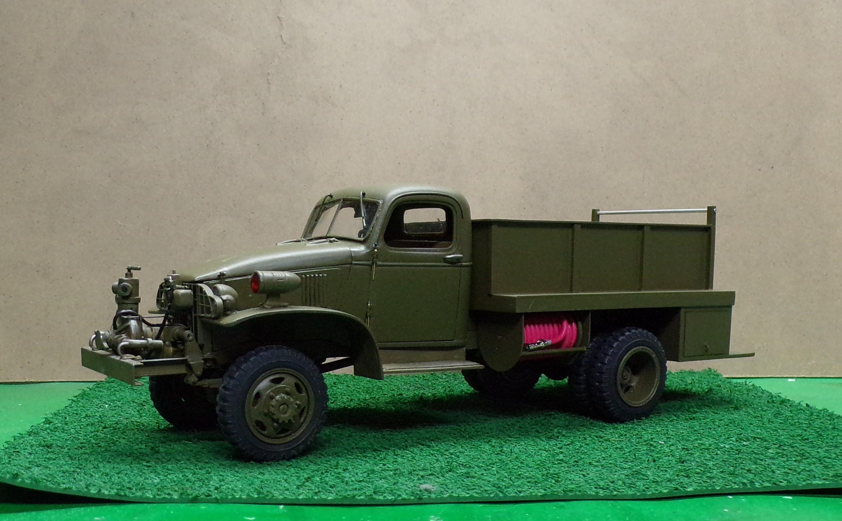
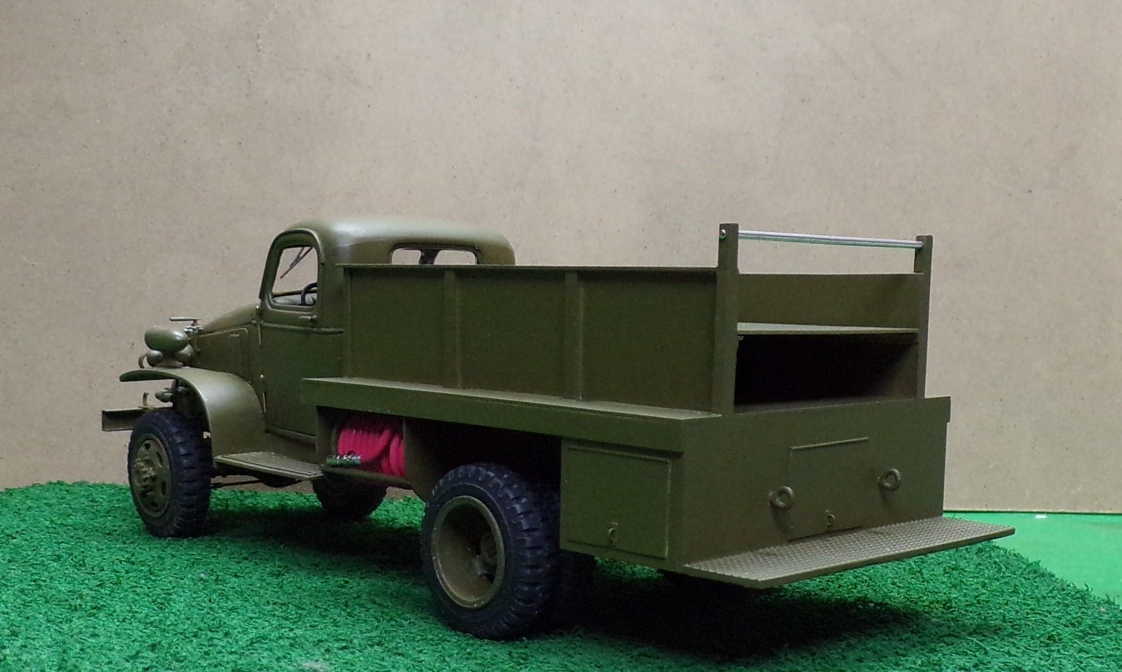
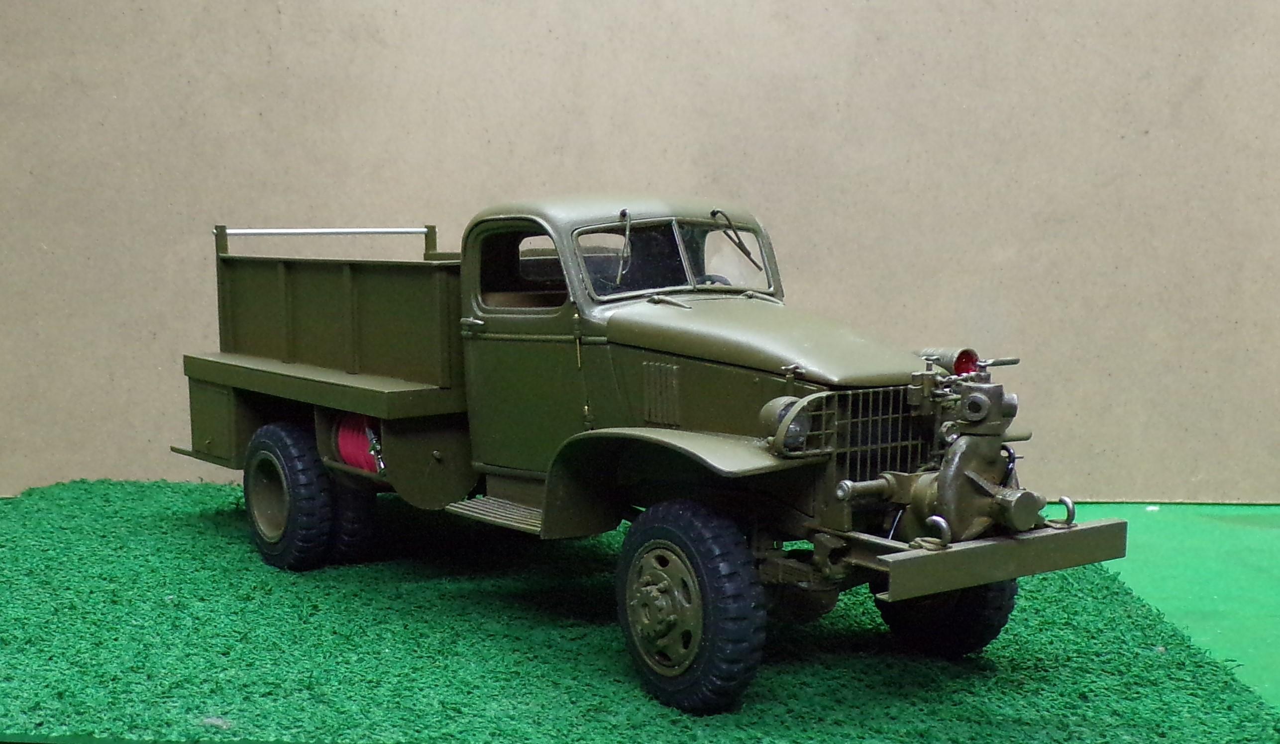
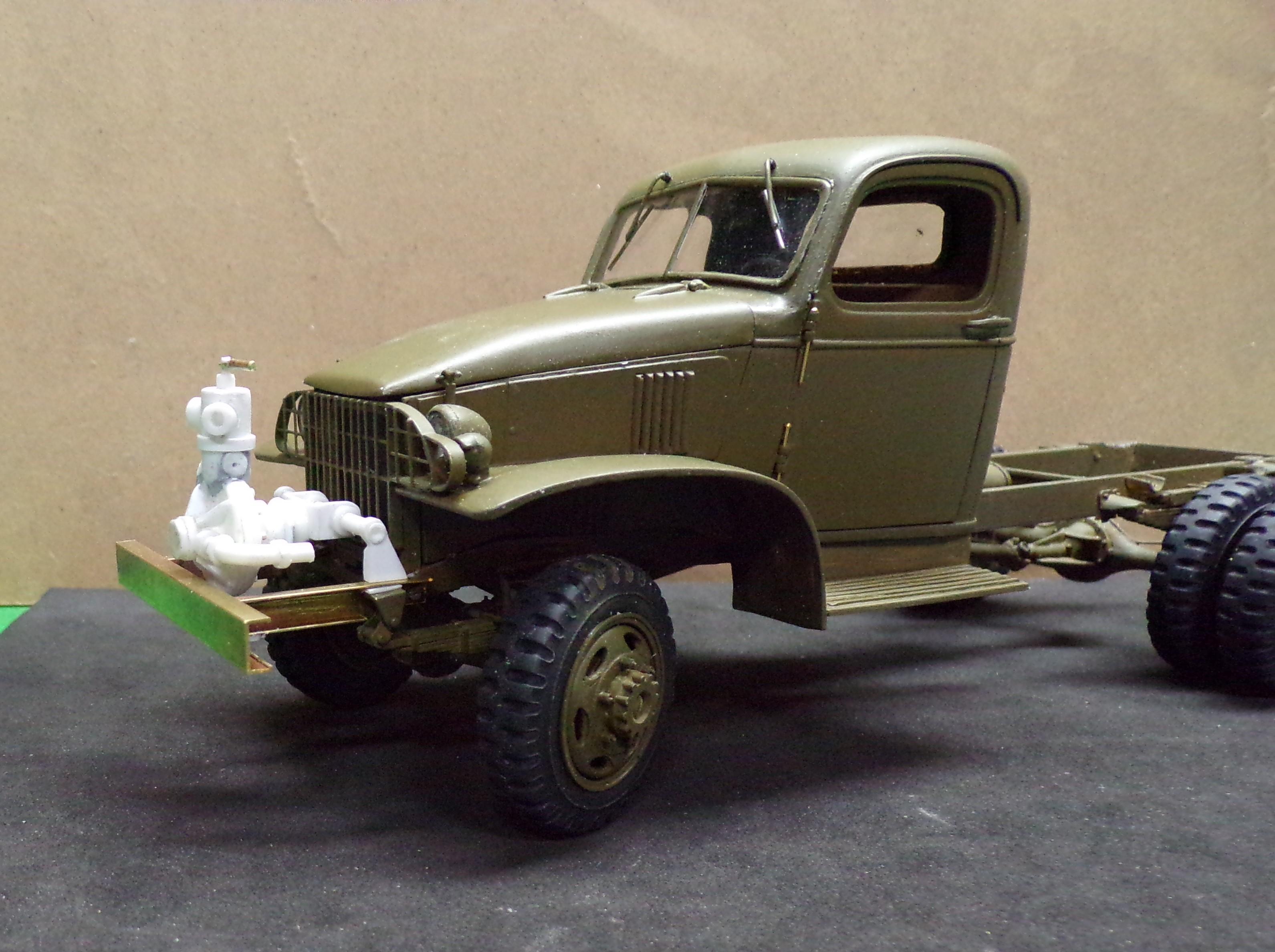
Update on the build. Got some painting done and work was started on the Barton front mounted pump and the body. Body stock is 0.030" Evergreen sheet and strip. Hose reels need to be built for under the front of the body on both sides. Plumbing for the pump still needed as well.
-
AITM is back
Chariots of Fire replied to PierreR89's topic in Truck Aftermarket / Resin / 3D Printed
If the resin of the Ford F-8 is as good as Dave's was, you should be able to scribe through the lines of the hood to separate it. I did that on the Reo Gold Comet that Dave cast so I could do a model with an opening hood. Worked fine. -
Welcome to the forum! Plenty of neat stuff to see and lots of great info to take in.
-
Those last photos should be of some help. When you compare the height of the cab to the wrecker frame there is some consistency. If you can find one or two dimensions that are relatively proportional you might be off to a start. Other pieces that you can see in the closeups can be made to fit pretty close.
-
How about scratch building one?? Get some photos, Holmes info or measurements and go at it! 😎
-
M543 Wrecker
Chariots of Fire replied to Warren D's topic in WIP: Model Trucks: Big Rigs and Heavy Equipment
Nice work, Warren. I was going to suggest washing all of the 3D parts in detergent and warm water first but you beat me to the punch! Going to be a BIG truck even for 1/35 scale. The basic M52 is a 5 tonner, I believe, and this one looks similar. -
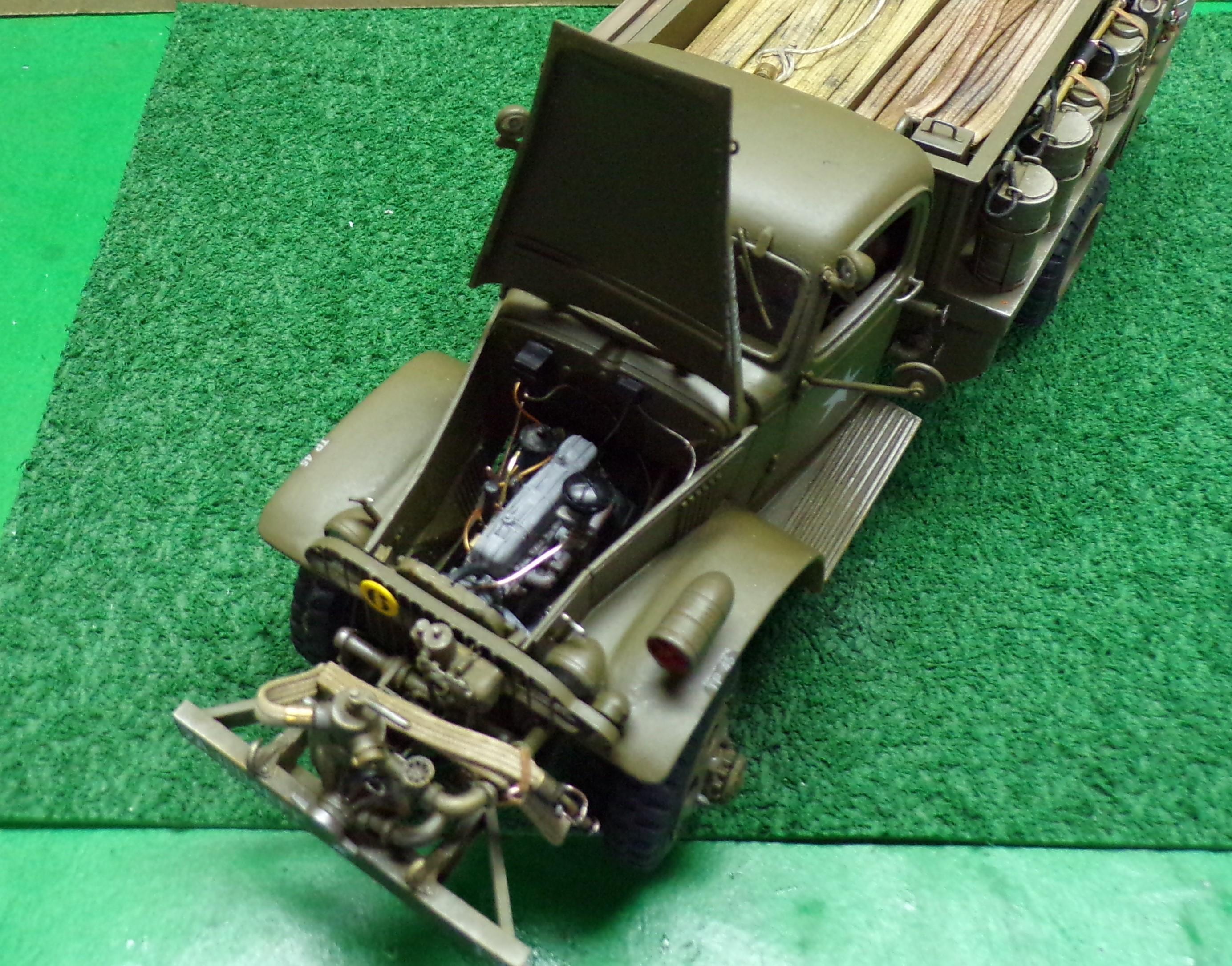
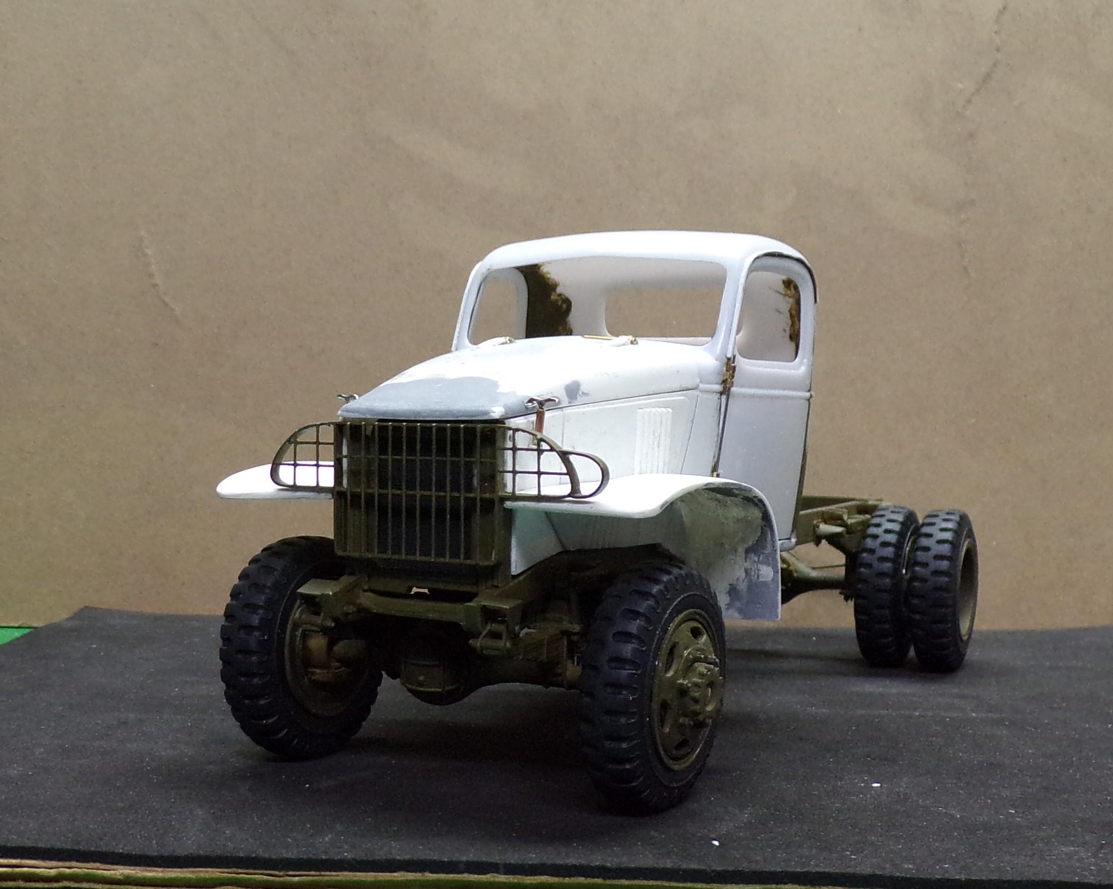
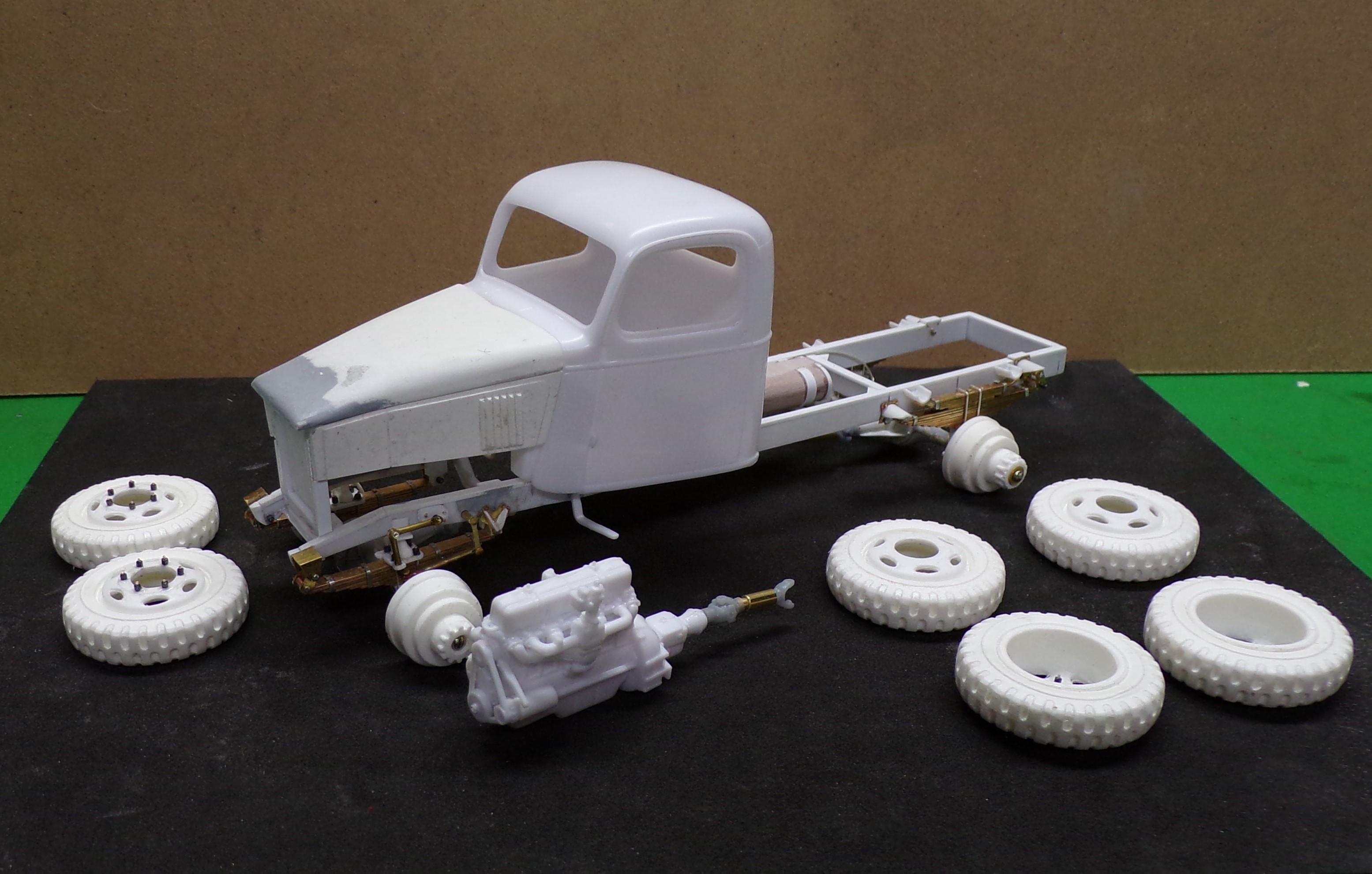
Ok. Fenders have been attached along with panels for underneath. The engine is in and secure. The hood latches have been completed along with the hinges. I brush painted portions of the cab interior that would be hard to hit with a rattle can. Overspray on the outside will cover any unevenness of the brush work inside. Makes it so much easier to do when it comes to paint. The frame has been given a coat of OD. Still some washes needed to highlight the various details. Tires and wheels are ready for mounting. I made the hood hinges out of pieces of door hinge stock, a piece of small brass channel and some plastic. The hood latches are made of brass tubing and common pins. They are glued in position and have a small U-shaped piece of wire on the sides of the hood as latch catches.
-
Transporting Completed Models
Chariots of Fire replied to Ralphie's topic in Tips, Tricks, and Tutorials
I use plastic storage containers. Models are placed on a padding of paper towels or something similar. Then more paper towels are placed in between models and around the edges of the container to keep them from rubbing up against each other or against the container. Thin, soft foam stock works as well. No need for extra protection against cold or hot if you are not going to be in such environments for long periods of time. -
Hey! It's gonna have a RED light! 😆
-
They are after market, Brian. Way too small to make by hand!😎
-
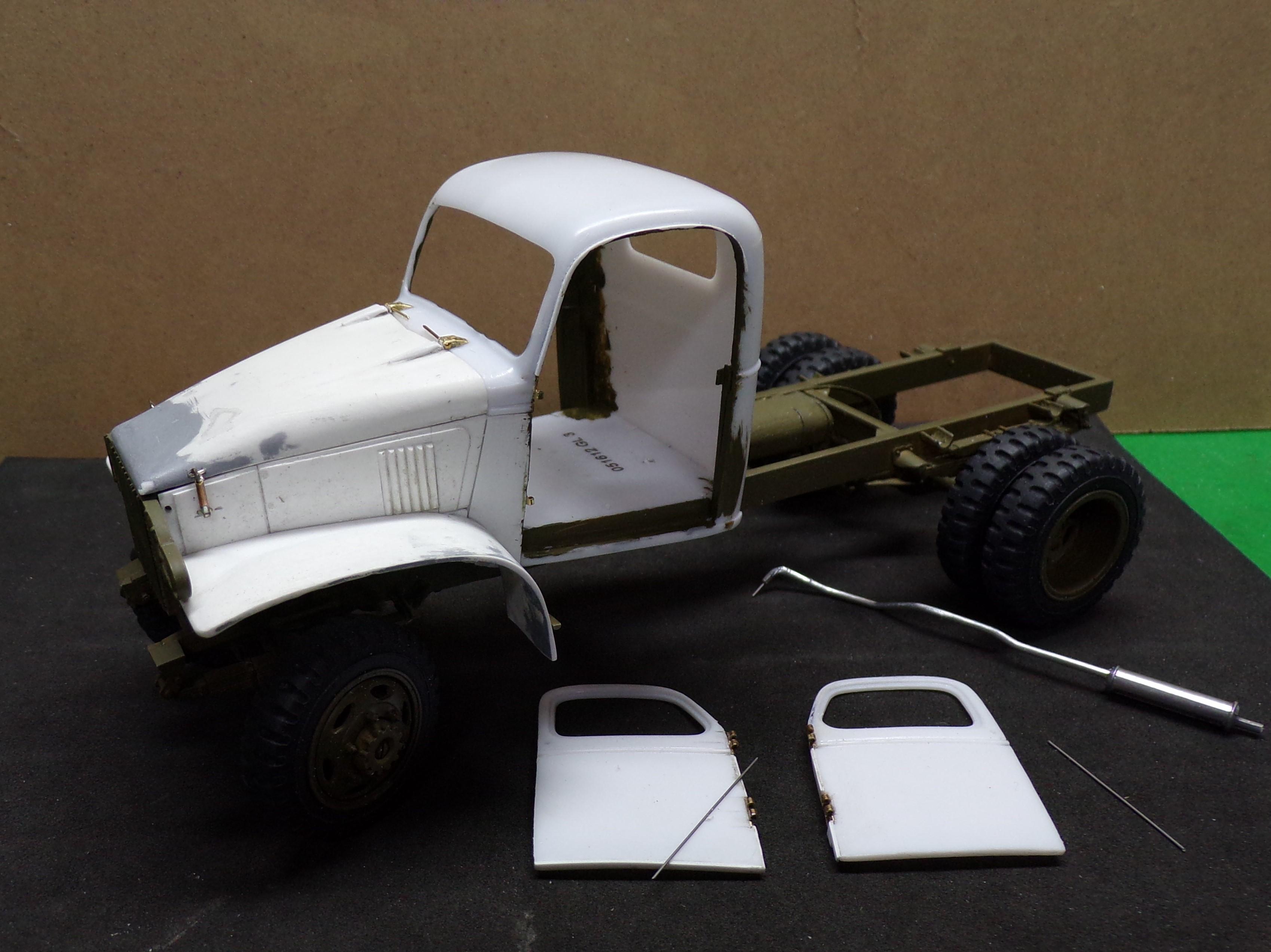
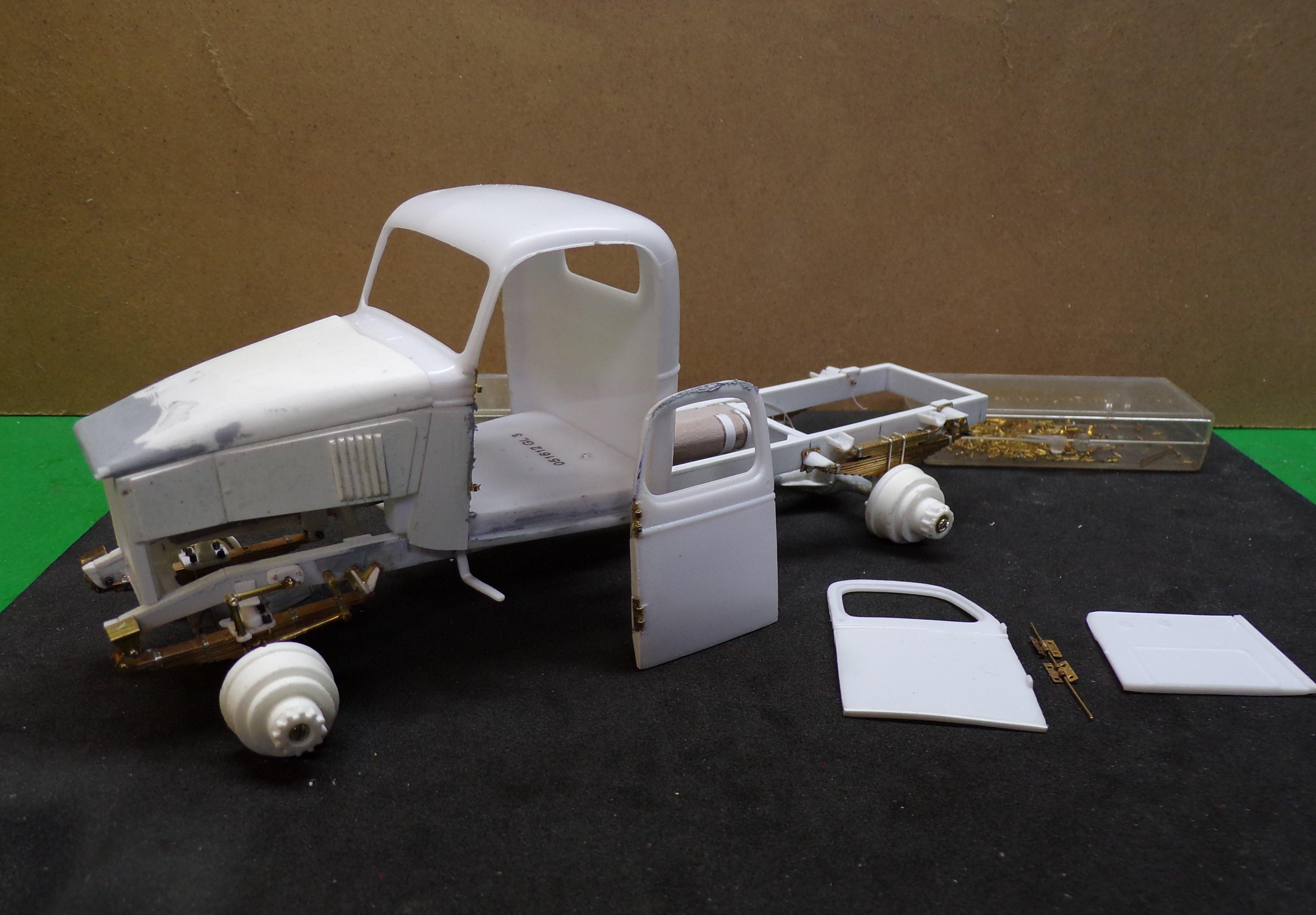
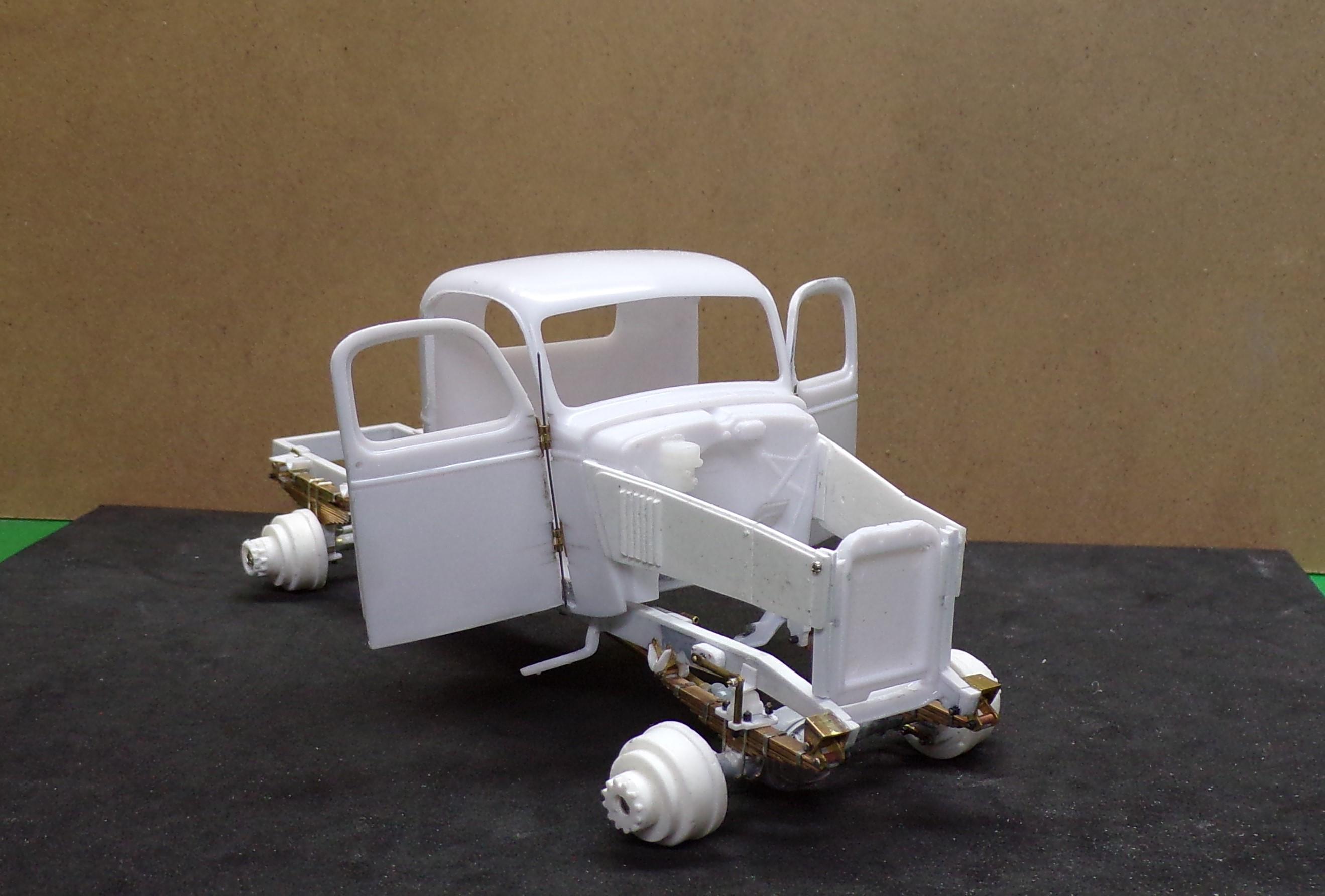
Got a little more done on the cab. Doors were cut free by scribing and then hinged to open. A small rare earth magnet was set in the edge of the door and a piece of wire in the edge of the cab which will hold the door closed. The engine was basically finished up and can be installed once the paint on the frame is done. The hinges were glued with CA into notches cut in the edge of each door with a similar notch cut in the edge of the cab. Then holes were drilled in the doors and cab for small nails to add strength to the hinges. The heads of the nails were ground nearly flat so that the doors will close without binding. A new drip edge at the top of each door will be done to replace the ones that were partially removed during the scribing process.
-
A little CA between the hex bead and the wire hold all in place pretty well. In other places that need to move I pinch the end of the wire with some flat pliers so that it can't pull out of the hole.
-
Only one. I can't think beyond that! 😆
-
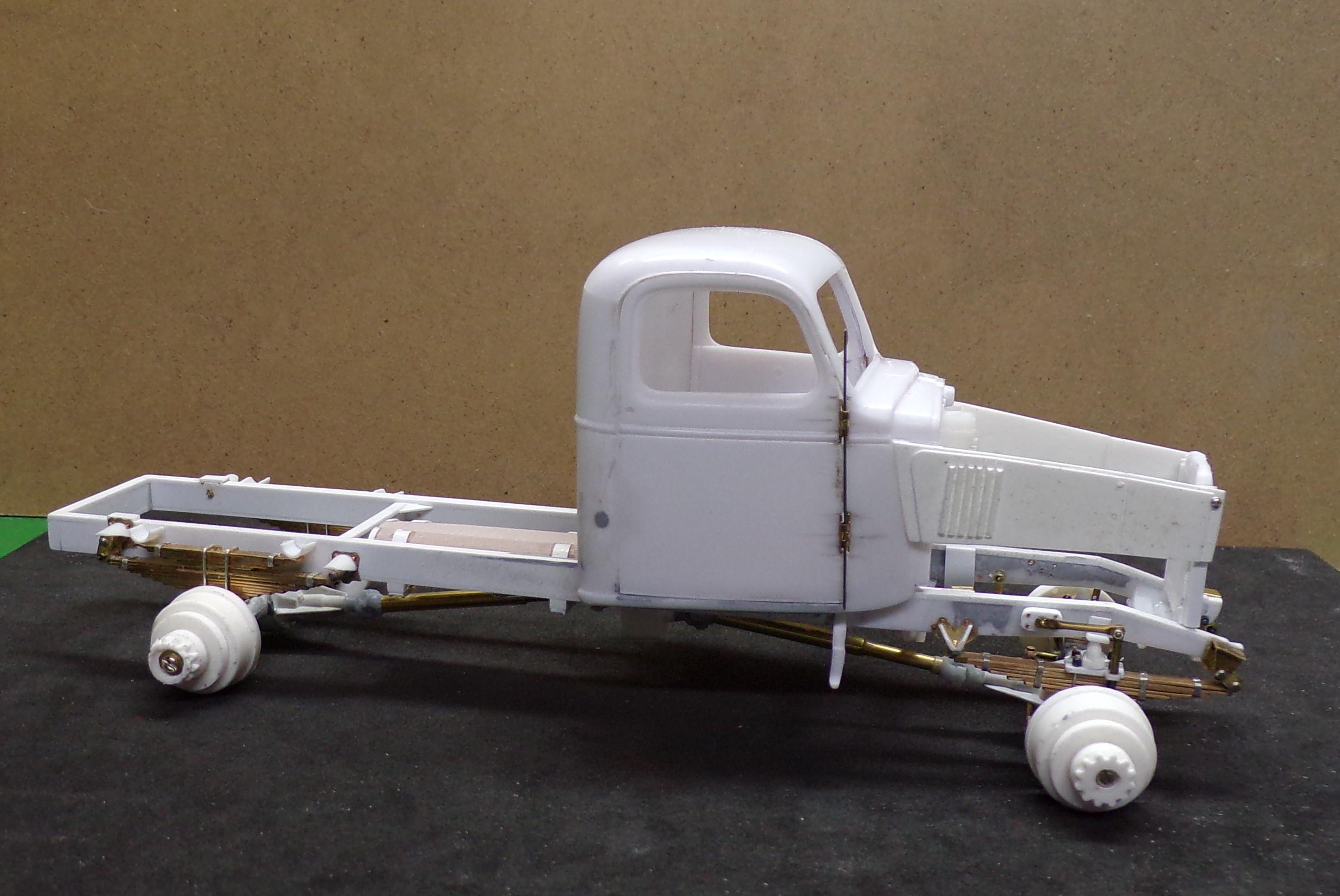
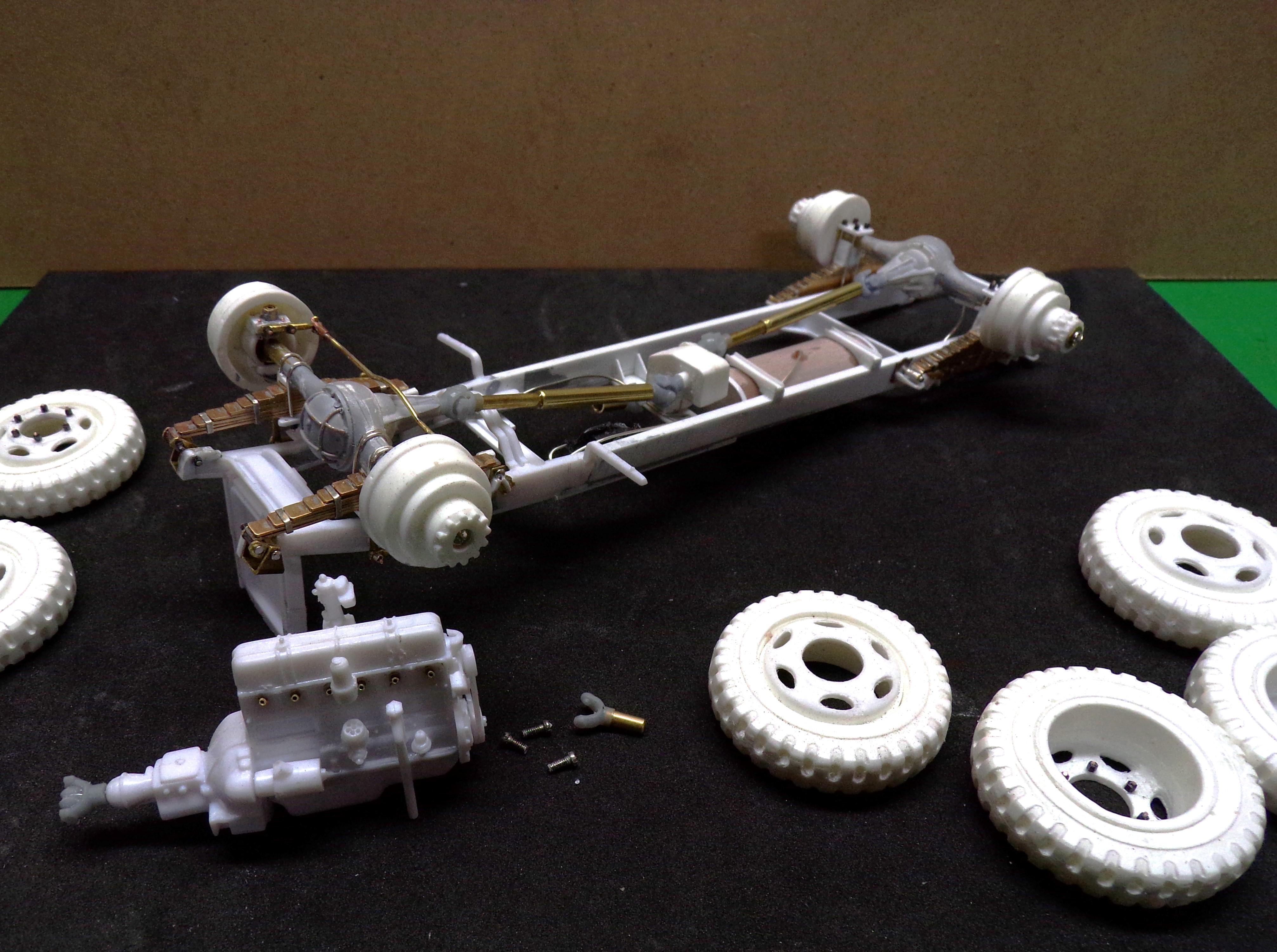
Got a bit more done. Engine detail has been started. The plugs were drilled out and brass tubing was inserted. These will be painted white for the ceramic of the plugs. The distributor was also drilled out for the wiring. Additional details were added to the frame including brake lines, fuel tank, front shocks, and steering arm and pitman. The cab has been set on the frame and is held in place with small screws that project from the frame cross members into the floorboard. With that set the fender locations can be determined. The cab can come off for painting and I still have to open the doors.