Chariots of Fire
-
Posts
2,777 -
Joined
-
Last visited
Content Type
Profiles
Forums
Events
Gallery
Everything posted by Chariots of Fire
-

Build of IH Pumper
Chariots of Fire replied to Chariots of Fire's topic in WIP: Model Trucks: Big Rigs and Heavy Equipment
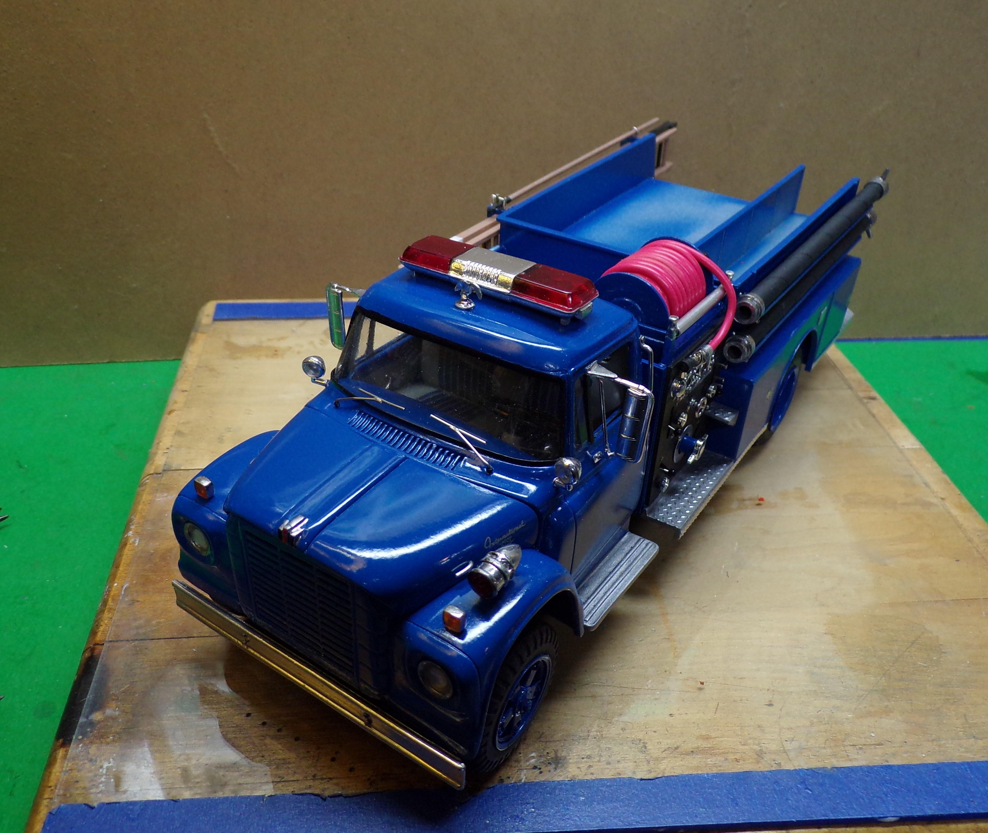
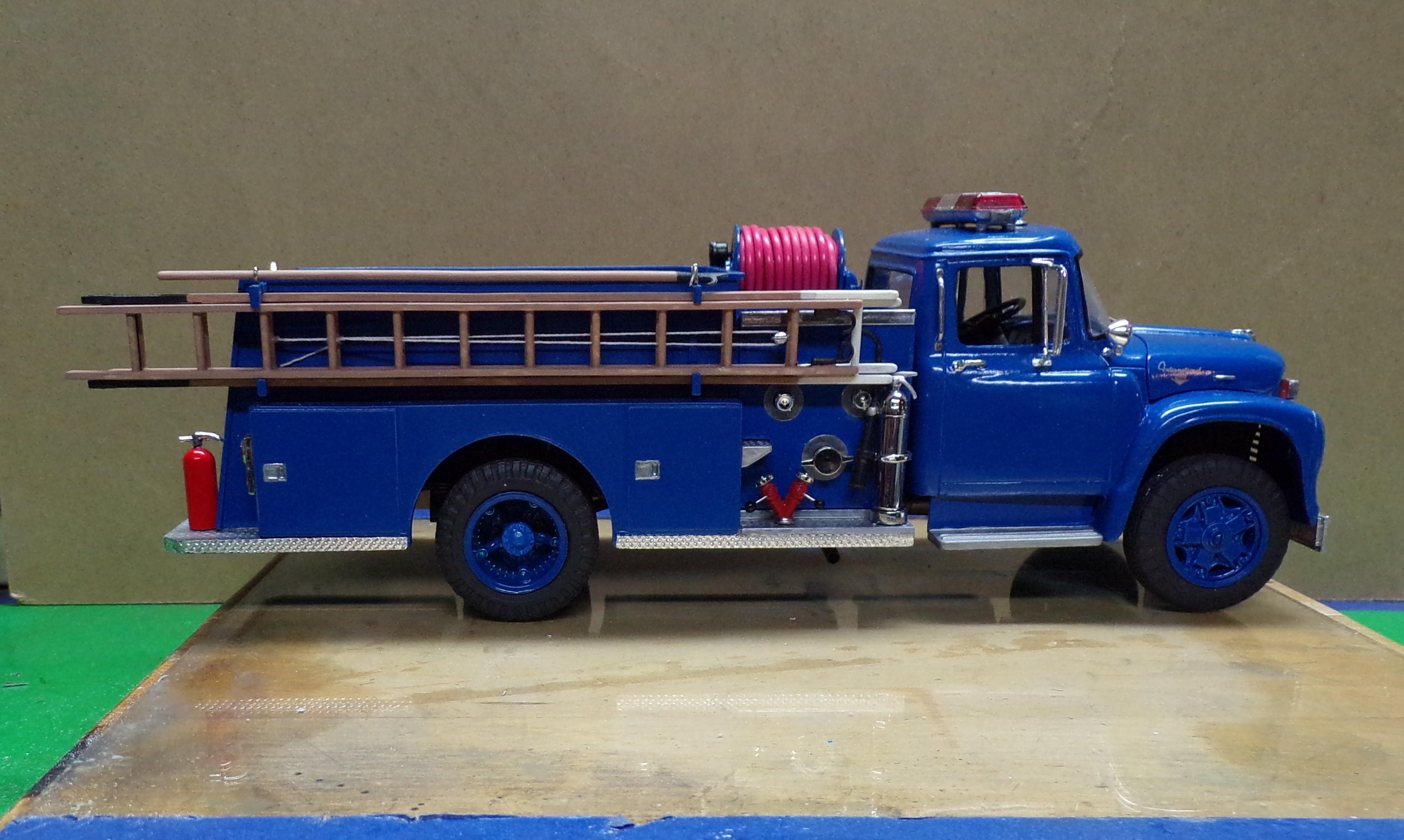
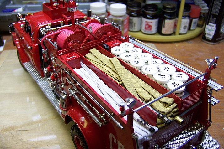
The detailing of pieces to be mounted on the body are getting close to being done. Today I worked on the hose loads. Engines of the day of this rig normally carried two or three different sizes of hose. Working lines of 1-1/2" and 2-1/2" and supply lines of 3". The bed is divided into sections for each size. On the left will be the 1-1/2" working line with additional hose of the same size below it. There is a board separating the two layers that was made up once the first layer was in place. The hose used then was rubber lined with a double cotton jacket on the outside. Today most hose is synthetic. The photo shows the material to be used for the hose along with a piece of plastic that will be painted gray. The hose is sewing elastic and comes in two basic sizes; 1/8" and 1/4". It's about as close as you can get in material that not only looks like hose but is of a reasonable size. It comes in packages of about 3 yards so there is quite a bit to work with. It's white and has to be stained. I found that a good color is Tamiya XF-60 Dark Yellow. Wetting the brush and dipping it into the paint is sufficient to coat the elastic. I generally use a piece of aluminum foil taped to the work area so that things don't get messy. Once that is done several pieces are snipped into short lengths and glued in half like the ones in the photo. More on this a bit later. Got to go and take the dogs out!😆
-
Western Star 4900 FA plow truck
Chariots of Fire replied to BK9300's topic in WIP: Model Trucks: Big Rigs and Heavy Equipment
Such beautiful work! It's going to be too bad to get it all dirty and salty its first day out!😆 -
Build of IH Pumper
Chariots of Fire replied to Chariots of Fire's topic in WIP: Model Trucks: Big Rigs and Heavy Equipment
Just regular old foil, Warren. The thicker kind would be much harder to emboss. And to answer the question about folding it sharply at corners that is further up on the post, it can be done but the difficult part would be to make sure the fold goes exactly with the pattern otherwise it will not look good. On the other hand it does go over rounded corners quite well. Here's the results of doing that on the M-20 prime mover I did a while back. There is no distortion of the pattern either. Note also that foil was used on the face of the running board. The top is regular plastic treadplate. In the photo above it was used to cover the fuel tank. Again, a rounded edge. The foil was laid on first at the outside edge and rolled over the top. In this way I did not have to worry about cutting the edge and getting glue everywhere. Once the glue begins to set at the outside more glue can be added as you move toward the back. Lot less messy that way. It does necessitate being careful not to fold the foil or crush the imprint during this process. After the glue dries it is perfectly hard and not susceptible to damage.
-
Build of IH Pumper
Chariots of Fire replied to Chariots of Fire's topic in WIP: Model Trucks: Big Rigs and Heavy Equipment
Well, yer both right! 😁 -
Build of IH Pumper
Chariots of Fire replied to Chariots of Fire's topic in WIP: Model Trucks: Big Rigs and Heavy Equipment
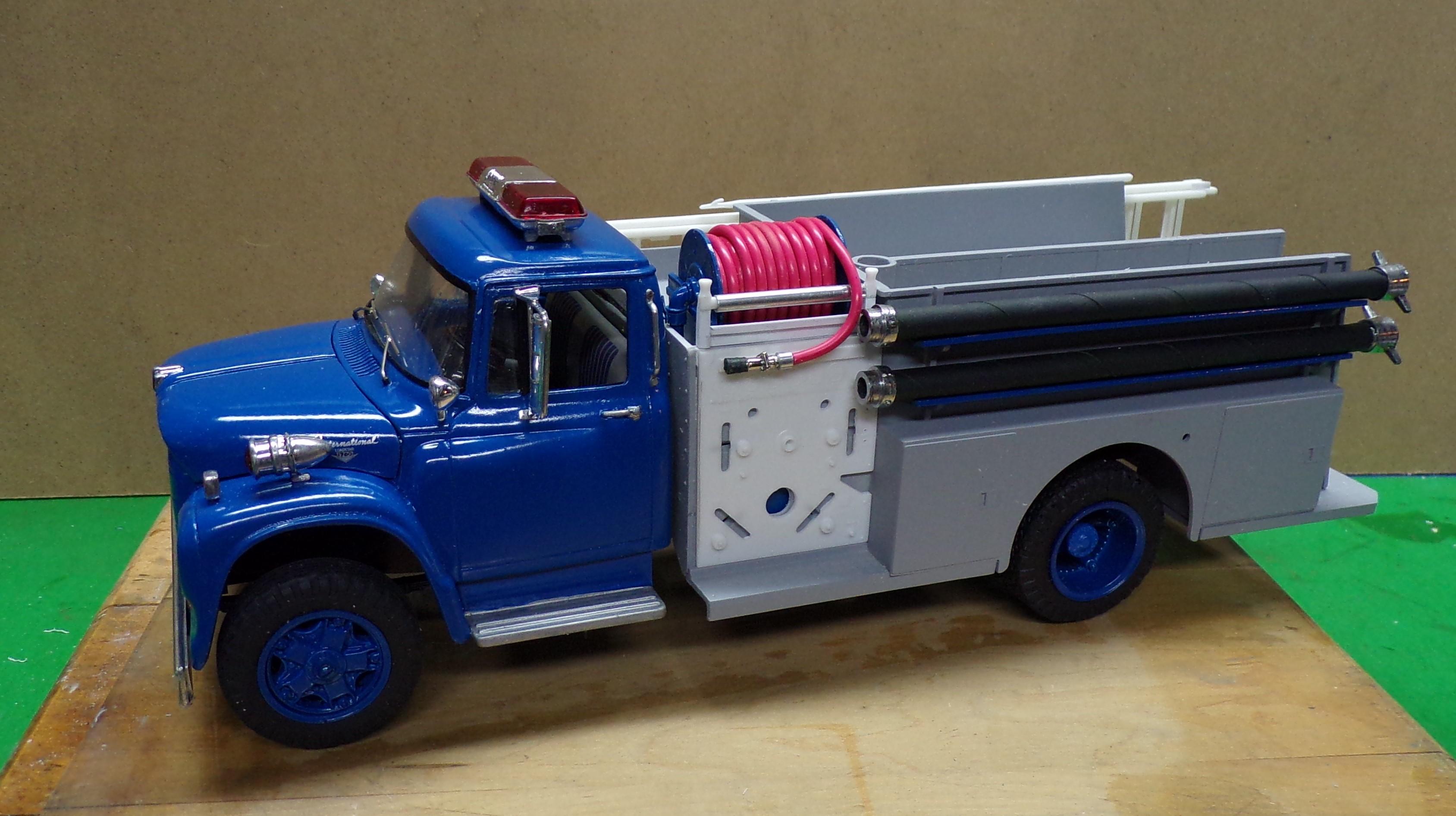
Getting nearer the end of the build. The last thing to do will be the hose load. Still a few details left to go. But here it is as of tonite. This rig is going to be Eagle Hose No. 3. Wonder why!!?! 😎
-
Build of IH Pumper
Chariots of Fire replied to Chariots of Fire's topic in WIP: Model Trucks: Big Rigs and Heavy Equipment
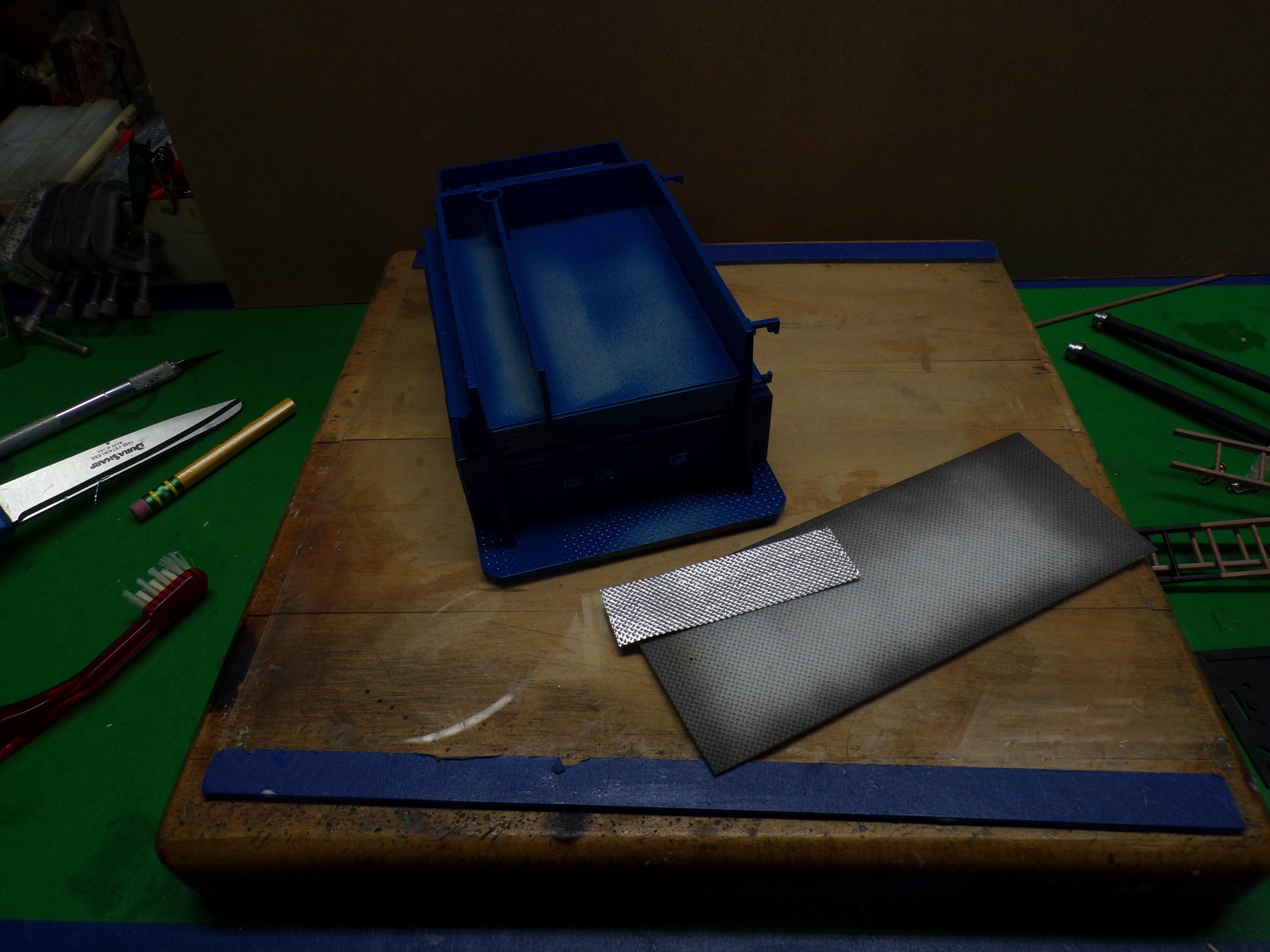
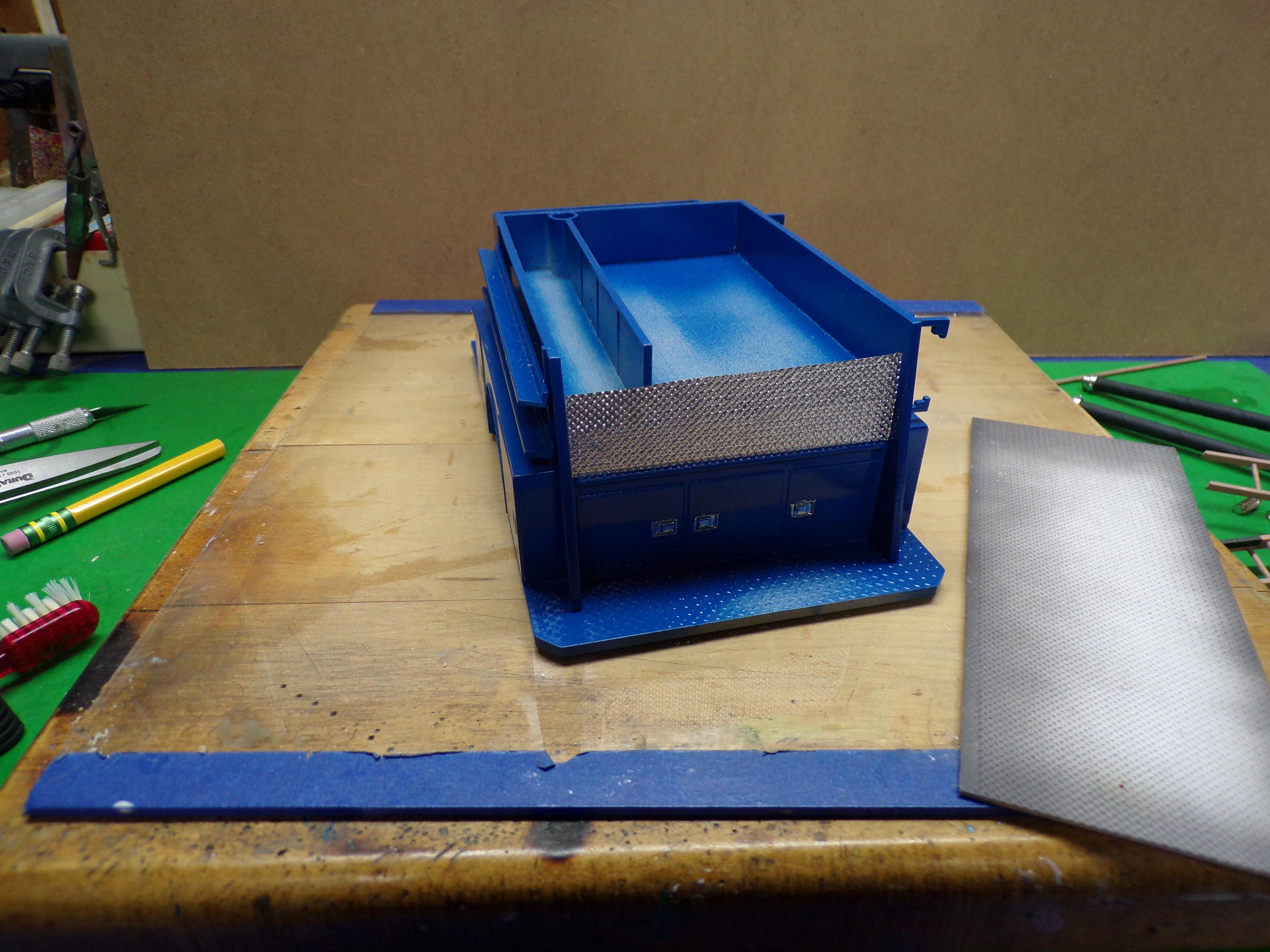
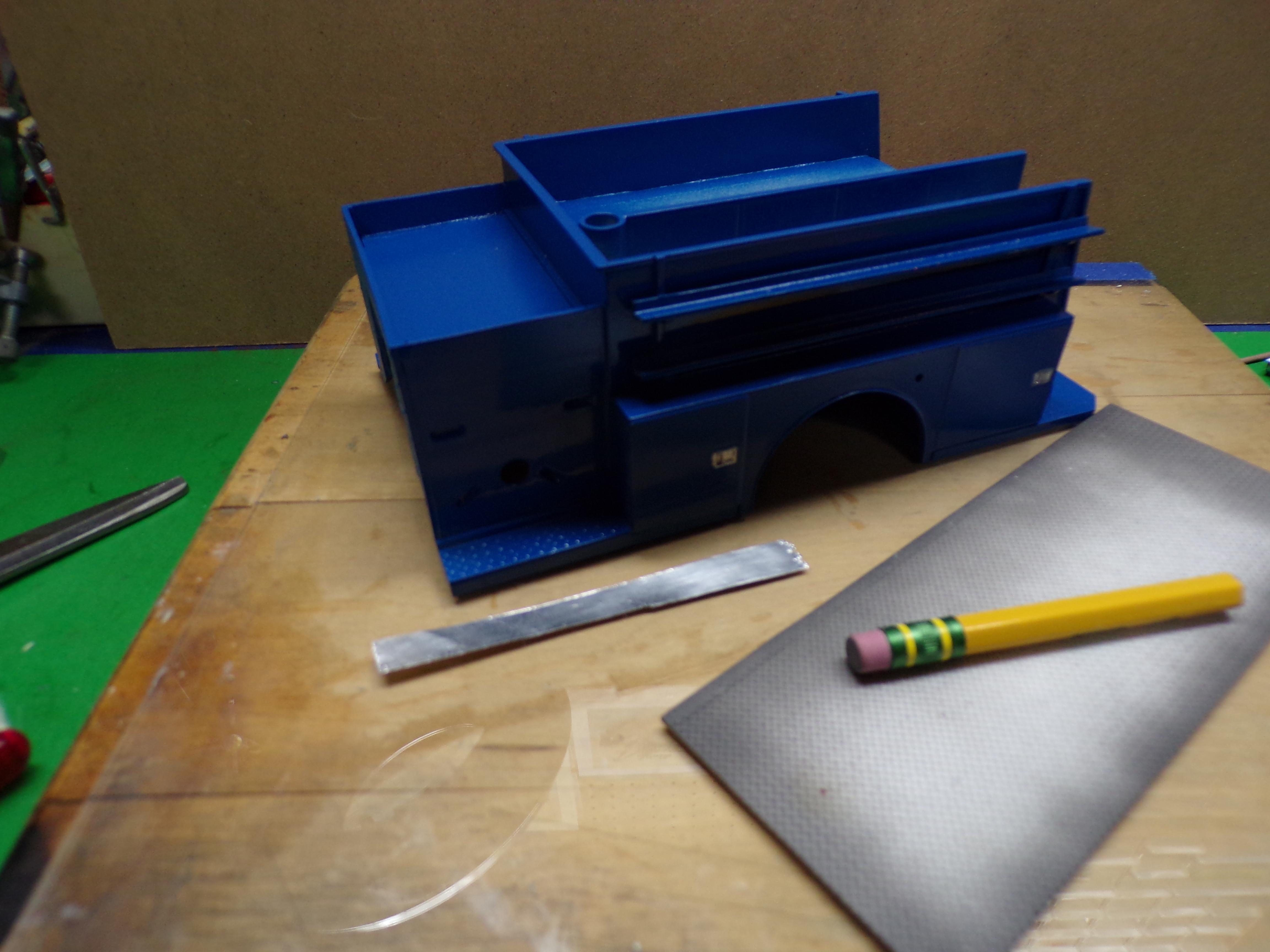
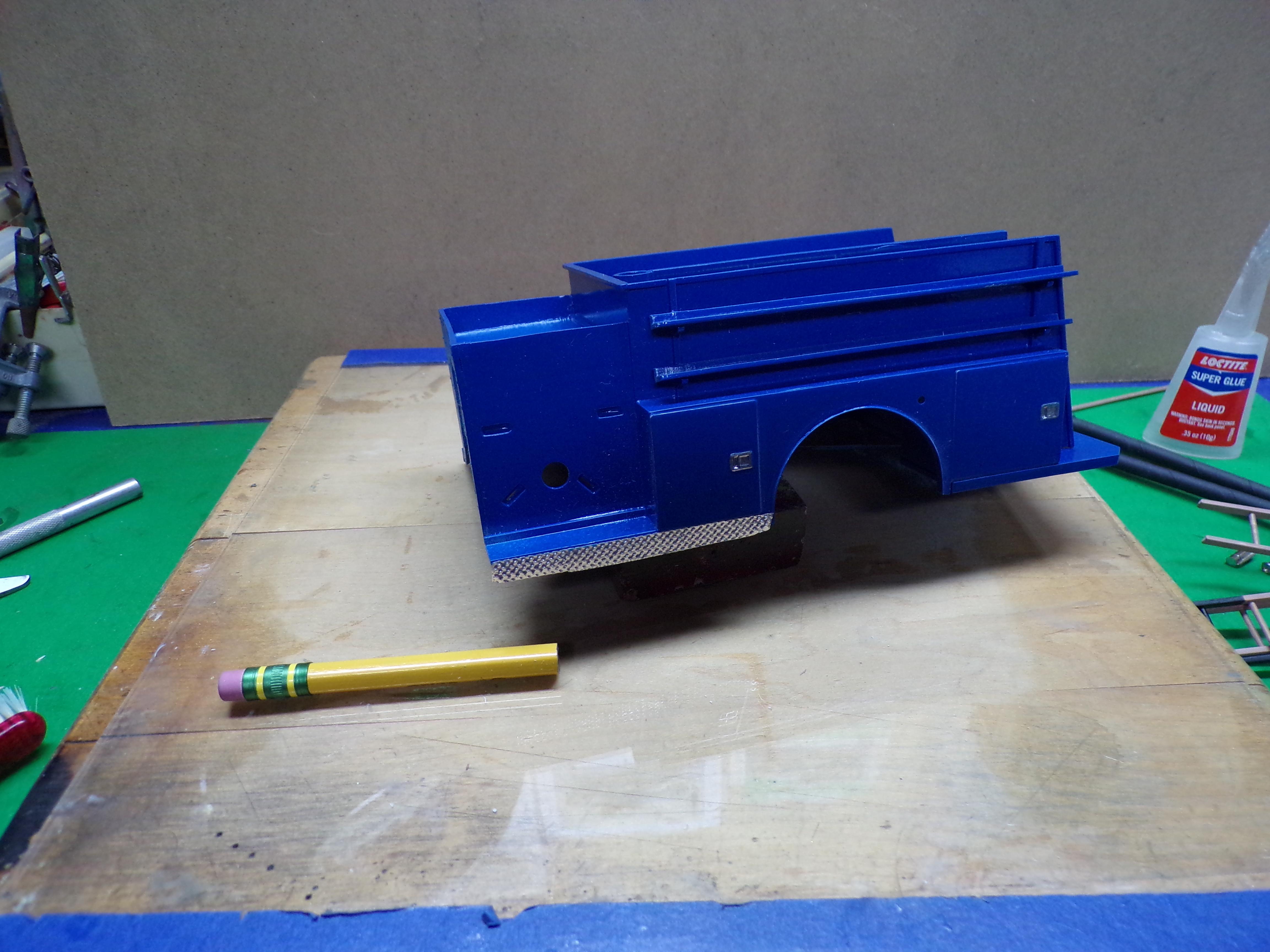
When I first started this post I promised to include how to use aluminum foil for treadplate in certain areas. The following will show some of where the foil has been used and a bit about how it is done. This is a little dark, I know but at least I can give you an explanation. The piece of foil has been cut to width for the area just below the hose bed. It is lying on top of a piece of plastic treadplate. To the left is a pencil with an eraser which was used to press onto the surface of the foil to get the impression of the treadplate underneath. The foil needs to be aligned with the pattern on the treadplate so that it will look right when it is mounted. It takes a while to do the impressions but it is easy to do. Make sure the foil does not slip once you begin the embossing or it will spoil the pattern. The foil has been put in place using CA as a glue. The embossed foil is now place with CA glue. A word about the foil. Use a new Xacto blade to score the foil against a straight edge. Glide the blade over the foil lightly but not with the immediate point. Lay the blade down a bit and let is score the foil a little at a time. Once it is free, you will have a nice straight line which will be the bottom edge in this case. Once the glue has set use the Xacto blade again to cut the foil. Punch through the foil against the edge and at the center. Do not start at the end. Work toward the ends from the center going each way. Again the cut will be neat if you lay the blade down a bit. Do the cutting away from the foil edge so it does not lift up. The results will be as you see below. I'm also doing the edges of the running board, the bottom behind the rear wheels and the edge of the rear step. I start by cutting a thin strip of foil the same as before. One edge needs to be nice and straight with no tears or uneven places. The foil is again laid down on the treadplate and embossed with the pencil eraser. Here's the strip of foil before it is embossed. The Upper edge is straight and clean. The foil has been glued to the running board edge with overhang on the bottom. Don't try and precut this edge or even the length unless you have an enclosed space like the first foil above. It can be easily trimmed afterwards. Keep the glue away from the top edge and don't let it ooze out. Two part epoxy will also work well in attaching the foil. It gives you a lot more working time but you have to be sure that it sets up well before attempting to trim it. I did the rear step and the sides in three pieces. The sides were done first using the same process at with the front running board. But in this case I bent the embossed foil over the beveled corner and then cut the excess off. I did the same to the other side leaving the center of the running board to last. After the foil was trimmed I gave the upper surfaces a coat of Model Master silver. I prefer the dull side of the foil on the outside. I think it looks more in scale and less toy like than if I had used the real shiny side. The silver paint is a close match. The right side of the truck is complete as well. The pump panel is still in need of paint. It will be body color with some chrome trim, intake and discharge caps. I worked on the pump panel in the last couple of days. I chose flat black for the color and highlighted it with several pieces of chrome. The top part of the panel is a section of the pump panel from the 1/32 scale Mack snap kit. The gages are excellent. I cut a hole in the panel and fit the cut section into it and then gave the gages a light black wash. There will be some better photos of it coming up. The Zoet chrome pen worked wonders in several parts of the panel. In the upper left of the panel is a chromed light for night work. I used a clear plastic beady eye for it and removed the bead by cutting a hole in the back. Part of the clear plastic was left uncoated with the upper half chromed. In the meantime I'm going to use the lights from the front of the Mack for the tail lights and directional lights. The directionals are arrow shaped with the tail lights round and above. Tamiya clear orange will be used for the directionals and clear red for the tail lights. The bezels will have to be cut from the grill first and reshaped in the back for mounting. The nice Federal Q siren will be salvaged for the future.
-
Has anybody checked out Doug Whyte's U-tube video on how he blended in body sections without glue! Kind of a neat way to do things.
-
I've tried the stuff that comes in a combined tube for A and B. Never worked out that well because it was difficult to push out equal amounts. I ended up cutting them apart. I note some of you don't like CA and tend to use other adhesives exclusively. Each of us has found through experience what seems to work best. As for me I work almost entirely with CA, using epoxy in those cases where I want some time to adjust or place parts. Clear Gorilla glue works well with headlights, if used sparingly, but it takes a while for it to set up. Lastly, about all small parts get pinned as well as glued in place. It's almost a necessity especially if parts are to be added after painting. Gluing exclusively to painted surfaces almost guarantees that at some point the part will come off.
-
I agree with Pete. Gluing plastic together while it is under stress is asking for trouble. Not only is there a good chance of misalignment but the bond is not going to be as strong. Better to work the parts until they fit or do a tack job with the glue in only those places that meet without clamping and then filling in the gaps with small pieces of plastic. Small gaps can also be closed by putting glue in the joint, wiping off the surface and then sanding the joint before the glue sets. Sanding residue mixes with the glue and forms a good bond.
-
I've successfully used Bob Smith Industries 2-part epoxy for years and have found it to be durable. Mixing is important as Bill has said. The one material that it does not like that well is aluminum. It works but not as well as on other surfaces.
-
One point on the ALPS printer. The colors have to have an opaque background first. So a layer of white is put down first and then the colors go on top. That is probably why the decals sort of disappeared when they were put on. No background. Solid colors like white, black. gold, or silver do not need a background coating first. I use an ALPS all the time and use clear decal film to print them. A good pair of scissors will do the job just fine and you can get really close. It is ok to leave the barest of the clear film around the decal because the clear will disappear once the decal is coated. Testors clear is good for coating but it needs to be applied in either a spray or one stroke of the brush. Any more than that and the decal color will soften and streak leaving a mess.
-
Build of IH Pumper
Chariots of Fire replied to Chariots of Fire's topic in WIP: Model Trucks: Big Rigs and Heavy Equipment
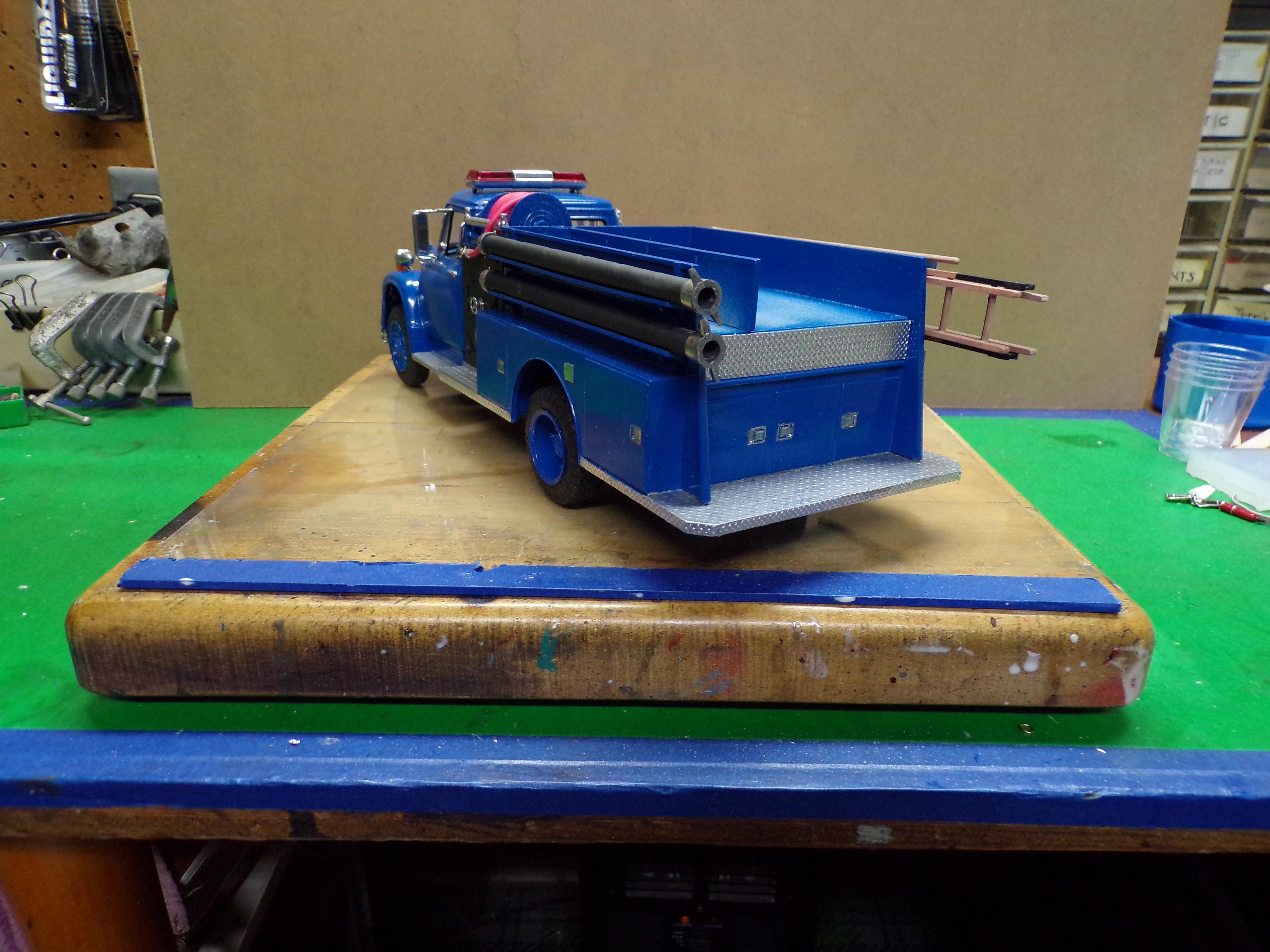
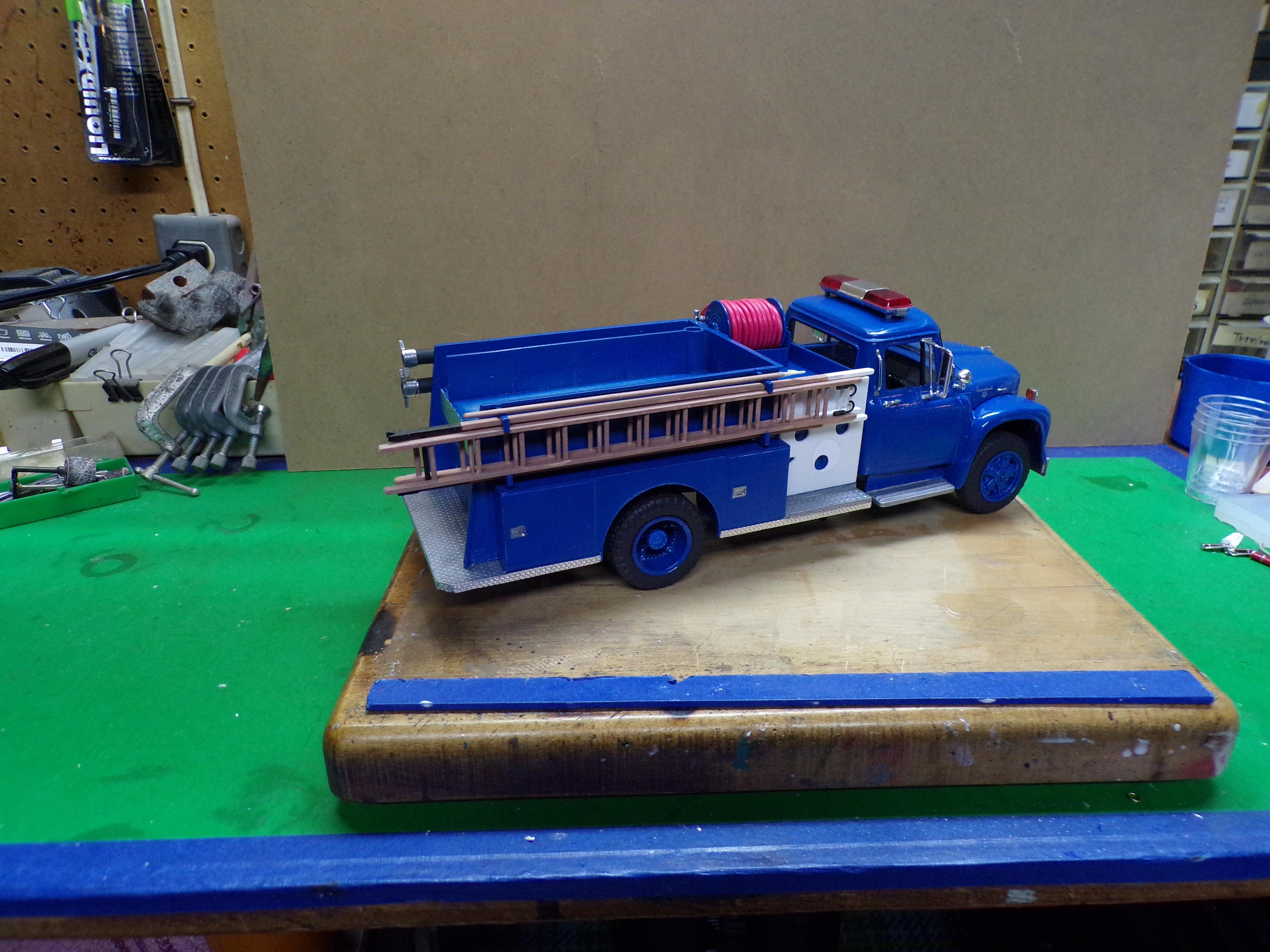
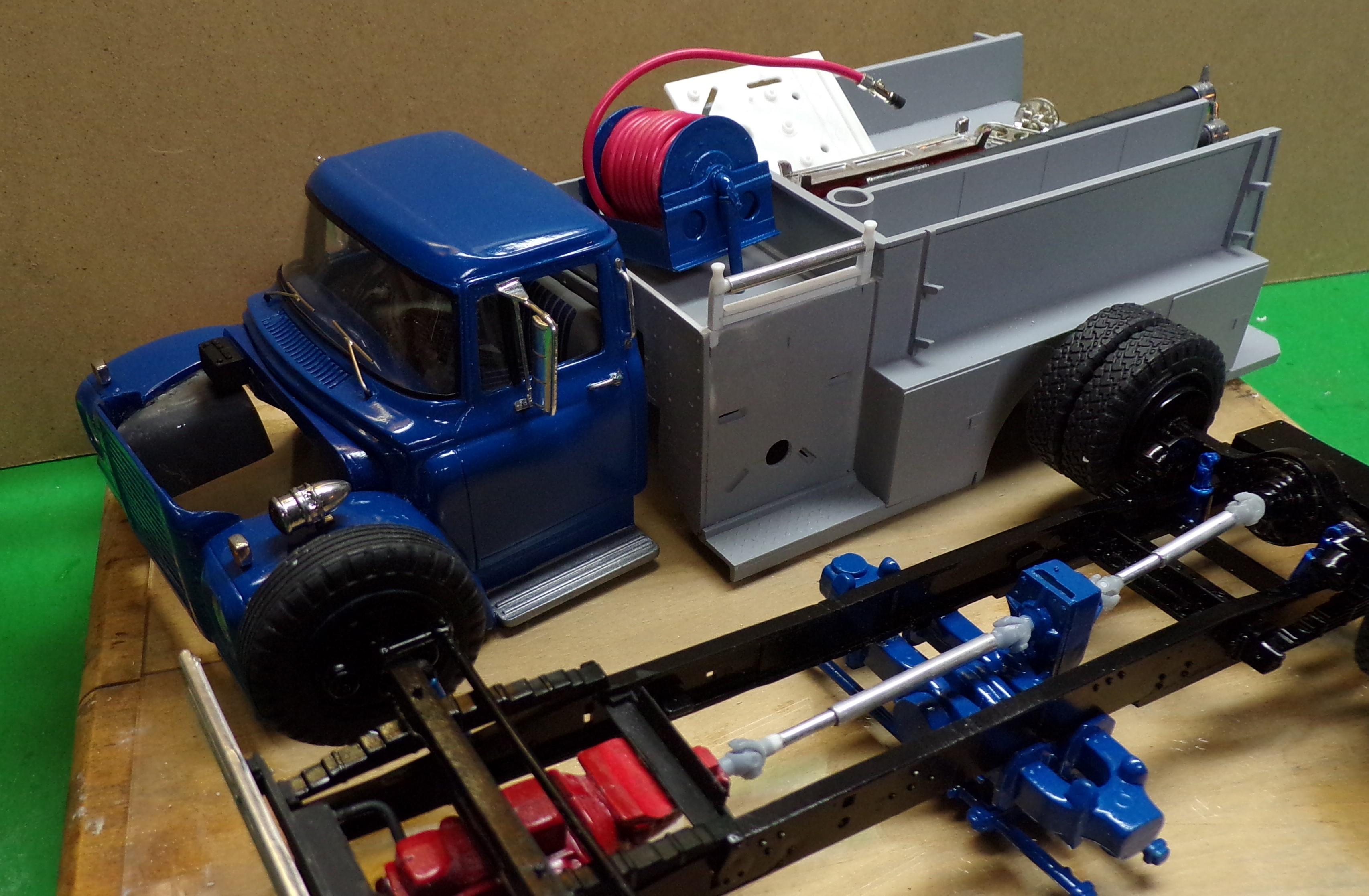
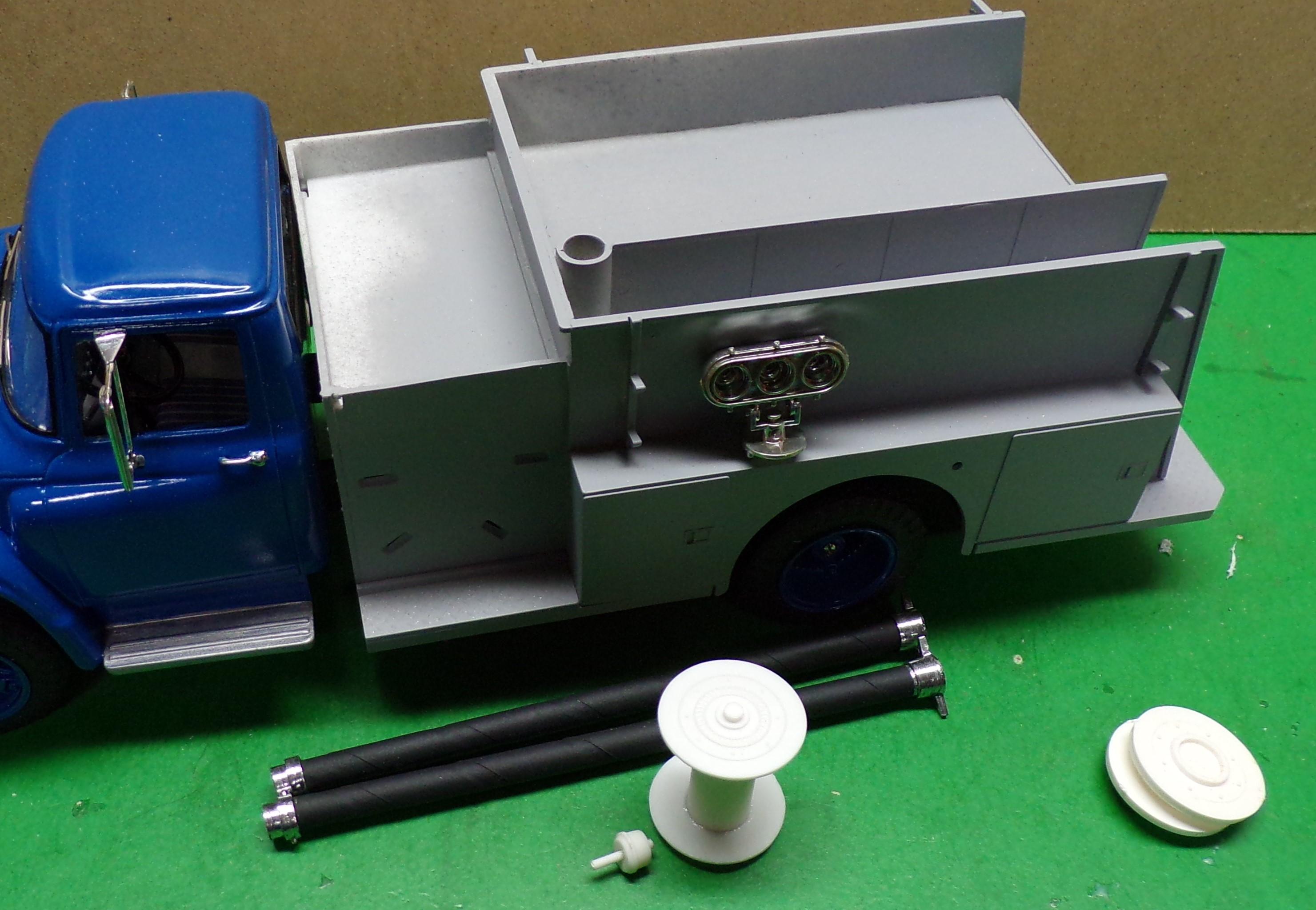
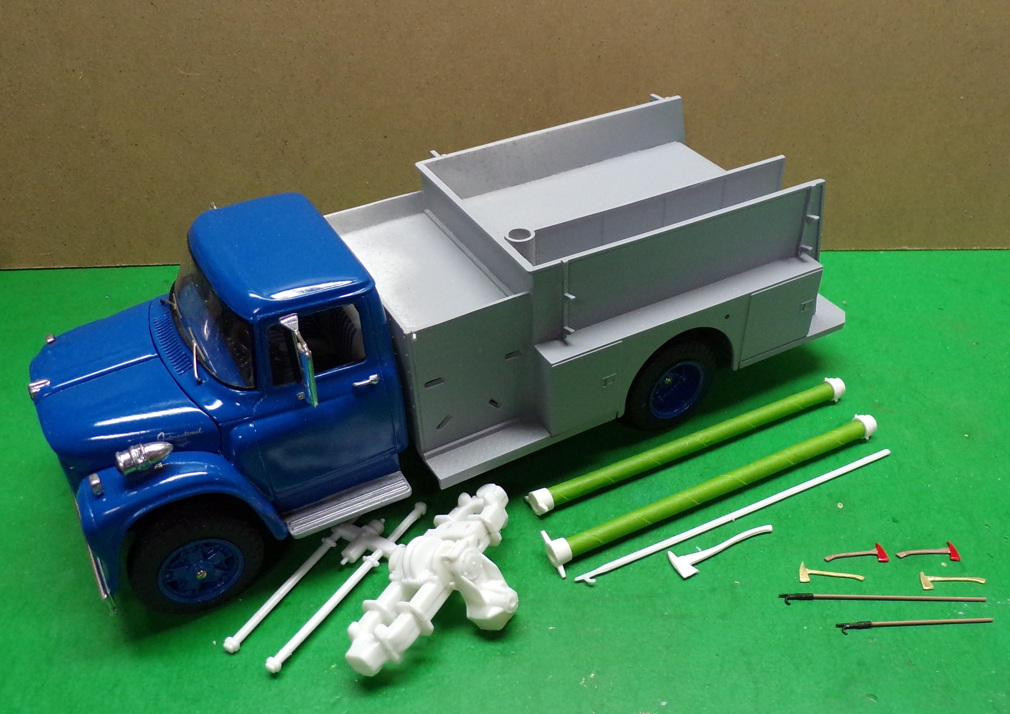
Little things getting done while I wait for the temperature to get a bit warmer. Hood latches added and a light bar is added to the roof. I found this one in the stash and it's a bit smaller than the old one that came from the old Dodge van kit. The hard suction hose trays are painted and are ready to install. Brackets will be made of some strip aluminum and common pins to hold the suction pieces in place. I dug out the ladders from the AMT kit and cleaned them up. Be sure if you use them to scrape away the parting lines from both the outside and inside edges of the rails. I also added some small strips to the base of the main ladder. These pieces are intended to dig in when the ladder is set to keep it from slipping. The roof ladder has two hooks at the top. They are intended to swing out 90 degrees to the plane of the ladder. When it is used, it is slid upside down up a roof and then turned over to allow the hooks to dig into the opposite site of the roof. This keeps the ladder in place and provides a stable place for a firefighter to work. The hose reel is done and ready for mounting once the body is painted. The hose was positioned so that the nozzle will match the location of a simple clip on the face of the pump panel. The guide roller is done but needs to be painted. Fire apparatus of this era would have used either wood or aluminum ground ladders. I will choose wood in this case. Many times equipment was simply transferred from one piece of apparatus to another. And some departments simply like wood ladders. San Francisco, CA is one of those even today and still has its own ladder making facility in house. Wood ladders don't conduct electricity; aluminum ladders do! The ladders represented are a 24' single extension and a 14' roof ladder. The extension ladder will need a halyard and pulley after they are painted. The top of each ladder will be painted white and the base of each will be black.
-
Build of IH Pumper
Chariots of Fire replied to Chariots of Fire's topic in WIP: Model Trucks: Big Rigs and Heavy Equipment
A few things done to the list that will conclude the project. Grab handles were added to the cab. Soft wire was used and bent to form the handles. The ends were drilled through for common pin mounts. The pin heads were ground slightly smaller. The guide roller was added to the top of the body next to the hose reel. The base will be body color. The upright rollers will be chrome painted with a Zoet pen. Drive shafts were made of 3D printed U-joints and some aluminum tubing. The U-joints come in two pieces with one open so that it fits into the center slot of its other half. They can be positioned independently and the shafts slide so that the U-joints are secure. Then a drop of CA is put at the end of the larger tubing to secure the smaller one and keep it from sliding after the U-joints are in position. All will be painted in good time.
-
Build of IH Pumper
Chariots of Fire replied to Chariots of Fire's topic in WIP: Model Trucks: Big Rigs and Heavy Equipment
Here's a Saulsbury rig that was built on a Simon Duplex chassis for the City of Miami, FL. Built for Bob Milnes.
-
Build of IH Pumper
Chariots of Fire replied to Chariots of Fire's topic in WIP: Model Trucks: Big Rigs and Heavy Equipment
Depends on what was necessary to repair it, Brian. If packings needed tightening, they could crawl under the truck to get at it. More sophisticated repairs would mean removing all of the intake and discharge caps, and other small things and then unbolting the entire panel from either the right or the left. They are typically designed to be removable. The officer's side of the truck has a much simpler panel and could be removed much more easily. Also the operator's panel was made in two pieces so that the upper half which contains all of the gages could be left in place. -
Build of IH Pumper
Chariots of Fire replied to Chariots of Fire's topic in WIP: Model Trucks: Big Rigs and Heavy Equipment
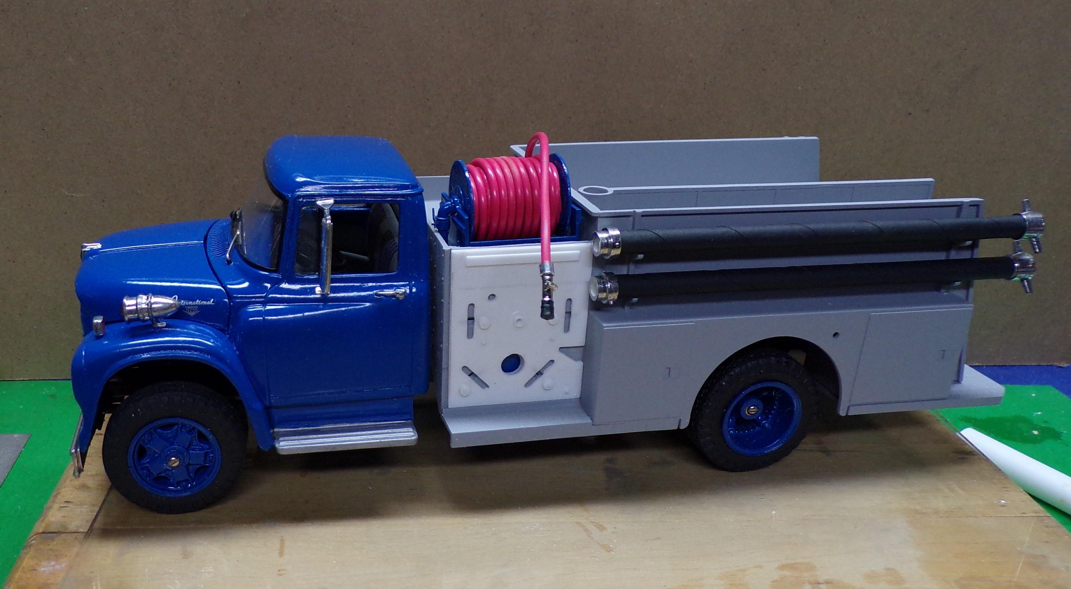
The hose reel has been painted and the frame and supply piping has been added. There is a small valve and lever just before the elbow in the plumbing that will turn the reel off and on for water. The frame work for the hose reel was made from sections of the ALF frame and some strip stock. Pretty much the way a Hannay hose reel would be made. The pump is also painted and mounted on the frame, located so that the suction can be extended through the pump panel sides. I used 18 gage electrical wire for the booster hose. The wire surface was rubbed with steel wool to eliminate the writing on it. At the end is a combination nozzle that was supplied by Don Mills Models. The end was painted flat black. The connection to the "hose" is a piece of aluminum tubing. This is another area where the AMT kit is in error. Black booster hose went out with horses and steamers. Nearly all booster hose is made of a reddish rubber and can be had in either 3/4" or 1" sizes. The size of this hose would be 1". The second error is that they placed the 2-1/2" nozzles on the end of the lines. The kit supplied nozzles are for larger hand lines and are shown with handles. They should not be used on a booster line. After the body is painted and the booster reel is set in place the line will be formed to look like it is draped over the roller guides. The latter have not been made up yet. The "V" shaped opening on the right side of the pump panel is for a step. Note also that the two vertical slots and the two slanted slots are for the handles of the discharge gates. They will be opened up some before the panel is finished and mounted.
-
FDNY Wrecker
Chariots of Fire replied to Scott Eriksen's topic in WIP: Model Trucks: Big Rigs and Heavy Equipment
That's looking nice. I see the decals at the door lines got trimmed ok. New Xacto blade? -
Ford LS Rescue truck
Chariots of Fire replied to gotnitro?'s topic in WIP: Model Trucks: Big Rigs and Heavy Equipment
FWIW take a look at some of the real stuff. Just my opinion but I think the step on the back would look better if it was not real shiny bright. In any event it would not take long to look that way because of foot traffic. Like what you did to the back of the body. The stripes look great. -
Build of IH Pumper
Chariots of Fire replied to Chariots of Fire's topic in WIP: Model Trucks: Big Rigs and Heavy Equipment
The last posts showed the hard suction hose sans paint. Here is the result of painting the hard suctions with Tamiya rubber black (TS-82) and then chroming the couplings with a Zoet pen. The last thing I will do is run my dremel with a small cutter around the inner portions of each coupling to thin them out. Also in the pic is the hose reel made from the two ends supplied in the AMT ALF kit but with one difference. I used my Dremel with a sanding disc to thin them way down. The kit pieces would be about two scale inches in thickness which is all wrong. Thinning them down to less than half that makes the reel look more like it should. The last new addition is the lighting unit . I took one of the better ones from a 1/32 scale Monogram Mack kit to use. Some of these did not get chromed well in the inside but that was taken care of easily with the Zoet pen again. Not sure exactly where this will get mounted, if at all. We'll see! There will be more to come. And in this view there is one more little detail that will make all the difference in how the model will look. One end of the hose reel has a circular gear pattern. The reels were would in two different ways. The first was with a hand crank that operated a bevel gear against the circular gear. The second way was with the use of a small electric motor that has the same bevel gear. An extra brake can will fit the bill for this. Just snip off the long rod and set it against the reel. A small piece of wire would run from the motor to the switch that would be on the pump panel. Below is a look at what a finished one would look like. One missing part of this one, however is the manual crank portion that would be located above the centerline of the reel. Each reel has a motor and a piece of wire run toward the pump panel.
-
Mini Table Saw
Chariots of Fire replied to Chariots of Fire's topic in Model Building Questions and Answers
Well, it does have a variable speed control as well as an electronic board in the corner at the switch. The motor is entirely encased which leads me to believe if there is anything wrong with the motor it might be the brushes (assuming there are some). -
Build of IH Pumper
Chariots of Fire replied to Chariots of Fire's topic in WIP: Model Trucks: Big Rigs and Heavy Equipment
You're right, Bob. The shears would never cut the thicker brass at all. I do use aircraft shears for cutting thin brass and aluminum flashing. -
Any of you use a mini table saw for your modeling work? I bought a Microlux table saw years ago and it has served me well but the other day it decided to stop running. No amount of cleaning has made a difference. Taking it apart is a real chore and I'm not even sure if taking it apart will tell me why it quit. M-M still sells them although they are listed as not in stock and it's not known when they will restock. Besides that, the $$ is nearly 3x what I paid. I'm looking at options seeing as it is one of the more active pieces of machinery I use on my workbench. If you use one or know of one that is good for what we do I'd appreciate your comments.
-
Build of IH Pumper
Chariots of Fire replied to Chariots of Fire's topic in WIP: Model Trucks: Big Rigs and Heavy Equipment
Making a bit more progress, the front bumper has been given a coating of BMF and is mounted. I used the same common pins as bolts as I used in making the windshield wipers. Just the heads and about 1/4" in length. Here are some other things that are in process. The body has been primed for painting and work has begun on the Hale pump. This came from the AMT ALF kit. Hale and Waterous provided most of the in-line pumps for fire apparatus over the years and still do. The AMT pump represents 1000 GPM piece as noted by the four discharge points on the top of the pump. For smaller capacities lots of times all the manufacturer did was cap the discharge and not provide an outlet at the pump panel or on the opposite side of the truck. Each discharge point is equivalent to 250 GPM so using 3 discharges would amount to a 750 pumper. Also in the photo are the two hard suction tubes that will be mounted on the left side of the body. Note!! The AMT and Ertl box art for the ALF has the male and female couplings glued on backwards. My good friend Greg knows all about this and once in a while we will get a laugh about it. Also I have wrapped the tubes in masking tape. Why? Hard suctions of the era, and before, that I am modeling used hard suction tubes of rubber and were also wrapped in metal bands for strength and to keep them from collapse. A hard suction tube is not supposed to collapse seeing as they are most generally used in drafting situations. A collapsed suction hose means no water gets to the pump. So simulating the wrap with tape will give them the look of banded hose when the tubes are painted. The ends will be coated with chrome. The tape also rends the final result with a rough finish look which is what the real stuff would have. The hard suction hose trays need to be added to the body but only after the body is painted. Here's another look but with some other things in view. A friend of mine builds 1/50 scale apparatus and asked me to come up with some pike poles and axes in that scale. As you can see they are half the size of the 1/25 pike pole and axe shown above them. I made printouts of the axe profile and taped them to a piece of 3/64 brass strip and cut them free using a Dremel with a cutting wheel. Two of them were painted. The other two were used for a mold so more can be cast. The pike poles are made from the same old common pins, a piece of small brass tube and a length of plastic rod. (Hope he likes them!)
-
ALF Industrial Pumper
Chariots of Fire replied to Firebuilder's topic in WIP: Model Trucks: Big Rigs and Heavy Equipment
That is BIG water for sure! They will need industrial size mains and in line pumpers to supply those behemoths!😵 -
ALF Industrial Pumper
Chariots of Fire replied to Firebuilder's topic in WIP: Model Trucks: Big Rigs and Heavy Equipment
I was going to ask about the double pump panels. Just MHO but I think the single one looks better and is more prototypical. Nice job putting the two bodies together to form the tandem axle version. Most difficult part of that is hiding the joint between the two pieces!